

2012 Ford Escape Hybrid Workshop Repair Service Manual BEST
What's Included?
Fast Download Speeds
Online & Offline Access
Access PDF Contents & Bookmarks
Full Search Facility
Print one or all pages of your manual

•
NOTE
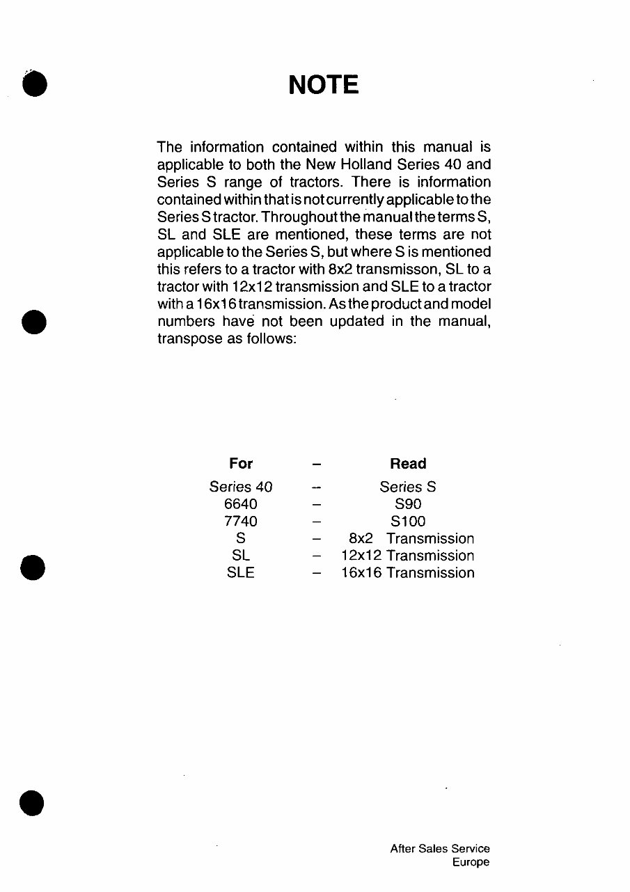
The information contained within this manual is
applicable to both the New Holland Series 40 and
Series S range of tractors. There is information
contained within that is not currently applicable to the
Series S tractor. Throughout the manual the terms S,
SL and SLE are mentioned, these terms are not
applicable to the Series S, but where S is mentioned
this refers to a tractor with 8x2 transmisson, SL to a
tractor with 12x12 transmission and SLE to a tractor
with a 16x16 transmission. As the product and model
numbers have not been updated in the manual,
transpose as follows:
For
Series 40
6640
7740
S
SL
SLE
Read
Series S
S90
S100
8x2 Transmission
12x12 Transmission
16x16 Transmission
After Sales Service
Europe
)
••
•
•
•
I\EW HOLLAI\D
~I
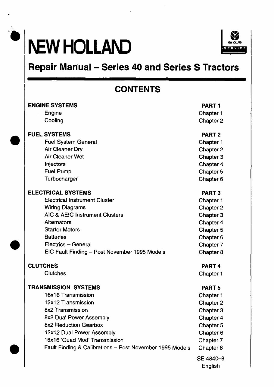
Repair Manual- Series 40 and Series STractors
ENGINE SYSTEMS
Engine
Cooling
FUEL SYSTEMS
Fuel System General
Air Cleaner Dry
Air Cleaner Wet
Injectors
Fuel Pump
Turbocharger
ELECTRICAL SYSTEMS
Electrical Instrument Cluster
Wiring Diagrams
CONTENTS
AIC & AEIC Instrument Clusters
Alternators
Starter Motors
Batteries
Electrics - General
EIC Fault Finding - Post November 1995 Models
CLUTCHES
Clutches
TRANSMISSION SYSTEMS
16x16 Transmission
12x12 Transmission
8x2 Transmission
8x2 Dual Power Assembly
8x2 Reduction Gearbox
12x12 Dual Power Assembly
16x16 'Quad Mod' Transmission
Fault Finding & Calibrations - Post November 1995 Models
PART 1
Chapter 1
Chapter 2
PART 2
Chapter 1
Chapter 2
Chapter 3
Chapter 4
Chapter 5
Chapter 6
PART 3
Chapter 1
Chapter 2
Chapter 3
Chapter 4
Chapter 5
Chapter 6
Chapter?
Chapter 8
PART 4
Chapter 1
PARTS
Chapter 1
Chapter 2
Chapter 3
Chapter 4
Chapter 5
Chapter 6
Chapter?
Chapter 8
SE 4840-8
English
"
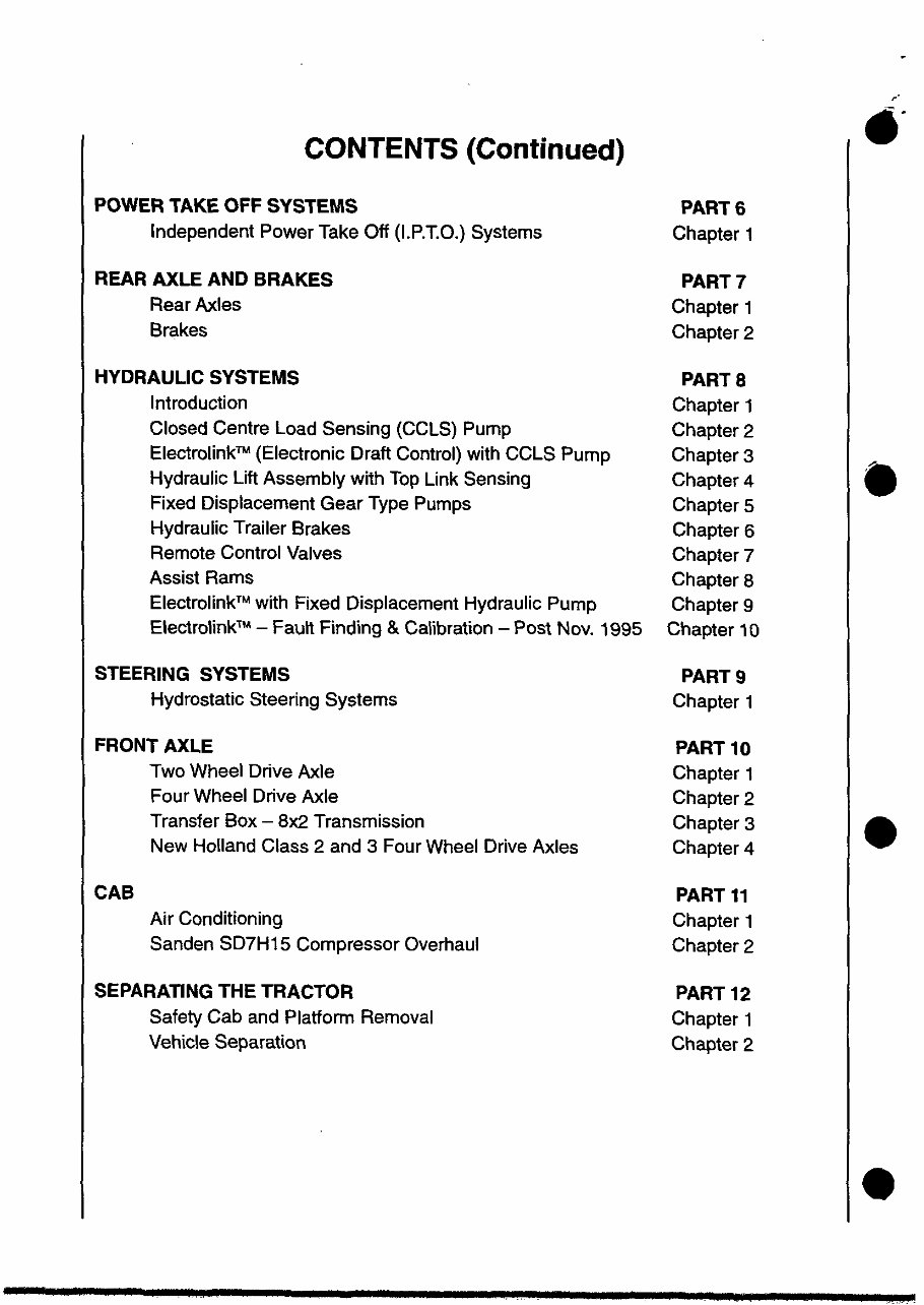
CONTENTS (Continued)
~.
POWER TAKE OFF SYSTEMS
PART 6
Independent Power Take Off (LP.T.O.) Systems
Chapter 1
REAR AXLE AND BRAKES
PART 7
Rear Axles
Chapter 1
Brakes
Chapter 2
HYDRAULIC SYSTEMS
PARTS
Introduction
Chapter 1
Closed Centre load Sensing (CClS) Pump
Chapter 2
Electrolink™ (Electronic Draft Control) with CClS Pump
Chapter 3
•
Hydraulic lift Assembly with Top Link Sensing
Chapter 4
Fixed Displacement Gear Type Pumps
Chapter 5
Hydraulic Trailer Brakes
Chapter 6
Remote Control Valves
Chapter 7
Assist Rams
Chapter 8
Electrolink™ with Fixed Displacement Hydraulic Pump
Chapter 9
Electrolink™ - Fault Finding & Calibration - Post Nov. 1995
Chapter 10
STEERING SYSTEMS
PART 9
Hydrostatic Steering Systems
Chapter 1
FRONT AXLE
PART 10
Two Wheel Drive Axle
Chapter 1
Four Wheel Drive Axle
Chapter 2
Transfer Box - 8x2 Transmission
Chapter 3
•
New Holland Class 2 and 3 Four Wheel Drive Axles
Chapter 4
CAB
PART 11
Air Conditioning
Chapter 1
Sanden SD7H 15 Compressor Overhaul
Chapter 2
SEPARATING THE TRACTOR
PART 12
Safety Cab and Platform Removal
Chapter 1
Vehicle Separation
Chapter 2
•
•
FOREWORD
Appropriate seNice methods and correct repair procedures are essential for the safe, reliable
operation of all equipment as well as the personal safety of the individual performing the repair.
This Repair Manual provides fault finding, overhaul and pressure testing instructions using
recommended procedures and equipment. Following these instructions will ensure the safe,
efficient and timely completion of the seNice or repair. Anyone who departs from these
instructions should be aware that they do so at the risk of compromising their own personal
safety and the safety of others.
Throughout this Manual you will see text in italics, preceded by the words NOTE, IMPORTANT
or WARNING, Such text has the following significance.
NOTE: This text stresses a correct operating procedure or technique.
IMPORTANT: This text stresses a correct operating technique or procedure that, if ignored,
could result in damage to the tractor or equipment.
A WARNING: This text stresses a correct operating technique or procedure that. If
.. ignored, could result in personal injury or death to the Operator or bystanders.
The Manual is divided into Parts, each sub-<:livided in turn into Chapters. Each Chapter
contains information on general operating principles, detailed inspection, overhaul and where
applicable, specific trouble shooting, special tools and specifications. Any reference in this
Manual to right, left, rear, front, top or bottom, is as viewed from the Operator's seat, looking
forward.
All data and illustrations in this Manual are subject to variations in build specification. This
information was correct at the time of issue, but Ford New Holland policy is one of continuous
improvement and the right to change specifications, equipment or design at any time, without
notice, is reseNed.
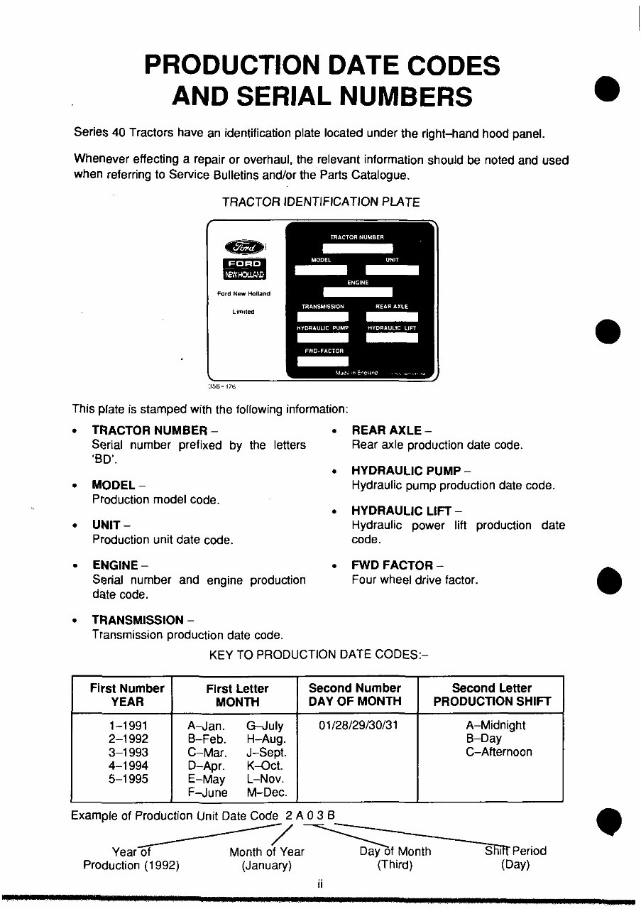
PRODUCTION DATE CODES
AND SERIAL NUMBERS
Series 40 Tractors have an identification plate located under the right-hand hood panel.
Whenever effecting a repair or overhaul, the relevant information should be noted and used
when referring to Service Bulletins and/or the Parts Catalogue.
TRACTOR IDENTIFICATION PLATE
Ford New Holland
358-176
This plate is stamped with the following information:
•
•
•
•
•
TRACTOR NUMBER -
Serial number prefixed by the letters
'BD'.
MODEL-
Production model code.
UNIT-
Production unit date code.
ENGINE-
Serial number and engine production
date code.
TRANSMISSION -
Transmission production date code.
• REAR AXLE-
Rear axle production date code.
• HYDRAULIC PUMP -
Hydraulic pump production date code.
• HYDRAULIC LIFT -
Hydraulic power lift production date
code.
• FWD FACTOR -
Four wheel drive factor.
KEY TO PRODUCTION DATE CODES:-
First Number FI rst Letter Second Number Second Letter
YEAR MONTH DAY OF MONTH PRODUCTION SHIFT
1-1991 A-Jan. G-July 01/28/29/30/31 A-Midnight
2-1992 B-Feb. H-Aug. 8-Day
3-1993 C-Mar. J-Sept. C-Afternoon
4-1994 D-Apr. K--0ct.
5-1995 E-May L-Nov.
F-June M-Dec.
Example of Production Unit Date Code 2 A 0 3 B
~----/ ~----~
Yearof Month of Year Day of Month Shiff Period
Production (1992) (January) (Third) (Day)
ii
•
•
•
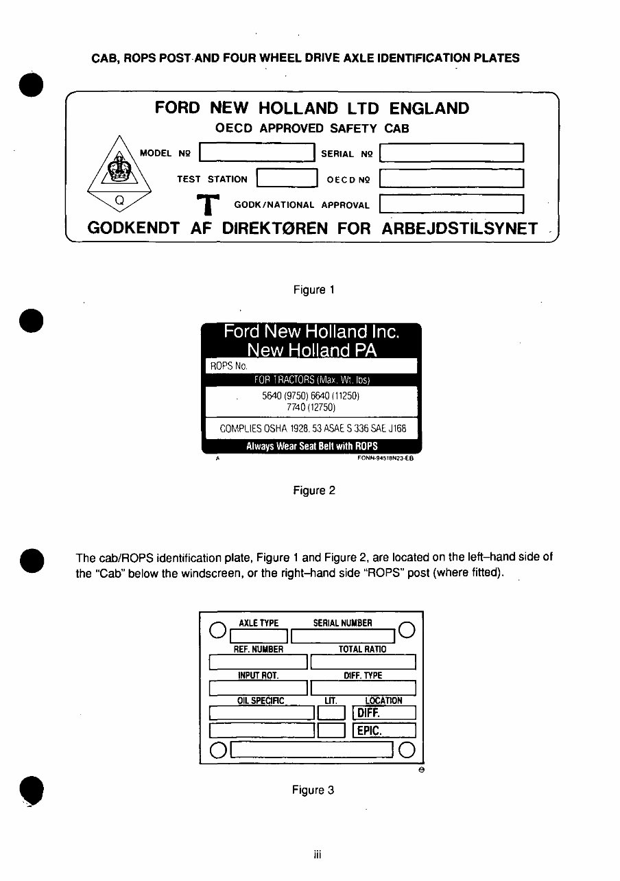
CAB, ROPS POST AND FOUR WHEEL DRIVE AXLE IDENTIFICATION PLATES
Q
FORD NEW HOLLAND LTD ENGLAND
OECD APPROVED SAFETY CAB
! SERIAL NQ I
L-----;:===~ ~=========~
L..-__ -'! 0 E C 0 NQ
T GODK/NATIONAL APPROVAL
GODKENDT AF DIREKT0REN FOR ARBEJDSTILSYNET
,
Figure 1
5640 (9750) 6640 (11250)
7740 (12750)
COMPLIES OSHA 1928.53 ASAE S 336 SAE J168
Always Wear Seal Belt with ROPS
FONN·945T8NZJ·EB
Figure 2
The cab/ROPS identification plate, Figure 1 and Figure 2, are located on the left-hand side 01
the "Cab" below the windscreen, or the right-hand side ''ROPS'' post (where fitted).
O
AXLE TYPE SERIAL NUMBER 0
I II I
REF. NUMBER L------:;T;;;;OT'""AL;-;R;-:;ATI;;;;O~
L-~==~~ILI __ ==== __ ~
INPUT ROT. DIFF. TYPE
~-=~==~I~I~--~==~
OIL SPECIRe LIT. LOCATION
:======:ID ~I D~IF~F. ==:
IDIEPIC.
01 10
Figure 3
iii
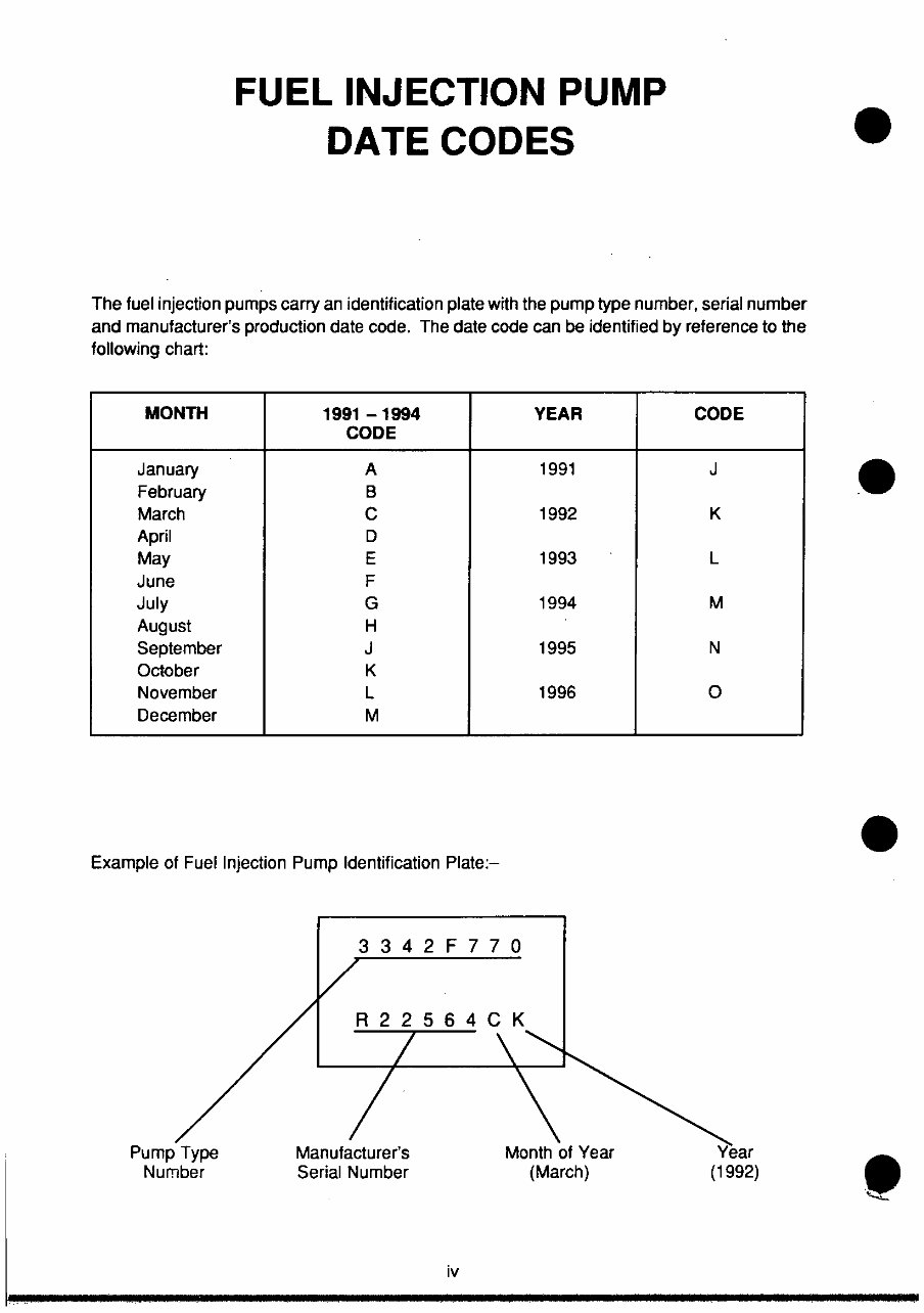
FUEL INJECTION PUMP
DATE CODES
The fuel injection pumps carry an identification plate with the pump type number, serial number
and manufacturer's production date code. The date code can be identified by reference to the
following chart:
MONTH 1991 -1994 YEAR
CODE
January A 1991
February B
March C 1992
April D
May E 1993
June F
July G 1994
August H
September J 1995
October K
November L 1996
December M
Example of Fuel Injection Pump Identification Plate:-
Pump Type
Number
334 2 F 770
R22564CK
Manufacturer's
Serial Number
iv
Month of Year
(March)
CODE
J
K
L
M
N
0
Year
(1992)
•
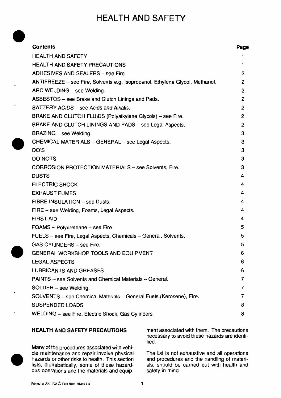
HEALTH AND SAFETY
Contents Page
HEALTH AND SAFETY 1
HEALTH AND SAFETY PRECAUTIONS 1
ADHESIVES AND SEALERS - see Fire 2
ANTIFREEZE - see Fire, Solvents e.g. Isopropanol, Ethylene Glycol, Methanol. 2
ARC WELDING - see Welding. 2
ASBESTOS - see Brake and Clutch Linings and Pads. 2
BATTERY ACIDS - see Acids and Alkalis. 2
BRAKE AND CLUTCH FLUIDS (Polyalkylene Glycols) - see Fire. 2
BRAKE AND CLUTCH LININGS AND PADS -see Legal Aspects.
BRAZING - see Welding.
CHEMICAL MATERIALS - GENERAL - see Legal Aspects.
DO'S
DO NOTS
CORROSION PROTECTION MATERIALS - see Solvents, Fire.
DUSTS
ELECTRIC SHOCK
EXHAUST FUMES
FIBRE INSULATION - see Dusts.
FIRE - see Welding, Foams, Legal Aspects.
FIRST AID
FOAMS - Polyurethane - see Fire.
FUELS - see Fire, Legal Aspects, Chemicals - General, Solvents.
GAS CYLINDERS - see Fire.
GENERAL WORKSHOP TOOLS AND EQUIPMENT
LEGAL ASPECTS
LUBRICANTS AND GREASES
PAINTS - see Solvents and Chemical Materials - General.
SOLDER - see Welding.
SOLVENTS - see Chemical Materials - General Fuels (Kerosene), Fire.
SUSPENDED LOADS
WELDING - see Fire, Electric Shock, Gas Cylinders.
2
3
3
3
3
3
4
4
4
4
4
4
5
5
5
6
6
6
7
7
7
8
8
HEALTH AND SAFETY PRECAUTIONS ment associated with them. The precautions
necessary to avoid these hazards are identi-
fied.
Many of the procedures associated with vehi-
cle maintenance and repair involve physical
hazards Or other risks to health. This section
lists, alphabetically, some of these hazard-
ous operations and the materials and equip-
Prlnled In UK 11\12 © Ford New Holland Ltd
1
The list is not exhaustive and all operations
and procedures and the handling of materi-
als, should be carried out with health and
safety in mind.
You're Reading a Preview
What's Included?
Fast Download Speeds
Online & Offline Access
Access PDF Contents & Bookmarks
Full Search Facility
Print one or all pages of your manual
$36.99
$48.99
Viewed 44 Times Today


Secure transaction
What's Included?
Fast Download Speeds
Online & Offline Access
Access PDF Contents & Bookmarks
Full Search Facility
Print one or all pages of your manual
$36.99
$48.99
This Workshop Repair Service Manual for the 2012 Ford Escape Hybrid is a comprehensive resource for repairing, maintaining, and refurbishing your vehicle. It covers all diagnostic and repair procedures in great detail, making it useful for both professional technicians and DIY enthusiasts.
The manual includes high-quality photos, illustrations, and diagrams, ensuring that all repair procedures are covered from A-Z. It is a valuable resource for anyone looking to work on their 2012 Ford Escape Hybrid.
Service Manual Details:
- Printable: YES
- Requirements: PDF Reader/Web Browser
- File Type: .PDF/.HTML/.JPG
- Compatibility: All Versions of Windows, Mac, and Linux
Table of Content (example):
- GENERAL INFORMATION
- ENGINE
- Engine Mechanical
- Engine Lubrication System
- Engine Cooling System
- Engine Control System
- Fuel System
- Exhaust System
- TRANSMISSION/TRANSAXLE
- Clutch
- Manual Transaxle
- Automatic Transaxle
- DRIVELINE/AXLE
- Front Axle
- Rear Axle
- SUSPENSION
- Front Suspension
- Rear Suspension
- Road Wheels & Tyres
- BRAKES
- Brake System
- Parking Brake System
- Brake Control System
- STEERING
- Power Steering System
- Steering System
- RESTRAINTS
- Seat Belts
- Supplemental Restraint System (SRS)
- BODY
- Body, Lock & Security System
- Glasses, Window System & Mirrors
- Roof
- Exterior & Interior
- Instrumental Panel
- Seat
- AIR CONDITIONER
- Air Conditioner System
- ELECTRICAL
- Wiring Diagrams
- Starting & Charging System
- Lighting System
- Driver Information System
- Wiper, Washer & Horn
- Body Control System
- Lan System
- Audio Visual, Navigation & Telephone System
- Auto Cruise Control System
- Power Supply, Ground & Circuit Elements
- MAINTENANCE
- INDEX
- Alphabetical Index


