
![Ford E-450 2011 Repair Workshop Repair & Service Manual [COMPLETE & INFORMATIVE for DIY Repair] ☆ ☆ ☆ ☆](https://cdm.emanualonline.com/media/catalog/product/cache/518e89fe08903fc357b0d05eb410bb22/3/0/303407-1.jpg "Ford E-450 2011 Repair Workshop Repair & Service Manual [COMPLETE & INFORMATIVE for DIY Repair] ☆ ☆ ☆ ☆")
2011 Ford E-450 Service & Repair Manual
What's Included?
Fast Download Speeds
Offline Viewing
Access Contents & Bookmarks
Full Search Facility
Print one or all pages of your manual

2011 E-Series
Workshop Manual
Quick Links
Introduction
Master DTC Chart
Specifications
Metrics
Torque Wrench Adapter Formulas
Acronyms
Alphabetical Index
Table of Contents
1: General Information
00: Service Information
2: Chassis
04: Suspension
05: Driveline
06: Brake System
11: Steering System
3: Powertrain
03: Engine
07: Automatic Transmission
09: Exhaust System
10: Fuel System
4: Electrical
12: Climate Control System
13: Instrumentation and Warning Systems

14: Battery and Charging System
15: Audio Systems
17: Lighting
18: Electrical Distribution
19: Electronic Feature Group
5: Body and Paint
01: Body
02: Frame and Mounting
SECTION 100-00: Service Information 2011 E-Series Workshop Manual
DESCRIPTION AND OPERATION Procedure revision date: 04/27/2012
Symbols Glossary
Symbols are used inside the graphics and in the text area to enhance the information.
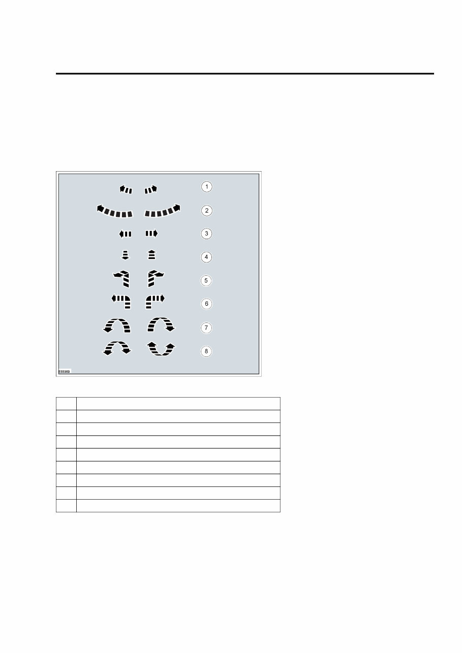
Movement Symbols
Movement symbols provide detailed information to a required component movement. These component
movements can be rotational or 1-3 dimensional movements.
Item Description
1 Minor component movement clockwise/counterclockwise
2 Major component movement clockwise/counterclockwise
3 Component movement to the left/right/up/down
4 Component movement towards/away
5 3 dimensional component movement
6 2 dimensional component movement
7 3 dimensional component rotation
8 3 dimensional component cycling
Turn Symbols
Turn symbols are used to provide further information on the direction or angle of component turns.
2011 E-Series Workshop Manual
Symbols Glossary 1
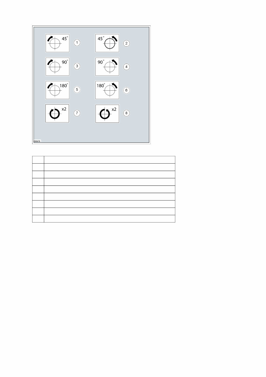
Item Description
1 Turn the component clockwise through 45°
2 Turn the component counterclockwise through 45°
3 Turn the component clockwise through 90°
4 Turn the component counterclockwise through 90°
5 Turn the component clockwise through 180°
6 Turn the component counterclockwise through 180°
7 Turn the component clockwise through 2 complete turns
8 Turn the component counterclockwise through 2 complete turns
Steering Wheel Symbols
Steering wheel symbols are used to provide further information to a required steering wheel position or
steering column lock status.
2011 E-Series Workshop Manual
Symbols Glossary 2
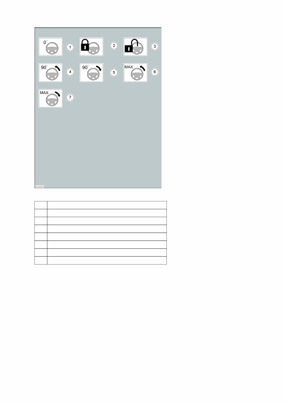
Item Description
1 Steering wheel in straight ahead position
2 Steerlumn lock locked
3 Steering column lock unlocked
4 Turn the steering wheel to the 90° left position
5 Turn the steering wheel to the 90° right position
6 Turn the steering wheel to the left-hand end position
7 Turn the steering wheel to the right-hand end position
Body Types
Body type symbols are used to identify different body configurations.
2011 E-Series Workshop Manual
Symbols Glossary 3
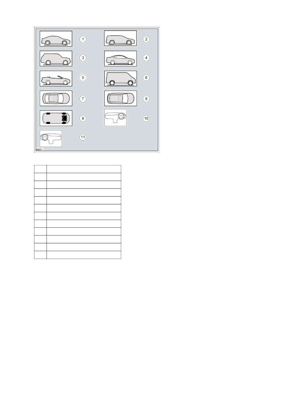
Item Description
1 3, 4, 5-door body style
2 Wagon body style
3 Sport utility vehicle body style
4 Coupe body style
5 Convertible body style
6 Van body style
7 3, 4, 5-door body style Top View
8 Wagon body style - Top View
9 Underbody view
10 Right-hand drive (RHD) vehicle
11 Left-hand drive (LHD) vehicle
Gearshift lever and selector lever position symbols
Gearshift lever and selector lever position symbols are used to show the lever position that is required to be
selected to carry out a procedure step.
2011 E-Series Workshop Manual
Symbols Glossary 4
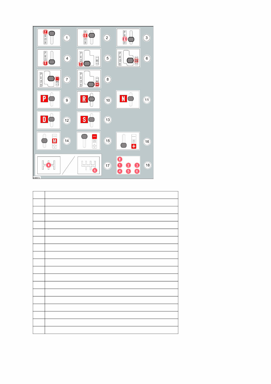
Item Description
1 Replaced by symbol 9
2 Replaced by symbol 10
3 Replaced by symbol 11
4 Replaced by symbol 12
5 Replaced by symbol 12
6 Replaced by symbol 14
7 Replaced by symbol 15
8 Replaced by symbol 16
9 Set the selector lever to the park (P) position
10 Set the selector lever to the reverse ( R ) position
11 Set the selector lever to the neutral (N) position
12 Set the selector lever to the drive (D) position
13 Set the selector lever to the drive (S) position
14 Set the selector lever to the drive (M) position
15 Set the selector lever to the drive (-) position
16 Set the selector lever to the drive (+) position
17 Set the gearshift lever to the neutral (N) position
18 Further gearshift lever positions that may appear in Illustrations
Screwdriver symbols
2011 E-Series Workshop Manual
Symbols Glossary 5
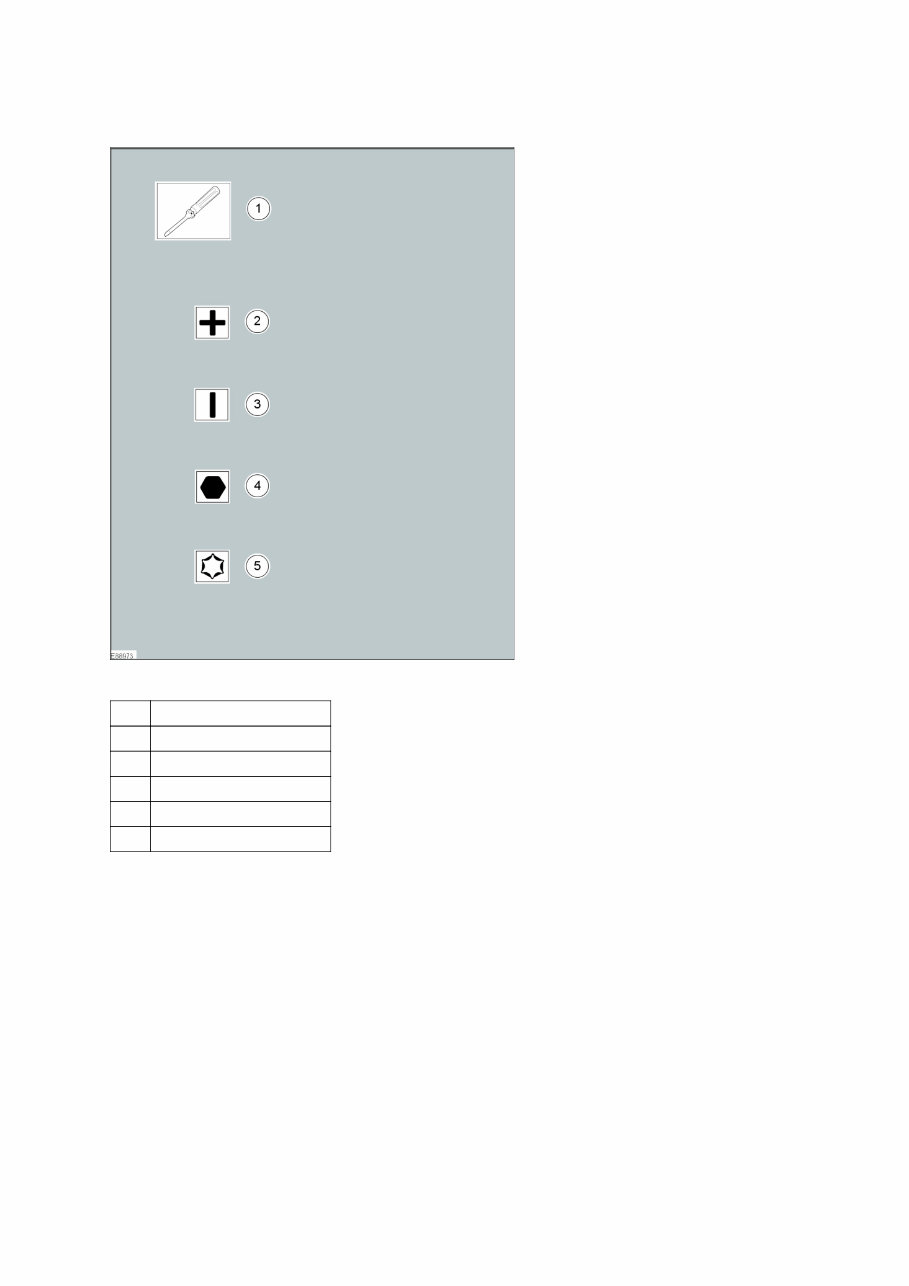
The screwdriver symbols are used to show which screwdriver bit is recommended to carry out a procedure
step.
Item Description
1 Screwdriver
2 Cross bladed screwdriver
3 Flat-bladed screwdriver
4 Hexagonal screwdriver
5 TORX screwdriver
Pliers Symbols
The plier symbols are used to show which pliers is recommended to carry out a procedure step.
2011 E-Series Workshop Manual
Symbols Glossary 6
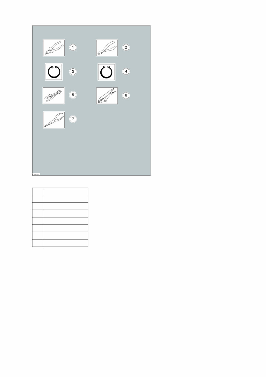
Item Description
1 Combination pliers
2 Side cutter pliers
3 Securing ring - inner
4 Securing ring - outer
5 Hose clamp pliers
6 Locking pliers
7 Long nose pliers
Drill Symbols
The drill symbols are used to show which type and size of drill bit is recommended to carry out a procedure
step.
2011 E-Series Workshop Manual
Symbols Glossary 7
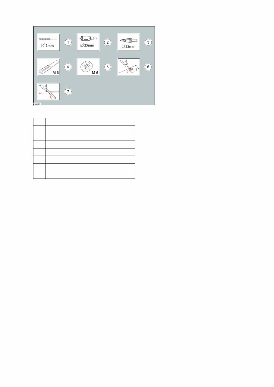
Item Description
1 Drill bit with a specified diameter
2 Hole saw with a specified diameter
3 Stepped drill bit with a specified diameter
4 Tap with a specified diameter
5 Die with a specified diameter
6 Scraper for circular holes
7 Scraper for straight edges
Cutting Tool Symbols
The cutting tool symbols are used to show which type of cutting tool is recommended to carry out a procedure
step.
2011 E-Series Workshop Manual
Symbols Glossary 8
You're Reading a Preview
What's Included?
Fast Download Speeds
Offline Viewing
Access Contents & Bookmarks
Full Search Facility
Print one or all pages of your manual
$41.99
Viewed 30 Times Today


Secure transaction
What's Included?
Fast Download Speeds
Offline Viewing
Access Contents & Bookmarks
Full Search Facility
Print one or all pages of your manual
$41.99
- This repair manual provides comprehensive troubleshooting and replacement procedures for the 2011 Ford E-450, including step-by-step instructions, clear images, and exploded-view illustrations.
- It is a valuable resource for both professional mechanics and DIY enthusiasts, offering manufacturer-recommended charts and procedures for vehicle maintenance and repair.
- Conveniently accessible in digital format, it eliminates the hassle of searching through numerous pages and allows for easy navigation, bookmarking, and printing if desired.
- Printable: Yes
- Language: English
- Compatibility: Suitable for various electronic devices, including PC, Mac, Android, and Apple smartphones and tablets.
- Requirements: Adobe Reader (free)
The digital manual is available in .PDF format.


