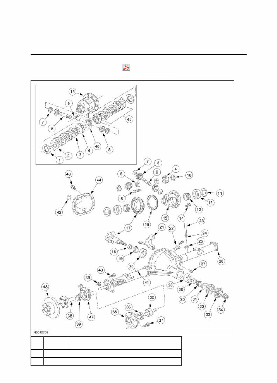
The axle assembly has the following features: An integral-type housing hypoid gear design (center of the pinion set below the centerline of the ring gear). The hypoid ring gear and pinion consists of a ring gear and an overhung drive pinion which is supported by 2 opposed tapered roller bearings. Drive pinion bearing preload is maintained by a drive pinion collapsible spacer on the drive pinion shaft and adjusted by the pinion nut. The axle housing consists of a cast center section with 2 steel tube assemblies and a stamped differential housing cover. The differential housing cover uses silicone sealant as a gasket. The differential pinion shaft is retained by a threaded differential pinion shaft lock bolt assembled to the differential assembly. The differential assembly is mounted in the axle housing between 2 opposing differential bearings that are retained in the axle housing by removable differential bearing caps. Differential bearing preload and differential ring and pinion backlash are adjusted by differential bearing shims located between the differential bearing cups and the axle housing. Axle identification is on an embossed metal tag bolted to the differential housing cover. For additional information, refer to Section 205 - 00 . 42 — Axle identification tag (part of 4001) 43 4346 Differential housing cover bolt (12 required) 44 4033 Differential housing cover 45 4947 Differential clutch pack 46 4214 Differential clutch spring 47 2C220 Rear wheel disc brake adapter (2 required) 48 2C206 Brake disc (2 required) Page 3 of 3 2005 F-150 Workshop Manual
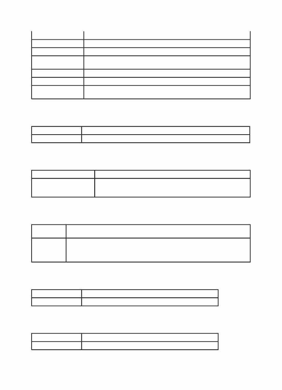
Rear Drive Axle and Differential Printable View (224 KB) Inspection and Verification The technician should have a thorough knowledge of driveline system operation and accepted general driveline guidelines to detect any problems. A gear driven unit will produce a certain amount of noise. Some noise is acceptable and audible at certain speeds or under various driving conditions. Certain conditions, such as road conditions and weather, will amplify normal vehicle noise. Certain rear axle and driveline concern symptoms are also common to the engine, transmission, rear wheel bearings and tire. For this reason, be sure the cause of the concern is in the axle before repairing or installing any axle components. The following is a guide to diagnose a driveline concern: Verify and document the customer concern. Perform a preliminary investigation. Road test the vehicle. Find the cause of the problem. Inspect the components. 1. Verify and document the customer concern. 1. When was it first noticed? 2. Did it appear suddenly or gradually? 3. Did anything unusual occur that would coincide with it or precede it? 4. Has the driveline system been repaired before or new components installed? Check the vehicle service record. Note any repairs other than driveline, such as brakes or suspension. 5. Are there any special conditions affecting the concern or will alter the concern? For example, road speed type of road drive mode temperature vehicle loaded or unloaded 6. Is the condition constant or intermittent? Can the concern be duplicated at any time? 7. Check for TSBs, SSM and OASIS messages. SECTION 205-02B: Rear Drive Axle/Differential — Ford 9.75-Inch Ring Gear 2005 F-150 Workshop Manual DIAGNOSIS AND TESTING Procedure revision date: 01/27/2005 Special Tool(s) Dial Indicator Gauge with Holding Fixture 100-002 (TOOL-4201-C) or equivalent Page 1 of 8 2005 F-150 Workshop Manual
2. NOTE: If the inspection reveals an obvious concern, repair the vehicle. Do a preliminary investigation. Visually inspect for obvious signs of damage. 1. Inspect the driveshaft: for build up of any foreign material. for damage, such as a bent tube or missing weights. U-joints or flex couplers for wear or damage. 2. Inspect the axle: for signs of leakage at the drain or fill plug, differential seal, vent or halfshaft seals. a plugged vent or vent tube will cause a leak. for damage, such as cracks, bent halfshafts or dented rear cover. for missing fasteners. 3. Inspect other suspect components/systems: inspect the halfshaft assemblies for damaged CV joints or torn CV boots inspect the suspension for broken springs, damaged shock absorbers and worn suspension bushings. inspect the rear brake components — lines, cables and calipers. inspect the tires; are they in good condition and do they match? 3. NOTE: A road test is necessary for any customer concern of noise or vibration. Road test the vehicle. 1. During the road test, use the following driving methods to diagnose the problem. Is the concern most noticeable: from a stop? on shifts from REVERSE to DRIVE? on turns? sweeping type turn. tight turn (to the stop). in DRIVE? accelerating the vehicle, definite throttle depression, applying engine torque? in CRUISE? maintain a constant speed with the throttle applied? in COAST? decelerating with the throttle closed? 2. Record when the concern occurs. Write down the kph (mph) range at which the noise/vibration occurs. 4. Find the cause of the problem. 1. Compare the inspection and road test results with the following chart. 2. Use the following diagnostic routine chart to identify the probable cause and know what corrective actions should be taken to repair the component/vehicle, and to prevent a reoccurrence. Diagnostic Routine Chart Condition Action · Fluid loss · GO to Diagnostic Routine — Fluid Loss · Noise louder on turns (sweeping turn) · GO to Diagnostic Routine — Noise Louder On Turns (Sweeping) · Axle noise (growl) a in tight turn · GO to Diagnostic Routine — Noise (Growl) In Tight Turn · Axle noise (chatter/shudder) a in tight turn, limited slip differential · GO to Diagnostic Routine — Noise (Chatter/Shudder) In Tight Turns, Limited Slip Differential · Axle noise (whine) a in all or more than · GO to Diagnostic Routine — Noise (Whine) Page 2 of 8 2005 F-150 Workshop Manual
a. Refer to Section 100 - 04 for a glossary of noise-related terms. 5. NOTE: If the conclusion of the road test points to an axle center section (ring and pinion or differential case) concern, carry out a visual inspection of the axle. Inspect the axle components. 1. Remove the differential housing cover. Drain the axle lubricant through a white cloth. Check the fluid for: any foreign material. metal particles. burnt odor. 2. NOTE: When inspecting the axle, do not clean the components immediately. Cleaning may remove diagnostic evidence. Inspect the axle components. Look for: loose fasteners. notches or visible steps or grooves created by wear. pitting or cracking along gear contact lines. scuffing or deformations. discolorations. nicks or ridges on gear teeth. Clean the axle components for inspection. Remove as much lubricant as possible with clean solvent. Wipe the components or blow them dry with compressed air. Re-inspect for: loose fasteners. notches or visible steps or grooves created by wear. pitting or cracking along gear contact lines. scuffing or deformations. discolorations. nicks or ridges on gear teeth. Check backlash and carry out a ring and pinion pattern test. Refer to Checking Differential Ring Gear Backlash and Checking Tooth Contact Pattern and Condition of the Ring and Pinion in this section. Diagnostic Routines one drive mode In All Or More Than One Drive Modes · Axle noise (tick/click) a in all or more than one drive mode (drive, cruise, coast) · GO to Diagnostic Routine — Noise (Tick/Click) In All Or More Than One Drive Modes · Axle noise (howl/moan) a in all or more than one drive mode (drive, cruise, coast) · GO to Diagnostic Routine — Noise (Howl/Moan) In All Or More Than One Drive Modes · Axle noise (clunk) a on changes in speed or direction of power · GO to Diagnostic Routine — Noise (Clunk) On Changes In Speed Or Direction Of Power · Vibration · For additional information on driveline vibration diagnostics, REFER to Section 100 - 04 . Diagnostic Routine — Fluid Loss Page 3 of 8 2005 F-150 Workshop Manual
Possible Component Reference/Action · Vent · CLEAN the axle vent and vent hose. · Overfilled axle · CHECK the lubricant level for specific amount. · Fill plug · CLEAN the area around the plug. REMOVE the plug. APPLY pipe sealant and INSTALL the plug. · Halfshaft oil seal · INSTALL a new halfshaft oil seal. · Pinion seal · INSTALL a new pinion seal. · Differential housing cover · RESEAL the differential housing cover. Diagnostic Routine — Noise Louder on Turns (Sweeping) Possible Component Reference/Action · Wheel end bearing · CHECK the wheel end bearing for wear or damage. INSTALL a new bearing. Diagnostic Routine — Noise (Growl) In Tight Turn, Conventional Differential Possible Component Reference/Action · Differential side gears and differential pinion gears · Disassemble the differential carrier. INSPECT the differential case assembly. INSTALL new side gears and differential pinion gears or case assembly. Diagnostic Routine — Noise (Chatter/Shudder) In Tight Turns, Limited Slip Differential Possible Component Reference/Action · Clutch pack · VERIFY the condition. With the vehicle in cold startup, MAKE SURE that the vehicle is in 2WD, to isolate the rear axle. TURN the wheel fully right (or fully left) and then ACCELERATE the vehicle. If the condition is verified to be in the rear axle, REMOVE and INSTALL new clutch packs. Diagnostic Routine — Noise (Whine) In All Or More Than One Drive Modes Possible Component Reference/Action · Axle ring and pinion · REMOVE and INSTALL a new ring gear, pinion and bearings. Diagnostic Routine — Noise (Tick/Click) In All Or More Than One Drive Modes Possible Component Reference/Action · Axle ring and pinion · REMOVE and INSTALL a new ring gear, pinion and bearings. Page 4 of 8 2005 F-150 Workshop Manual
Checking Differential Ring Gear Backlash 1. Remove the differential housing cover. 2. Using a suitable dial indicator and the special tool, measure and record the differential ring gear backlash in 4 opposing points on the ring gear. Checking Tooth Contact Pattern and Condition of the Ring and Pinion There are 2 basic types of conditions that will produce ring and pinion noise. The first type is a howl or chuckle produced by broken, cracked, chipped, scored or forcibly damaged gear teeth and is usually quite audible over the entire speed range. The second type of ring and pinion noise pertains to the mesh pattern of the gear pattern. This gear noise can be recognized as it produces a constant pitch or whine. Ring and pinion noise tends to peak in a narrow speed range or ranges, and will tend to remain constant in pitch. NOTE: In the following steps, the movement of the contact pattern along the length is indicated as toward the "heel" or "toe" of the differential ring gear. Diagnostic Routine — Noise (Howl/Moan) In All Or More Than One Drive Modes Possible Component Reference/Action · Axle bearings · INSPECT differential and pinion bearings. INSTALL new bearings. Diagnostic Routine — Noise (Clunk) On Changes In Speed Or Direction Of Power Possible Component Reference/Action · Axle and Pinion System · Measure total backlash. If end play and total backlash are within specification, INSTALL a new differential case assembly. · Differential pinion shaft · INSTALL a new differential pinion shaft and pin. · Pinion Bearings · INSTALL new pinion and differential bearings and bearing cups. Diagnostic Routine — Vibration Possible Component Reference/Action · For additional information on driveline vibration, REFER to Section 100 - 04 . Page 5 of 8 2005 F-150 Workshop Manual
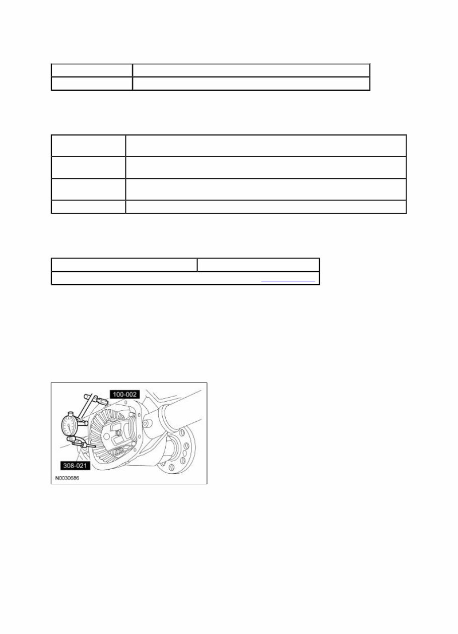
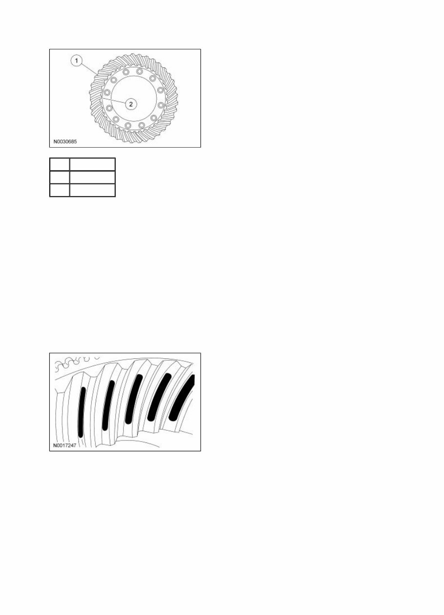
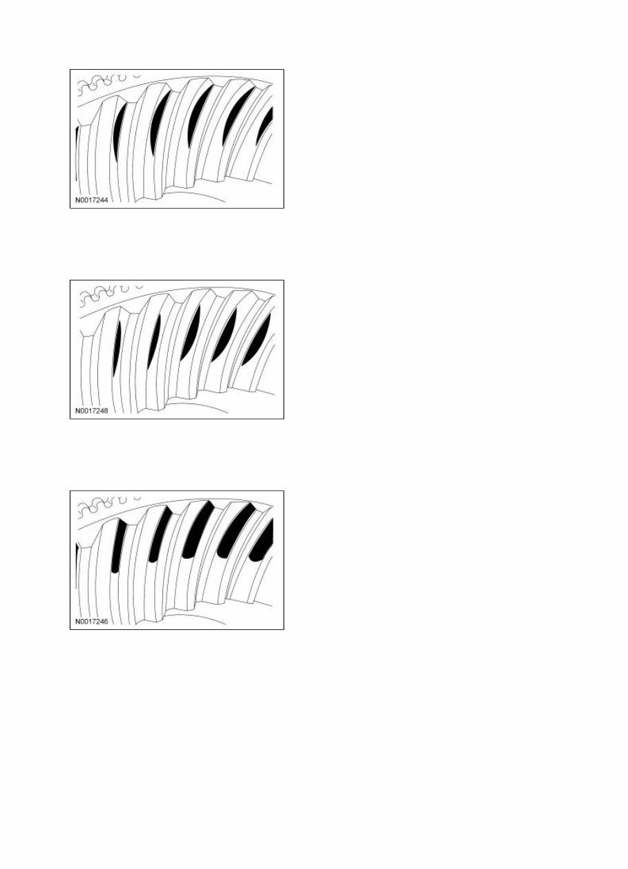
Apply a marking compound to a third of the gear teeth on the differential ring gear. Rotate the differential ring gear several complete turns in both directions until a good, clear tooth pattern is obtained. Compare the contact patterns on the ring gear teeth with the following illustrations. Good Contact Pattern Pattern inspection allows the technician to detect gross errors in set up prior to complete assembly of the differential assembly. Pattern contact should be within the primary area of the ring gear tooth section. Avoid narrow or hard contact with the outer perimeter of the ring gear tooth. Pattern inspection should be on the drive side of the tooth. Correct assembly of the drive pattern will result in satisfactory coast performance. NOTE: If a gross pattern error is detected with the correct backlash, check the pinion shim selection. Good Contact Pattern Low Contact Pattern That Is Contacting More Toward the Heel Gross Pattern Error Item Description 1 Heel 2 Toe Page 6 of 8 2005 F-150 Workshop Manual
High, Thin Contact Pattern In the Center Of the Tooth Gross Pattern Error Thick Contact Pattern That Is Contacting Tooth Toward the Heel Gross Pattern Error Thick Contact Pattern That Is Contacting Tooth Toward the Toe Gross Pattern Error Page 7 of 8 2005 F-150 Workshop Manual
Whether you're a first time mechanic or a seasoned repair technician, crucial service data, repair procedures, maintenance, assembly and disassembly service procedures are a requirement for the proper mechanical flow of an operation. A service repair manual doesn't become a simple guide for the mechanic but rather a essential tool of knowledge.
This workshop manual contains fully detailed step-by-step repair procedures with hundreds of very high quality photos and illustrations to guide you through any repair, maintenance, overhaul, service specifications or troubleshooting procedure. This repair manual will give you the knowledge and experience you need to perform simple basic maintenance or more complicated service procedures like an engine overhaul. Covers every thing you will ever need to know to fix anything and everything possible. You will not find a better manual any where on the Internet.
This is the same service manual provided to Ford/Lincoln dealers to work on your vehicle, it is the ultimate workshop manual you can buy, period. This high resolution manual has easy to use menus and is keyword searchable and fully printable. Easily browse the manual via bookmarks, zoom in/out of specific pages. Print the section you require, bring it out in your garage and once you've finished the job, simply bin them.
NOTE: This manual is approximately 5.9GB in size. If you have a slow internet connection, we highly recommend you purchase the DVD-R option above. This workshop manual is run in a virtual version of Windows XP via VMWare Player. All instructions are included.