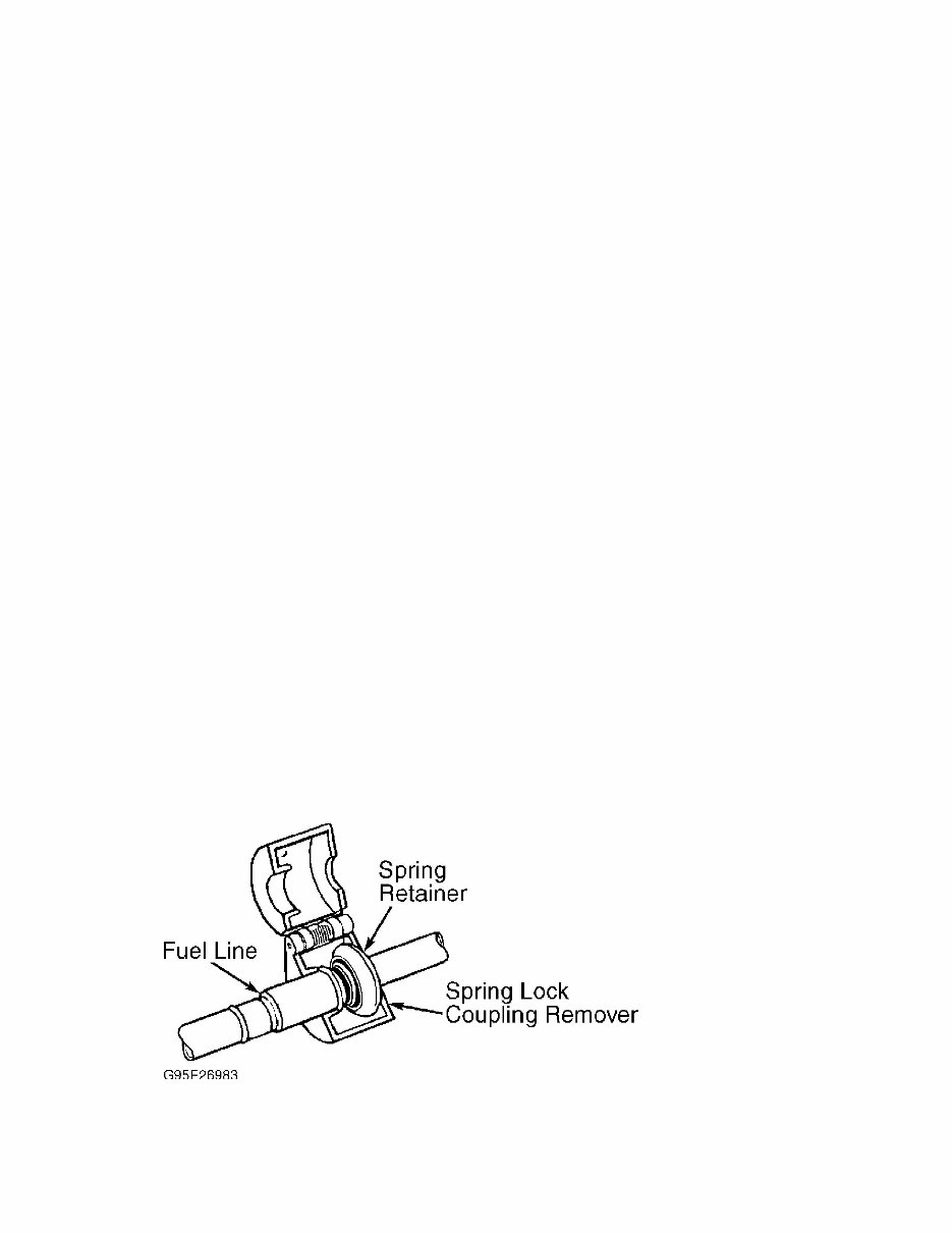
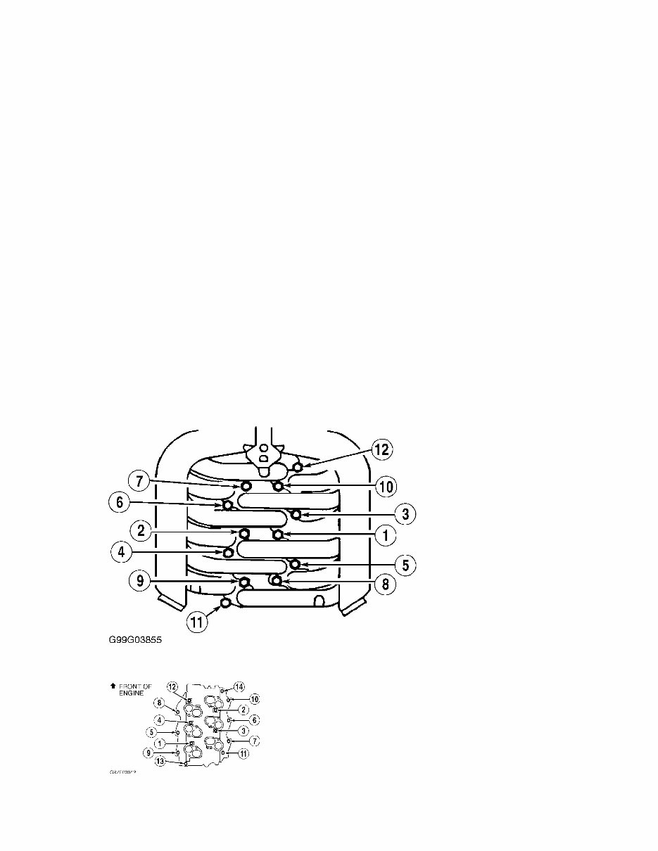
4.2L V6 - VIN [2] Article Text (p. 4) 1998 For 3) Remove headlight and side marker assemblies. Remove power steering cooler and auxiliary transmission cooler. Remove power steering cooler mounting brackets. Remove A/C condenser, and plug openings. Disconnect hood latch cable, and remove hood latch assembly. 4) Disconnect positive battery cable from power distribution box, and position aside. Remove power steering reservoir retaining bolts, and position aside. Remove upper and lower core support. Remove oil dipstick tube. Remove upper and lower intake manifolds. See INTAKE MANIFOLD. 5) Disconnect necessary harness and ground connections. Remove accessory drive belt. Disconnect low-pressure hose at power steering pump. Unbolt power steering pump, and position aside. Remove lower radiator hose. Disconnect A/C manifold at compressor, plug openings, and position aside. Disconnect A/C high-pressure hose at evaporator, and plug openings. 6) Raise and support vehicle. Drain engine oil. Remove starter. Remove torque converter nuts. Remove oil pan-to-transmission bolts. Disconnect exhaust pipes at exhaust manifolds. Disconnect shift cable bracket. Remove engine mount nuts. 7) Lower vehicle. Support transmission. Remove transmission dipstick tube. Install engine lifting equipment. Remove transmission- to-engine retaining bolts. Remove engine. Installation 1) To install, reverse removal procedure. Replace torque converter nuts with NEW ones. Tighten all bolts to specification. See TORQUE SPECIFICATIONS. 2) When installing fuel lines, fit NEW fuel resistant "O" rings (Brown) on fuel lines. Lightly coat "O" rings with clean engine oil before installing. Clean fittings, and replace garter spring (if necessary). 3) Adjust all control cables and fluid levels. Refill cooling system. Evacuate and recharge A/C system. INTAKE MANIFOLD Removal 1) Disconnect negative battery cable. Remove air cleaner outlet tube. Disconnect spark plugs wires and harness connectors at ignition coil. Disconnect control cables from throttle body. Remove throttle body control cable bracket, and position aside. 2) Disconnect necessary vacuum and water lines. Disconnect necessary harness connectors and ground cables. Remove engine vacuum regulator from intake manifold. Remove upper intake manifold retaining bolts. Remove upper intake manifold and gasket. 3) Disconnect fuel injector harness connectors. Disconnect EGR manifold from EGR valve. Remove IMRC. Release fuel pressure and disconnect fuel lines. See FUEL PRESSURE RELEASE & FUEL LINE CONNECTIONS. 4) Mark position for installation, remove lower intake manifold retaining bolts in reverse order. See Fig. 3. Remove lower intake manifold and gaskets.
4.2L V6 - VIN [2] Article Text (p. 8) 1998 Ford belt. Remove cooling fan and fan shroud. Raise and support vehicle. Mark pulley and damper position. Remove crankshaft pulley. Remove damper bolt. 2) Install Crankshaft Damper Remover (T58P-6316-D) and Crankshaft Damper Remover Adapter (T82L-6316-B). Remove damper. Using Seal Remover (T92C-6700-CH), remove oil seal from front cover. Installation To install, reverse removal procedure. Lubricate oil seal bore and seal lip with engine oil before installing. Apply silicone sealant to keyway of crankshaft damper before installing. Install seal. Tighten bolts to specification. See TORQUE SPECIFICATIONS. FRONT COVER WARNING: Air suspension system must be shut off prior to hoisting, jacking or towing an air suspension vehicle. Air suspension switch is located behind right kick panel. Failure to do so can result in accidental deflation or inflation of air springs, which may cause vehicle to shift during servicing. CAUTION: When battery is disconnected, vehicle computer and memory systems may lose memory data. Driveability problems may exist until computer systems have completed a relearn cycle. See COMPUTER RELEARN PROCEDURES article in GENERAL INFORMATION before disconnecting battery. Removal (Pickup) 1) Disconnect the battery ground cable, remove air cleaner assembly. 2) Raise vehicle, drain coolant from radiator, drain the engine oil. 3) Lower vehicle, remove upper radiator hose. Remove the fan shroud and the lower radiator hose. Remove the accessory drive belt. 4) Raise vehicle, remove the 2 nuts holding the Crankshaft (CKP) sensor shield in place and remove the shield. Disconnect both the Knock (KS) sensor and CKP sensor harness connectors. Position wiring harness aside. 5) Remove transmission line support bracket bolt. Remove power steering support bracket bolts. Remove the A/C compressor mounting bracket nuts and position the A/C compressor aside. 6) Mark crankshaft pulley and damper position. Remove crankshaft pulley and damper. See FRONT COVER OIL SEAL. 7) Remove front oil pan bolts that intersect with the front cover. Remove the Allen-head(R) bolt at front engine cover. 8) Lower vehicle, remove the supply tube heater hoses. Detach wiring harness from the outlet tube and position aside. 9) Remove the heater water outlet tube (remove bolt). Remove water pump. See WATER PUMP. 10) Remove Cam Position Synchronizer. See CAMSHAFT SYNCHRONIZER. 11) Remove the 4 water pump mounting studs.
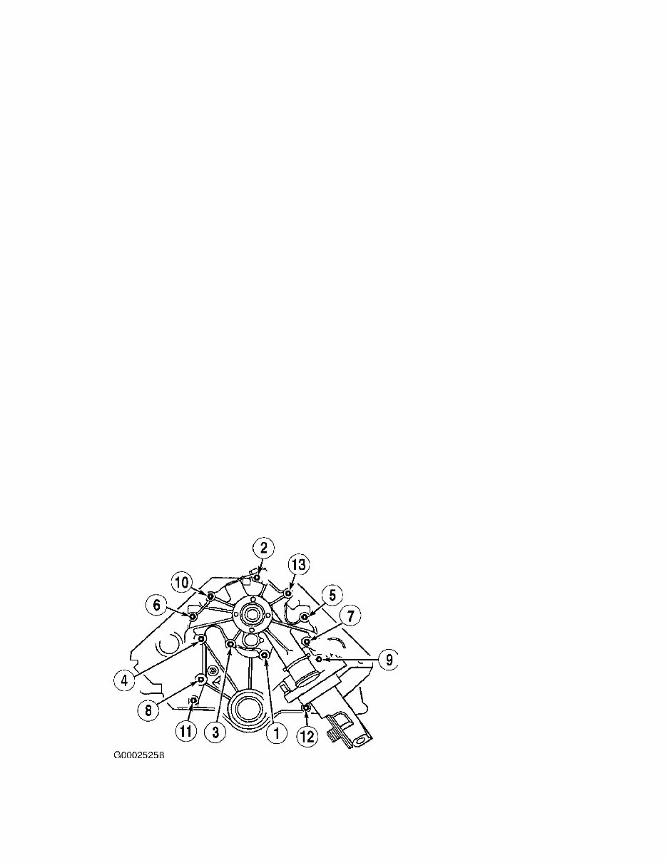
4.2L V6 - VIN [2] Article Text (p. 9) 1998 Ford Econoline E25 CAUTION: Failure to remove Cap Screw which may be over looked, may damage the cover if not removed. 12) Remove engine front cover stud bolts and bolt. Remove CAP SCREW. See Fig. 6 13) Slide the front cover off the dowels, remove the gasket and discard. Installation (Pickup) CAUTION: Failure to prevent foreign material from entering the engine block or front engine cover will result in engine damage. To prevent damage to engine components, seal coolant and oil passages. Prevent foreign material from entering the oil pan. CAUTION: DO NOT use a surface conditioning pad or any other type of fibrous abrasive disc to clean gasket surfaces. Failure to follow these directions will result in engine damage. 1) Clean off surfaces of the block, front engine cover and exposed oil pan flange. NOTE: If sealant (F6AZ-19562-A) is exposed for longer than 7 minutes, wipe off sealant and re-apply. 2) Install front engine cover gasket, apply sealant (F6AZ- 19562-A) to base of gasket where oil pan and block come together. Apply a bead of sealant in center of oil pan flange and around bolt holes. Apply a thin layer of sealant to front cover gasket mating surface (DO NOT over apply the sealant). NOTE: There are 13 fasteners securing the front engine cover. The CAP SCREW will be identified as fastener No. 12. DO NOT tighten the CAP SCREW (No. 12) in the first tightening sequence. 3) Tighten fasteners in 3 stages, as follows: * Starting with bolt at about the 6 o'clock position (identified as bolt No. 1), tighten fasteners 1-11 and 13 in sequence to 16 Ft. lbs. (22 N.m). See Fig. 6. NOTE: Apply a small amount of loctite(R) to threads of cap screw (do not over apply compound). * Tighten CAP SCREW (No. 12) to 89 INCH. lbs. (10 N.m). * Tighten all fasteners (except Cap Screw No. 12) an additional 90 degrees, in sequence. 4) Apply a bead of sealant in center of oil pan flange and around bolt holes. Apply a thin layer of sealant to front cover gasket
4.2L V6 - VIN [2] Article Text (p. 10) 1998 For mating surface (DO NOT over apply the sealant). Install front cover. 5) Install the front engine cover. Tighten bolts to 15-20 Ft. lbs. (20-30 N.m). 6) Install water pump mounting studs, tighten to 15-20 Ft. lbs. (20-30 N.m). 7) Install Cam Position Synchronizer. Install water pump. See WATER PUMP. Install the heater water outlet tube, tighten to 71-97 INCH. lbs. (8-11 N.m). 8) Attach the wiring to the outlet tube, install both supply tube heater hoses. 9) Raise vehicle, install Allen-head(R) bolt, tighten to 15- 20 Ft. lbs. (20-30 N.m). Install oil pan bolts, tighten to 80-106 INCH. lbs. (9-12 N.m). 10) Install crankshaft pulley and damper. See FRONT COVER OIL SEAL and TORQUE SPECIFICATIONS. 11) Install A/C compressor mounting bracket nuts, tighten to 30-40 Ft. lbs. (40-45 N.m). 12) Install power steering support bracket bolts. Install transmission line support bracket bolt. 13) Connect (CKP) sensor and Knock sensor harness connectors. Install the (CKP) sensor shield. 14) Lower vehicle, install accessory drive belt. 15) Install the lower radiator hose, the fan shroud and upper radiator hose. 16) Refill coolant system, refill the engine oil. Ensure oil drain plug has been tightened. 17) Reconnect the battery ground cable, install air cleaner assembly. 18) Start vehicle and check for leaks. Fig. 6: Front Cover Tightening Sequence Courtesy of Ford Motor Co. Removal (Van) 1) Disconnect negative battery cable.
1992-2010 Ford Econoline (E-150/E-250/E-350) Service & Repair Manual
Engines covered:
4.2 L (256 cu in) Essex V6
4.6 L (281 cu in) Triton V8
4.9 L (300 cu in) Truck Six I6
5.0L (302 cu in) Windsor V8
5.4 L (330 cu in) Triton V8
5.8 L (351 cu in) Windsor V8
6.8 L (415 cu in) Triton V10
7.5 L (460 cu in) 385/Lima V8
This truck repair manual is a valuable resource for both professional mechanics and DIY enthusiasts. It contains comprehensive troubleshooting and replacement procedures provided by the manufacturer, along with step-by-step instructions, clear images, and exploded-view illustrations.
Regular maintenance is essential for the durability of your truck. Over time, certain parts will wear out and require replacement. This manual provides the manufacturer's recommended troubleshooting charts and replacement procedures, enabling you to save on repairs, enhance your vehicle's reliability, and minimize visits to the repair shop.
Featuring step-by-step instructions, exploded-view illustrations, and clear images, this manual eliminates the need to search through numerous pages for specific information. It offers a convenient digital format, allowing easy access, searchability, and portability on various electronic devices, including PCs, Mac computers, smartphones, and tablets.
Additionally, the manual is printable and compatible with Adobe Reader, making it accessible for users who prefer physical copies. The language used is English, ensuring broad accessibility for users.
Recently Viewed
5,521,897Happy Clients
2,594,462eManuals
1,120,453Trusted Sellers
15Years in Business
Price:
Actual Price:
1992-2010 Ford Econoline (E-150/E-250/E-350) Service & Repair Manual