31-01-1
GROUP
31 CHARGING SYSTEM
(10000)
SECTION TITLE PAGE SECTION TITLE PAGE
ALTERNATOR-INTEGRAL REGULATOR-EXTERNAL FAN CHARGING SYSTEM-SERVICE ................................ 31-o1·1
TyPE ......................................................................... 31·17·1 IGNITION SWITCH ..................................................... 31-20-1
BATTERIES ............................................................... 31-02·1
SECTION 31-01 Charging System-Service
SUBJECT PAGE SUBJECT PAGE
DESCRIPTION AND OPERATION ................................ 31·01·1 SPECIFICATIONS ...................................................... 31-01·9
DIAGNOSIS ............................................................... 31·01·1 TESTING ................................................................... 31 ·01·4
SPECIAL SERVICE TOOLS ......................................... 31·01·9 VEHICLE APPLICATION ............................................. 31·01·1
VEHICLE APPLICATION
Capri.
DESCRIPTION AND OPERATION
The alternator charging system is a negative ground
system consisting of an alternator with an integral
regulator, a charge indicator lamp, a storage battery,
and associated wiring.
The integral regulator is solid·state.lt is mounted onto
the rear of the alternator and contains the alternator
brushes.
DIAGNOSIS
Battery and charging system trouble is frequently due
to physical rather than electrical factors including
loose or corroded wiring connections, damaged
wiring, slipping drive belts, dirty battery surfaces and
terminals, or poor maintenance.
Thoroughly inspect the system.
1. Make sure battery terminals and cable
connections are clean and tight. Refer to Section
31-02.
2. Inspect battery cable connections to starter and
engine ground for surface dirt or foreign matter.
3. Check alternator drive belt for glazing or cracking
which may have been caused by belt slippage. If
sides of belt are shiny or feel slick, replace them.
Check belt tension. Refer to Section 27 -02 for
belt replacement or tension adjustment.
4. Make sure that top surface of battery is clean and
free of moisture or foreign matter.
Charging system troubles such as low alternator
output, no alternator output (indicated by the indicator
lamp being on while the engine is running), or alternator
output voltage too high, require testing of both the
alternator and the voltage regulator.
Copyright © 1990, Ford Motor Co. www.techcapri.com
31-01-2 Charging System-Service 31-01-2
DIAGNOSIS (Continued)
Voltage regulator failures are usually not recognized
except by the direct affect on the alternator output.
and eventual battery discharge. The regulator is the
control valve for the alternator. It protects the battery
by preventing excessive voltage output.
Discharge of the battery to ground through the
alternator is prevented by the diodes of the alternator
which permit current flow in one direction (to the
battery) only.
A discharged battery is not always due to a problem in
the charging system. Excessive use of lamps and
accessories while the engine is either off or running at
low idle. corroded battery cables and connectors. low
acid level in the battery. or prolonged disuse of the
battery. which would permit self-discharge are all
possible reasons which should be considered when a
battery is run down or low in charge.
NOTE: Always determine the cause of failure as well
as making the repair.
1. Polarity and Connections. The alternator is for
use on negative ground electrical systems only.
Polarity cannot be reversed and any attempt to
do so will damage the alternator.
2. Installing Vehicle Battery. Reversed battery
connections will damage the alternator rectifiers.
When installing. first connect the positive
connector to the battery positive terminal and
then connect the negative connector to the
negative battery terminal.
3. Battery Charging. Disconnect the battery
negative cable to isolate the alternator from the
battery and external charging equipment.
4. Battery Connections. Never disconnect the
battery while the engine is running. Damage to
the rectifier and lor other electrical components
may occur. Using a slave battery to start the
engine and then reconnectil1g the original battery
while the engine is running must not be attempted.
Do not break or make any other connections in
the alternator circuit while the engine is running.
5. Alternator Main Output Cable.
• The cable connecting the alternator and the
battery has constant battery voltage even
when the engine is not running. Care must be
taken not to ground this cable if it should ever
be removed, or damage to the cable will occur.
• Never run the alternator with the main output
cable disconnected either at the alternator or
battery end while the field remains energized
or the rectifiers may be damaged.
6. Arc Welding. Isolate the control box and
alternator by disconnecting their wiring
connectors prior to performing any arc welding on
the vehicle.
7. lamps and Fuses Fall Prematurely, Short
Battery life. Other systems covered under this
heading are: battery uses excessive amount of
water; high battery charging rate. Check all
charging system wiring connections including the
regulator ground and battery sensing wire.
lighten or service as required. Check the
alternator voltage limiter setting. Replace if not to
specification.
8. Alternator Noisy. When diagnosing the
complaint of alternator noise. isolate the noise
area and make sure that the alternator is at fault
rather than the alternator belt. water pump. or
another part of the vehicle. Start the engine and
use a stethoscope or similar tool to isolate the
noise. An alternator bearing, water pump bearing
or belt noise is usually evidenced by a squealing
sound.
An alternator with a shorted diode will normally
whine (magnetic noise) and will be most
noticeable at idle speeds. Perform the alternator
output tests. If the output is approximately 10
amperes less than that specified. a shorted diode
is usually indicated.
To eliminate the belt(s} as the cause of noise,
check the belt(s} for bumps, apply a light spray of
water to the belt(s}. If the alternator belt is at
fault. adjust the belt to specification. or replace
the belt if necessary.
If the belt(s) is satisfactory and the noise is
believed to be in the alternator or water pump,
remove the alternator belt. Start the engine and
listen for the noise to be sure that the noise Is not
caused by another component. Use this test and
the sound detector test to isolate the noisy
component. If the noise Is traced to the
alternator, remove it and check bearings for play
or roughness.
9. Charge Indicator /Warning lamp Flickers.
This condition may be caused by loose or
damaged connections in the charging system
wiring harness, worn brushes. or improper brush
tension.
Copyright © 1990, Ford Motor Co. www.techcapri.com
31-01-3 Charging System-Service 31-01-3
DIAGNOSIS (Continued)
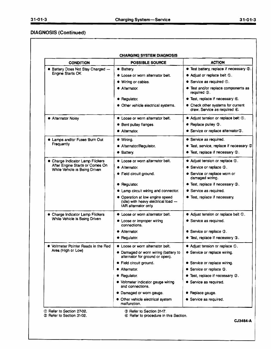
CHARGING SYSTEM DIAGNOSIS
CONDITION POSSIBLE SOURCE ACTION
• Battery Does Not Stay Charged -
• Battery.
• Test battery, replace if necessary <2J.
Engine Starts OK
• Loose or worn alternator belt.
• Wiring or cables.
• Alternator.
• Regulator.
• Other vehicle electrical systems.
• Adjust or replace belt (j).
• Service as required (j).
• Test and/or replace components as
required @.
• Test, replace if necessary @.
• Check other systems for current
draw. Service as required @.
• Alternator Noisy • Loose or worn alternator belt.
• Bent pulley flanges.
• Alternator.
• Adjust tension or replace belt (j).
• Replace pulley @.
• Service or replace alternator@.
• Lamps and/or Fuses Burn Out
Frequently
• Wiring.
• Alternator/Regulator.
• Battery.
• Service as required.
• Test, service, replace if necessary @
• Test, replace if necessary <2J.
• Charge Indicator Lamp Flickers • Loose or worn alternator belt. • Adjust tension or replace (j).
After Engine Starts or Comes On
While Vehicle is Being Driven
• Alternator.
• Field circuit ground.
• Regulator.
• Lamp circuit wiring and connector.
• Operation at low engine speed
(idle) with heavy electrical load -
IAR alternator onl)(
• Service or replace @.
• Service or replace worn or
damaged wiring.
• Test, replace if necessary @.
• Service as required.
• Test, replace if necessar)(
• Charge Indicator Lamp Flickers • Loose or worn alternator belt. • Adjust tension or replace belt (j).
While Vehicle is Being Driven
• Loose or improper wiring
connections.
• Alternator.
• Regulator.
• Service as required.
• Service or replace @.
• Test, replace if necessary @.
• Voltmeter Pointer Reads in the Red • Loose or worn alternator belt. • Adjust tension or replace (j).
Area (High or Low)
• Damaged or worn wiring (battery to
alternator for ground or open).
• Field circuit ground.
• Alternator.
• Regulator.
• Voltmeter indicator gauge wiring
and connections.
• Damaged or worn gauge.
• Other vehicle electrical system
malfunction.
• Service or replace wiring.
• Service or replace wiring.
• Service or replace @.
• Test, replace if necessary @.
• Service as required.
• Replace gauge.
• Service as required.
(j) Refer to Section 27"()2. @ Refer to Section 31·17.
(ID Refer to Section 31-02. @ Refer to procedure in this Section.
CJ3484·A
Copyright © 1990, Ford Motor Co. www.techcapri.com
Charging System-Service
TESTING
The following system test charts have been arranged
in a series to isolate the component or cause of a
charging system complaint.
Start at the beginning and continue through the test
steps even after the cause of the complaint is found.
This will rule out the possibility that the original
condition was not caused by more than one charging
system problem.
Copyright © 1990, Ford Motor Co. www.techcapri.com
31-01-5 Charging System-Service 31-01-5
TESTING (Continued)
CHARGING SYSTEM TEST
TEST STEP RESULT ACTION TO TAKE
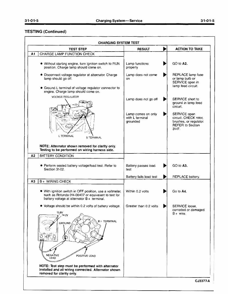
A1 CHARGE LAMP FUNCTION CHECK
• Without starting engine, turn ignition switch to RUN
position. Charge lamp should come on.
• Disconnect voltage regulator at alternator. Charge
lamp should go off.
• Ground L terminal of voltage regulator connector to
engine. Charge lamp should come on.
VOLTAGE REGULATOR
S TERMINAL
NOTE: Alternator shown removed for clarity only.
Testing to be performed on wiring harness side.
Lamp functions
properly
Lamp does not come
on
Lamp does not go off
Lamp comes on only
with L terminal
grounded
..
..
..
..
GO to A2.
REPLACE lamp fuse
or lamp bulb or
SERVICE open in
lamp feed circuit.
SERVICE short to
ground in lamp feed
circuit.
SERVICE open
circuit. CHECK rotor,
brushes, or regulator.
REFER to Section
31-17.
A2 BATTERY CONDITION
• Perform sealed battery voltagelload test. Refer to
Section 31-02.
Battery passes load
test
Battery fails load test
..
..
GO to A3.
REPLACE battery.
A3 B + WIRING CHECK
• With ignition switch in OFF position, use a voltmeter,
such as Rotunda 014-00407 or equivalent to test for
battery voltage at alternator B + terminal.
• Voltage should be within 0.2 volts of battery voltage.
Within 0.2 volts
Greater than 0.2 volts
..
..
Go to A4.
SERVICE loose,
corroded or damaged
B + wire.
NOTE: Test step must be performed with alternator
installed and all wiring connected. Alternator shown
removed for clarity only.
CJ3377-A
Copyright © 1990, Ford Motor Co. www.techcapri.com
31-01-6 Charging System-Service 31-01-6
TESTING (Continued)
CHARGING SYSTEM TEST - Continued
TEST STEP RESULT
."
ACTION TO TAKE
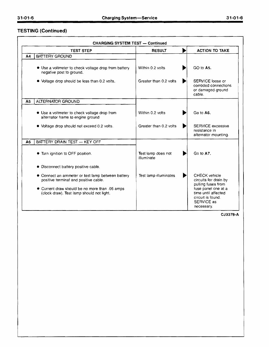
A4 I BATTERY GROUND
Within 0.2 volts
."
GO to AS.
negative post to ground.
• Use a voltmeter to check voltage drop from battery
Greater than 0.2 volts
."
SERVICE loose or
corroded connections
or damaged ground
cable.
• Voltage drop should be less than 0.2 volts.
AS J ALTERNATOR GROUND
Within 0.2 volts
."
Go to AS.
alternator frame to engine ground
• Use a voltmeter to check voltage drop from
Greater than 0.2 volts
."
SERVICE excessive
resistance in
alternator mounting.
• Voltage drop should not exceed 0.2 volts.
AS I BATTERY DRAIN TEST - KEY OFF
Test lamp does not
."
Go to A7.
illuminate
• Turn ignition to OFF position.
• Disconnect battery positive cable.
Test lamp illuminates
."
CHECK vehicle
positive termina! and positive cable.
• Connect an ammeter or test lamp between battery
circuits for drain by
pulling fuses from
fuse panel one at a
(clock draw). Test lamp should not light.
• Current draw should be no more than .05 amps
time until affected
circuit is found.
SERVICE as
necessary.
CJ3378-A
Copyright © 1990, Ford Motor Co. www.techcapri.com
31-01-7
31-01-7 Charging System-Service
TESTING (Continued)
CHARGING SYSTEM TEST - Continued
TEST STEP RESULT ACTION TO TAKE
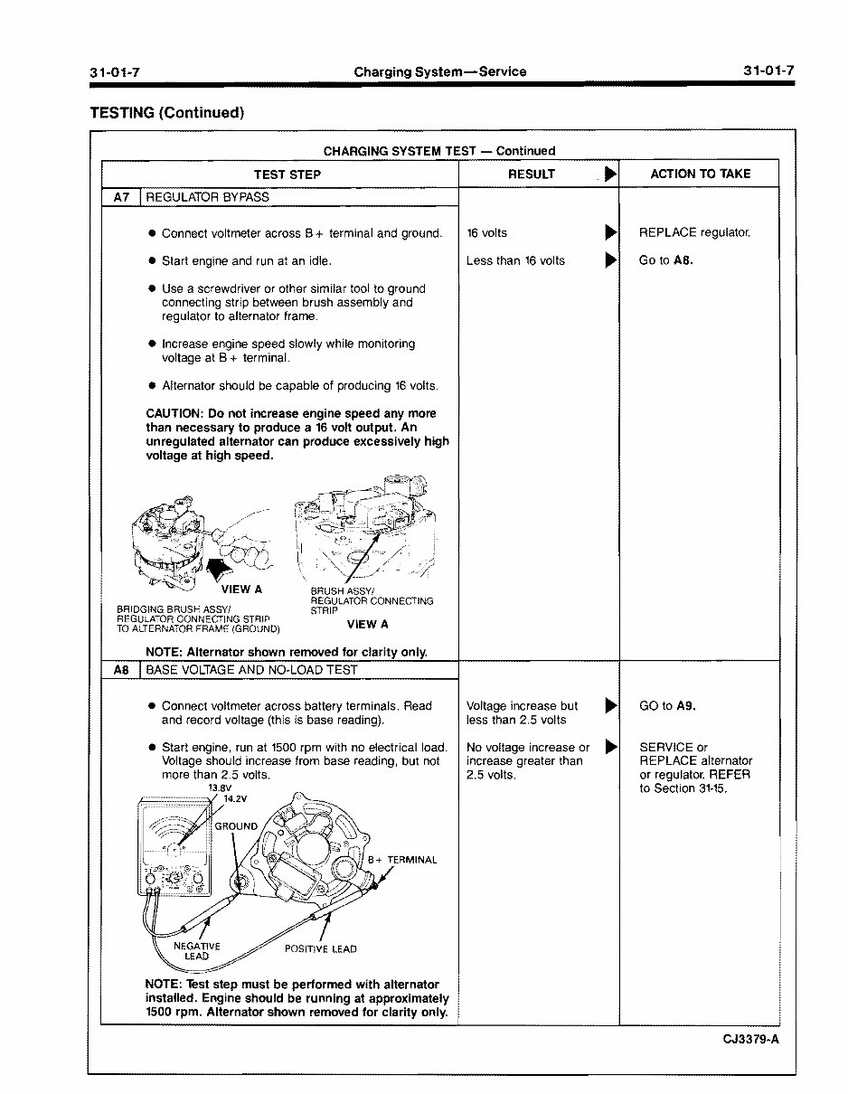
A7 REGULATOR BYPASS
16 volts
Less than 16 volts
REPLACE regulator.
Go to AS.
• Connect voltmeter across B + terminal and ground.
• Start engine and run at an idle.
• Use a screwdriver or other similar tool to ground
connecting strip between brush assembly and
regulator to alternator frame.
• Increase engine speed slowly while monitoring
voltage at B + terminal.
• Alternator should be capable of producing 16 volts.
CAUTION: Do not increase engine speed any more
than necessary to produce a 16 volt output. An
unregulated alternator can produce excessively high
voltage at high speed.
BRIDGING BRUSH ASSYI
REGULATOR CONNECTING STRIP
TO ALTERNATOR FRAME (GROUND)
BRUSH ASSYI
REGULATOR CONNECTING
STRIP
VIEW A
NOTE: Alternator shown removed for clarity only.
AS BASE VOLTAGE AND NO·LOAD TEST
Voltage increase but
less than 2.5 volts
No voltage increase or
increase greater than
2.5 volts.
GO to A9.
SERVICE or
REPLACE alternator
or regulator. REFER
to Section 31·15.
• Connect voltmeter across battery terminals. Read
and record voltage (this is base reading).
• Start engine, run at 1500 rpm with no electrical load.
Voltage should increase from base reading, but not
more than 2.5 volts.
NOTE: Test step must be performed with alternator
installed. Engine should be running at approximately
1500 rpm. Alternator shown removed for clarity only.
CJ3379·A
Copyright © 1990, Ford Motor Co. www.techcapri.com
31-01-8 Charging System-Service 31-01-8
TESTING (Continued)
CHARGING SYSTEM TEST - Continued
TEST STEP RESULT ACTION TO TAKE
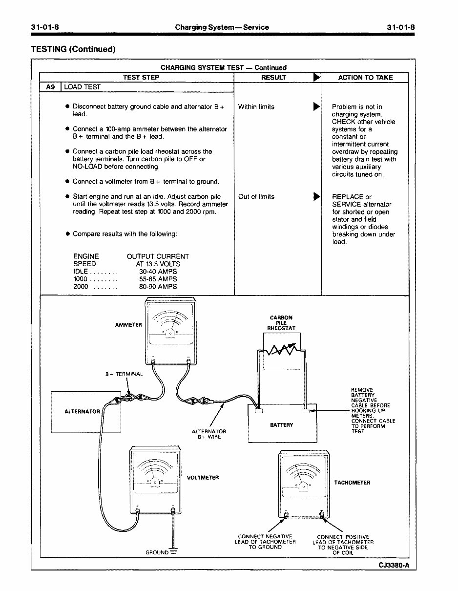
A9 LOAD TEST
Within limits
Out of limits
Problem is not in
charging system.
CHECK other vehicle
systems for a
constant or
intermittent current
overdraw by repeating
battery drain test with
various auxiliary
circuits tuned on.
REPLACE or
SERVICE alternator
for shorted or open
stator and field
windings or diodes
breaking down under
load.
• Disconnect battery ground cable and alternator B +
lead.
• Connect a 100-amp ammeter between the alternator
B + terminal and the B + lead.
• Connect a carbon pile load rheostat across the
battery terminals. Turn carbon pile to OFF or
NO· LOAD before connecting.
• Connect a voltmeter from B + terminal to ground.
• Start engine and run at an idle. Adjust carbon pile
until the voltmeter reads 13.5 volts. Record ammeter
reading. Repeat test step at 1000 and 2000 rpm.
• Compare results with the following:
ENGINE
SPEED
OUTPUT CURRENT
IDLE ....... .
1000 ....... .
2000 ...... .
AT 13.5 VOLTS
30·40 AMPS
55·65 AMPS
80-90 AMPS
AMMETER
ALTERNATOR
GROUND-=-
ALTERNATOR
B+ WIRE
VOLTMETER
CARBON
PILE
RHEOSTAT
BATTERY
CONNECT NEGATIVE
LEAD OF TACHOMETER
TO GROUND
REMOVE
BATTERY
NEGATIVE
CABLE BEFORE
0 ........ ---- HOOKING UP
METERS.
CONNECT CABLE
TO PERFORM
TEST
TACHOMETER
CONNECT POSITIVE
LEAD OF TACHOMETER
TO NEGATIVE SIDE
OF COIL
CJ3380·A
Copyright © 1990, Ford Motor Co. www.techcapri.com
31-01-9 Charging System-Service 31-01·9
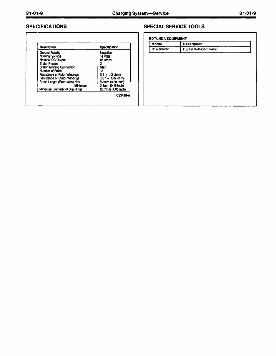
SPECIFICATIONS SPECIAL SERVICE TOOLS
ROTUNDA EQUIPMENT
Model Description
014-00407 Digital Volt-Ohmmeter
Deec:r!ptIon Specification
Ground Polarity Negative
Nominal '«Iltage 14 \tits
Nominal DC Output 85 amps
Stator Phases 3
Stator Winding Connection Star
Number 01 Poles 12
Resistance 01 Rotor Windings 2,6 ± ,13 ohms
Resistance 01 Stator Windings ,037 + 10% ohms
Brush Length (Prolrusion) New 9,8mm (0,39 Inch)
Minimum 3,Smm (0,15 Inch)
Minimum Diameter 01 Slip Rings 26.7mm (1.05 Inch)
CJ3485-A
Copyright © 1990, Ford Motor Co. www.techcapri.com
31-02-1 Batteries
SECTION 31-02 Batteries
SUBJECT PAGE
MAINTENANCE
Battery Cleaning ..••••••••.••••••••••.••..•.•.•.•.••.••••••••••• .... 31·02·6
Jump Starting ........................................................ 31·02·6
REMOVAL AND INSTALLATION
Battery .................................................................. 31·02·4
SERVICE
Battery Cable Clamp Spreader ............................... 31·02-5
Battery Cable Puller ............................................... 31-02-4
Battery Carrier ....................................................... 31·02-5
Battery Pliers ......................................................... 31·02·4
SUBJECT PAGE
SERVICE (Cont'd.)
Terminal Cleaning Brush ........................................ 31-02-5
Tools ..................................................................... 31-02-4
SPECIAL SERVICE TOOLS ......................................... 31-02-6
TESTING
Battery Capacity Test ............................................ 31-02-3
Battery Charging ................................................... 31-02-3
Battery Voltage Check ........................................... 31-02-1
VEHICLE APPLICATION ............................................. 31-02-1
VEHICLE APPLICATION
Capri.
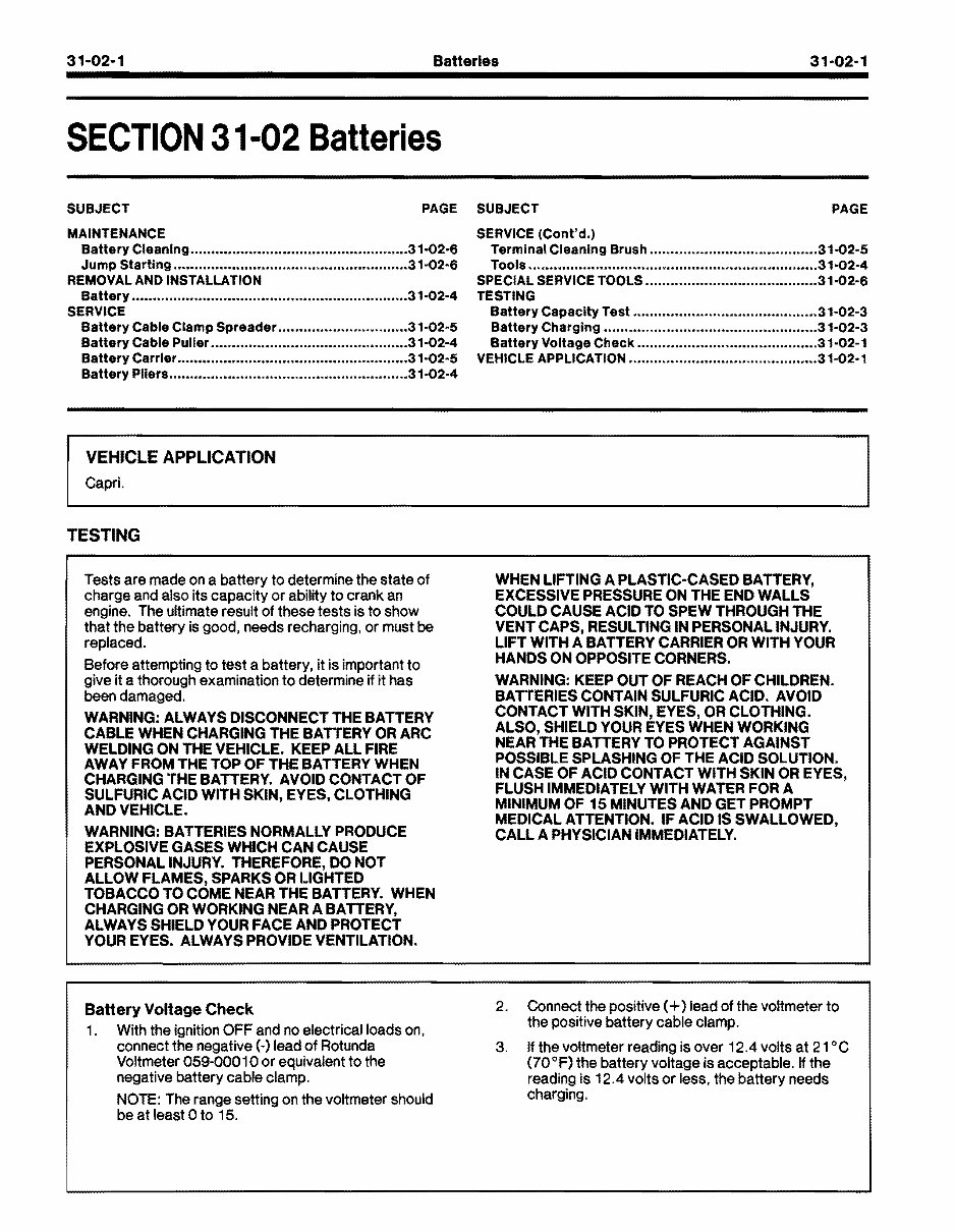
TESTING
Tests are made on a battery to determine the state of
charge and also its capacity or ability to crank an
engine. The ultimate result of these tests is to show
that the battery is good, needs recharging, or must be
replaced.
Before attempting to test a battery, it is important to
give it a thorough examination to determine if it has
been damaged.
WARNING: ALWAYS DISCONNECT THE BATTERY
CABLE WHEN CHARGING THE BATrERY OR ARC
WELDING ON THE VEHICLE. KEEP ALL FIRE
AWAY FROM 'rHE TOP OF THE BATTERY WHEN
CHARGING "rHE BATTERY. AVOID CONTACT OF
SULFURIC ACID WITH SKIN, EYES, CLOTHING
AND VEHICLE.
WARNING: BATTERIES NORMALLY PRODUCE
EXPLOSIVE GASES WHICH CAN CAUSE
PERSONAL INJURY. THEREFORE, DO NOT
ALLOW FLAMES, SPARKS OR I.lGHTED
TOBACCO TO COME NEAR THE BATTERY. WHEN
CHARGING OR WORKING NEAR A BATTERY,
ALWAYS SHIELD YOUR FACE AND PROTECT
YOUR EYES. ALWAYS PROVIDE VENTILATION.
Battery Voltage Check
1. With the ignition OFF and no electrical loads on,
connect the negative (-) lead of Rotunda
Voltmeter 059-000 1 a or equivalent to the
negative battery cable clamp.
NOTE: The range setting on the voltmeter should
be at least a to 15.
WHEN LIFTING A PLASTIC-CASED BATTERY,
EXCESSIVE PRESSURE ON THE END WALLS
COULD CAUSE ACID TO SPEW THROUGH THE
VENT CAPS, RESULTING IN PERSONAL INJURY.
LIFT WITH A BATTERY CARRIER OR WITH YOUR
HANDS ON OPPOSITE CORNERS.
WARNING: KEEP OUT OF REACH OF CHILDREN.
BATTERIES CONTAIN SULFURIC ACID. AVOID
CONTACT WITH SKIN, EYES, OR CLOTHING.
ALSO, SHIELD YOUR EYES WHEN WORKING
NEAR THE BATTERY TO PROTECT AGAINST
POSSIBLE SPLASHING OF THE ACID SOLUTION.
IN CASE OF ACID CONTACT WITH SKIN OR EYES,
FLUSH IMMEDIATELY WITH WATER FOR A
MINIMUM OF 15 MINUTES AND GET PROMPT
MEDICAL ATTENTION. IF ACID IS SWALLOWED,
CALL A PHYSICIAN IMMEDIATELY.
2. Connect the positive (+) lead of the voltmeter to
the positive battery cable clamp.
3. Ifthe voltmeter reading is over 12.4 volts at 21°C
(70°F) the battery voltage is acceptable. If the
reading is 12.4 volts or less, the battery needs
charging.
Copyright © 1990, Ford Motor Co. www.techcapri.com
You're Reading a Preview
What's Included?
Lifetime Access
Access Contents & Bookmarks
Print one or all pages of your manual