

1983-1987 Ford Bronco II Service & Repair Manual
What's Included?
Fast Download Speeds
Online & Offline Access
Access PDF Contents & Bookmarks
Full Search Facility
Print one or all pages of your manual
Ford
Pick-ups
& Bronco
Automotive
Repair
Manual
by Mark Christman, John B Raffa
and John H Haynes
Member of the Guild of Motoring Writers
Models covered:
F-100, F-150, F-250, F-350 and Bronco with 300 cu in
(4.9L) inline six-cylinder, 232 cu in V6, and 255, 302 (5.0L),
351 (5.8L), 400 and 460 cu in (7.5L) V8 engines.
Manual and automatic transmissions.
Two-wheel drive and four-wheel drive. 1980 thru 1995
Does not include diesel engine or Super Duty vehicles
(4X1 - 880)
AIICOE
FGHU
KlMNO
P
Haynes Publishing Group
Sparkford Nr Yeovil
Somerset BA22 7JJ England
Haynes North America, Inc
861 Lawrence Drive
Newbury Park
California 91320 USA
...
(
Acknowledgements
We are grateful to the Champion Spark Plug Company, who
supplied the illustrations of various spark plug conditions, and
to the Ford Motor Company for their assistance with technical
information and certain Illustrations. Wiring diagrams were pro-
vided by Mitchell International.
© Haynes North America, Inc. 1995
With pet1TIlssJon from J.H. Haynes & Co. ltd.
A book in the Haynes Au1omotive Repair Manual Series
Printed in the U.S.A.
All rights reserved. No part of this book may be reproduced or trans-
mitted in any form or by any means, electronic or mechanical. includ-
ing photocopying. recording or by any information stotage or retrieval
system. without permission in writing from the copyright holder.
ISBN 1 56392 152 9
Ubrary of Congress Catalog Card Number 95-076872
While every attempt is made to ensure that the information in this man-
ual IS correct. no liability can be accepted by the authors or publishers
. for loss, damage or injury caused by any errors In. or omissions from.
the information given.
..
94-416
Contents
Introductory pages
About this manual
0-5
Introduction to the Ford Pick-ups and Bronco
0-5
Vehicle Identification numbers 0-6
Buying parts O-S
Maintenance techniques, tools and working facilities
o-s
Jacking and towing 0-15
Booster battery Oump) starting 0-17
Automotive chemicals and lubricants
0-1S
Safety firstl
0-19
Conversion factors
0-20
Troubleshooting
0-21
Chapter 1
Tune-up and rcutlne maintenance
1-1
Chapter 2 Part A
Inllne six-cylinder engine
2A-1
Chapter 2 PartB
28
vs engines
28-1
Chapter 2 PartC
V6 engine
2C-1
Chapter 2
PartD
General engine overhaul procedures
20-1
Chapter 3
Cooling, heating and air conditioning systems 3-1
Chapter 4
Fuel and exhaust systems
4-1
Chapter 5
Engine electrical systems
5-1
Chapter 6
EmiSSions control systems
6-1
Chapter 7
Part A
Manual transmission
7A-1
Chapter 7 Part B
78
Automatic transmission
78-1
Chapter 7 PartC
7C
Transfer case
7C-1
Chapter 8
8
Clutch and driveline
8-1
Chapter 9
9
Brakes
9-1
Chapter 10
10
Suspension and steering systems
10-1
Chapter 11
11
Body
11-1
Chapter 12
12
Chassis electrical system
12-1
Wiring diagrams
12-22
Index
IND-1
IND
0-4
...
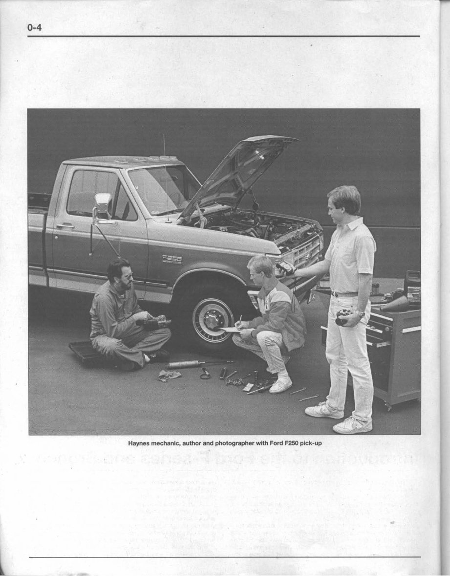
Haynes mechanic, author and photographer wHh Ford F250 pick-up
About this manual
0-5
Its purpose
The purpose of this manual is to help you get the best value from
your vehicle. It can do so in several ways. It can help you decide what
work must be done, even if you choose to have it done by a dealer ser-
vice department or a repair shop; It provides information and proce-
dures for routine maintenance and servicing; and it offers diagnostic
and repair procedures to follow when trouble occurs.
We hope you use the manual to tackle the work yourself. For
many simpler jobs, doing it yourself may be quicker than arranging an
appointment to get the vehicle into a shop and making the trips to
leave it and pick it up. More importantly, a lot of money can be saved
by avoiding the expense the shop must pass on to you to cover its la-
bor and overhead costs. An added benefit Is the sense of satisfaction
and accomplishment that you feel after doing the job yourself.
Using the manual
The manual Is divided into Chapters. Each Chapter is divided Into
numbered Sections, which are headed in bold type between horizontal
lines. Each Section consists of consecutively numbered paragraphs.
At the beginning of each numbered Section you will be referred to
any illustrations which apply to the procedures in that Section. The ref-
erence numbers used In Illustration captions pInpoint the pertinent
Section and the Step within that Section. That is, illustration 3.2 means
the Illustration refers to Section 3 and Step (or paragraph) 2 within that
Section.
Procedures, once described in the text, are not normally re-
peated. When it's necessary to refer to another Chapter, the reference
will be given as Chapter and Section number. Cross references given
without use of the word ·Chapter" apply to Sections and/or para-
graphs in the same Chapter. For example, ·see Section a" means in
the same Chapter.
References to the left or right side of the vehicle assume you are
Sitting in the driver's seat, facing forward.
Even though we have prepared this manual with extreme care,
neither the publisher nor the author can accept responsibility for any
errors in, or omissions from, the information given.
NOTE
A Note provides information necessary to properly complete a procedure or information which will make the procedure easier
to understand.
CAUTION
A Caution provides a special procedure or special steps which must be taken while completing the procedure where the Cau-
tion is found. Not heeding a Caution can result in damage to the assembly being worked on.
WARNING
A Warning provides a special procedure or special steps which must be taken while completing the procedure where the
Wamlng is found. Not heeding a Warning can result in personal injury.
Introduction to the Ford F-series and Bronco
The F-series and Bronco models are conventional front-engine,
rear-wheel drive vehicles.
Over the years of production covered by this manual, engine op-
tions include the 300 cu. in. (4.9L) inline six-cylinder engine, the 232
cu. In. V6 engine and the 255 cu. in., 302 cu. in. (5.0l), 351 cu. in.
ts.eu 400 and 460 (7.SL)va engines.
Power is transmitted through either manual or automatic trans-
mission to a driveshaft and solid rear aXle on two-wheel drive (2WD)
models. On four-wheel drive (4WD) models, a transfer case transfers
power to the front axle by way of a driveshaft. Transmissions used in-
clude a four-speed manual, two different five-speed overdrive manu-
als, a three-speed automatic and two different four-speed overdrive
automatics. Three different transfer cases are available - two manual
shift and one electronic shift.
All 2WD models use twin l-beam independent front suspension
with coil springs and radius arms. 4WD models (except F3S0) use a
similar independent front suspension with a two-piece front driveaxle
assembly, coil springs and radius arms (except F250). F250 4WD mod-
els use leaf springs instead of coil springs on its independent front sus-
pension. F350 4WD models use a solid front axle and leaf springs, All
models use semi-elliptlcalleaf springs at the rear.
All models are equipped with front disc and rear drum brakes.
---
0-6
J
r
Vehicle identification numbers
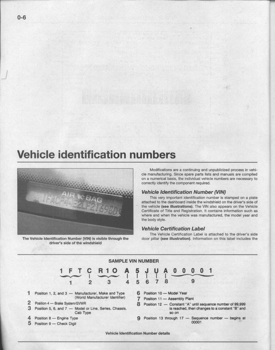
The Vehicle Identification Number (VIN) is visible through the
driver's side of the windshield
Modifications are a continuing and unpubllclzed process in vehi-
de manufacturing. Since spare parts lists and manuals are complied
on a numerical basis, ihe Individual vehicle numbers are necessary to
correctly identify the component required.
Vehicle Identification Number (VIN)
This very Important identification number is stamped on a plate
attached to the dashboard Inside the windshield on the driver's side of
, the vehicle (see illustrations). The VIN also appears on the Vehicle
Certificate of Title and Registration. It contains Information such as
where and when the vehicle was manufactured. the model year and
the body style.
Vehicle Certification Label
The Vehicle Certlf1cation Label Is attached to the driver's side
door pillar (see illustration), Information on this label includes the
SAMPLE VIN NUMBER
1 FTC
'--.,.,-' I
1 2
R10 A
'-.,.-' I
3 4
1 Position 1, 2, and 3- Manufacturer, Make and Type
(World Manufacturer Identifier)
2 Positlon.4- BrakeSystemtGVWR
3 Position 5, 6, and 7- Model or Line, Series, Chassis,
Cab Type
4 Position 8 - engine Type
5 Position 9 - Check Digit
5 J U A 0 0 0 0 1
I I I 1--------
5 6 7 8 9
6 Position 10 - Model Year
7 Position 11 - Assembly Plant
8 Position 12 - Constant "A" until sequence number of 99.999
is reached, then changes to Ii constant "S" and
so on
9 Position 13 through 17 - Sequence number - begins al
00001
Vehicle Identification Number details
Vehicle identification numbers
0-7
>--... DAll:: 2Ja3 GVWIl: IlOO ...,.,. KG
,,-_~FRONT GAWR: 3320L8 REAR~A.'WR~:~4004~~L8~:::====~:j-~~
'508KG WITH 18161<G ..:.
l--.LT 21MIeA ieo TIRES LT 216186R 180
,--_~1e)( 8K RIMS 18)( 8K
AT 51 PSI COLD AT 68 PSI COLD--------I~--('I
THIS VEHICLE CONFORMS TO ALL APPLICABLE FEDERAL MOTOR VEHICLE SAFETY
STANDARDS IN EFfECT ON THE DATE OF MANUFACTURE SHOWN ABOVE
YIN: 1f"I'EJI2IHIPLA
TYPE: TRUCK 7~~
w (t, (~ eJ) ~, lFl (GI (HI
II111111111111 111I
!---t-~
050
...,. BY FORD MOTOR CO. IN U.s.A.
7N 1M
SPRING
2 D 2 8
WeB)eC)(D)
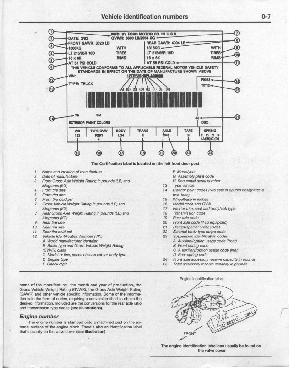
The Certification label is located on the left front door post
1 Name and location of manufacture
2 Date of manufacture
3 Front Gross Axle Weight Rating in pounds (LB) and
kilograms (KG)
4 Front tire size
5 Front rim size
6 Front tire cold psi
7 Gross Vehicle Weight Rating in pounds (LB) and
kilograms (KG)
8 Rear Gross Axle WeIght Rating in pounds (LB) and
kilograms (KG)
9 Rear tire siZe
10 Rear rim size
11 Rear tire cold psi
12 Vehicle Identification Number (VIN)
A World manufacturer Identifier
B Brake type and Gross Vehicle Weight Rating
(GVWR) class
C Model or line, series chassis cab or body type
D Engine type
E Check digit .
F Modelyear
G Assembly plant code
H Sequential serial number
13 Type vehicle
14 Exterior paint codes (two sets of figures designates a
two-tone)
15 Wheelbase in inches
16 Model code and GVW
17 Interior trim, seat and body/cab type
18 Transmission code
19 Rear axle code
20 Front axle code (If so equipped)
21 District/special order codes
22 External body type stripe code
23 Suspension identification codes
A Auxiliary/option usage code (front)
B Front spring code
CA auxiliary/optIon usage code (rear)
D Rear spring code
24 Front axle accessory reserve capacHy in pounds
25 Total accessory reserve capacHy in pounds
Engine Identification label
name ot the manufacturer, the month and year of production, the
Gross Vehicle Weight Rating (GVWR), the Gross Axle Weight Rating
(GAWR) and other vehicle specific Information. Some of the informa-
tion Is in the form of codes, requiring a conversion chart to obtain the
desired Information. Included are the conversions forthe rear axle ratio
and transmission type codes (see Illustrations).
Engine number
The engine number is stamped onto a machined pad on the ex-
ternal surface of the engine block. There's also an identification label
that's usuaJly on the valve cover (see illustration).
The engine identification label can usually be found on
the valve cover
0-8
Buying parts
Replacement parts are available from many sources, which gen-
erally fall Into one of two categories - authorized dealer parts depart-
ments and independent retail auto parts stores. Our advice conceming
these parts is as follows:
Retail auto parts stores: Good auto parts stores will stock fre-
quently needed components which wear out relatively fast, such as
clutch components, exhaust systems, brake parts, tune-up parts, etc.
These stores often supply new or reconditioned parts on an exchange
basis, which can save a considerable amount of money. Discount auto
parts stores are often very good places to buy materials and parts
needed for general vehicle maintenance such as oil, grease, filters,
spark plugs, belts, touch-up paint, bulbs, etc. They also usually sell
tools and general accessories, have convenient hours, charge lower
prices and can often be found not far from home.
Authorized dealer parts department: This is the best source for
parts which are unique to the vehicle and not generally available
elsewhere (such as major engine parts, transmission parts, trim
pieces, etc.).
Warranty intormstion: If the vehicle is still covered under war-
ranty, be sure that any replacement parts purchased - regardless of
the source - do not invalidate the warranty!
To be sure of obtaining the correct parts, have engine and chassis
numbers available and, if possible, take the old parts along for positive
Identification.
used once. If they are removed, they lose their locking ability and must
be replaced with new ones.
Rusted nuts and bolts should be treated with a penetrating fluid
to ease removal and prevent breakage. Some mechanics use turpen-
tine In a spout-type oil can, which works quite well. After applying the
rust penetrant, let it work for a few minutes before trying to loosen the
nut or bolt. Badly rusted fasteners may have to be chiseled or sawed
off or removed with a special nut breaker, available at tool stores.
If a bolt or stud breaks off in an assembly, it can be drilled and re-
moved with a special tool commonly available for this purpose. Most
automotive machine shops can perform this task, as well as other re-
pair procedures, such as the repair of threaded holes that have been
stripped out.
Flat washers and lockwashers, when removed from an assembly,
should always be replaced exactly as removed. Replace any damaged
washers with new ones. Never use a lockwasher on any soft metal sur-
face (such as aluminum), thin sheet metal or plastlc,
Maintenance techniques,
tools and working facilities
Maintenance techniques
There are a number of techniques Involved In maintenance and
repair that wlll'be referred to throughout this manual. Application of
these techniques will enable the home mechanic to be more efficient,
better organized and capable of performing the various tasks properly,
which will ensure that the repair job is thorough and complete.
Fasteners
Fasteners are nuts, bolts, studs and screws used to hold two or
more parts together. There are a few things to keep in mind when
working with fasteners. Almost all of them use a locking device of
some type, either a lockwasher, locknut, locklng tab or thread adhe-
sive. All threaded fasteners should be clean and straight, with undam-
aged threads and undamaged corners on the hex head where the
wrench fits. Develop the habit of replacing all damaged nuts and bolts
with new ones. Special locknuts with nylon or fiber Inserts can only be
Maintenance techniques, tools and working facilities 0-9
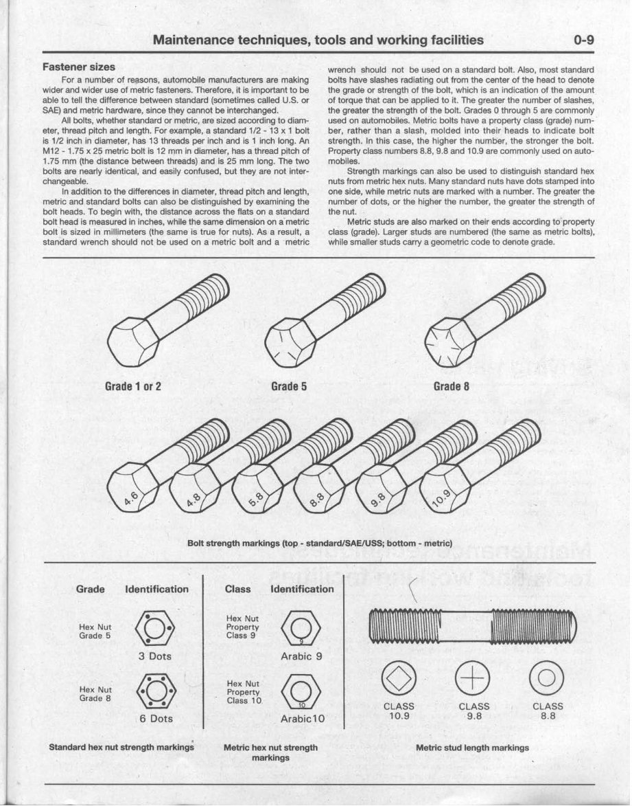
Fastener sizes
For a number of reasons, automobile manufacturers are making
wider and wider use of metric fasteners. Therefore, it is important to be
able to tell the difference between standard (sometimes called U.S. or
SAE) and metric hardware, since they cannot be interchanged.
All bolts, Whether standard or metric, are sized according to diam-
eter, thread pitch and length. For example, a standard 1/2 - 13 x 1 bolt
is 112 inch in diameter, has 13 threads per inch and is 1 Inch long. An
M12 - 1.75 x 25 metric bolt Is 12 mm In diameter, has a thread pitch of
1.75 mm (the distance between threads) and is 25 mm long. The two
bolts are nearly identical, and easily confused, but they are not Inter-
changeable.
In addition to the differences 1n diameter, thread pitch and length,
metric and standard bolts can also be distinguished by examining the
bolt heads. To begin with, the distance across the flats on a standard
bolt head Is measured in Inches, while the same dimension on a' metric
bolt Is sized in millimeters (the same is true for nuts). As a result, a
standard wrench should not be used on a metric bolt and a metric
wrench should not be used on a standard bolt. Also, most standard
bolts have slashes radiating out from the center of the head to denote
the grade or strength of the bolt, which is an indication of the amount
of torque that can be applied to It. The greater the number of slashes,
the greater the strength of the bolt. Grades 0 through 5 are commonly
used on a'Utomobiles. Metric bolts have a property class (grade) num-
ber, rather than a slash, molded into their heads to indicate bolt
strength. In this case, the higher the number, the stronger the bolt.
Property class numbers 8.8, 9,8 and 10.9 are commonly used on auto-
mobiles.
Strength markings can also be used to distinguish standard hex
nuts from metric hex nuts. Many standard nuts have dots stamped into
one side, while metric nuts are marked with a number. The greater the
number of dots, or the higher the number, the greater the strength of
the nut.
Metric studs are also marked on their ends according to property
class (grade). Larger studs are numbered (the same as metric bolts),
while smaller studs carry a geometriC code to denote grade.
Grade 1 or 2 Grade 5 Grade 8
Bolt strength markings (top· standard/SAElUSS; bottom - metric)
Grade Identification Class Identification
\
@
Hex Nut
@
--
--
Hex Nut Property
Grade 5
Class 9
3 Dots Arabic 9
Hex Nut
@
Hex Nut
@
©
c±) @
Property
Grade 8
Class 10
•
CLASS
CLASS
CLASS
6 Dots Arabic 10
10.9
9.B
B.B
.
Standard hex nut strength markings
Metric hex nut strength MetriG stud length markings
markings
0-10 Maintenance techniques, tools and working facilities
It should be noted that many fasteners, especially Grades 0
through 2, have no distinguishing marks on them. When such is the
case, the only way to determine whether it Is standard or metric is to
measure the thread pitch or compare it to a known fastener of the
same size.1993
Standard fasteners are often referred to as SAE, as opposed to
metric. However, it should be noted that SAE technically refers to a
non-metric fine thread fastener only. Coarse thread non-metric fasten-
ers are referred to as USS sizes.
Since fasteners of the same size (both standard and metric) may
have different strength ratings, be sure to reinstall any bolts, studs or
nuts removed from your vehicle in their original locations. Also, when
replacing a fastener with a new one, make sure that the new one has a
strength rating equal to or greater than the original.
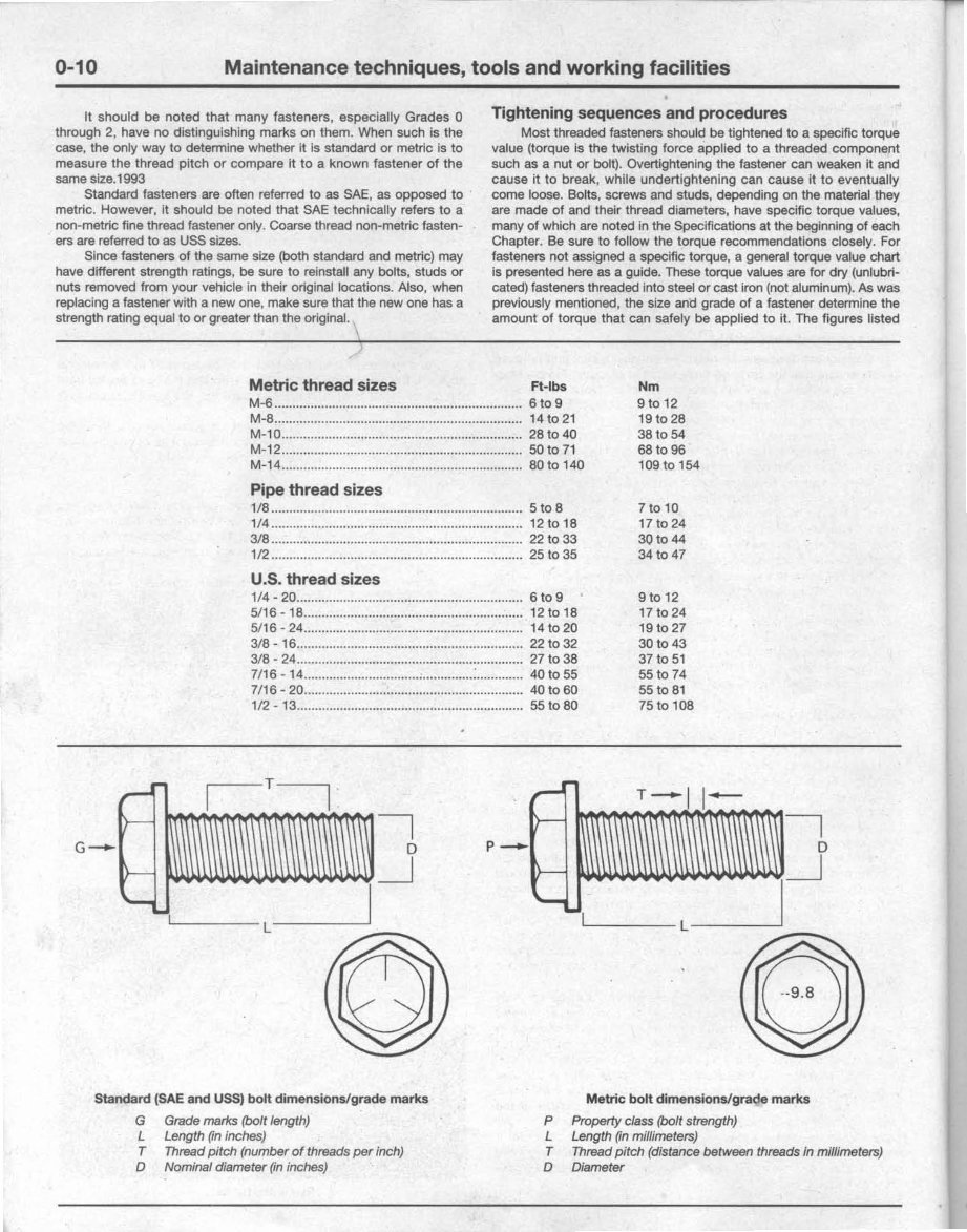
Tightening sequences and procedures
Most threaded fasteners should be tightened to a specific torque
value (torque Is the twisting force applied to a threaded component
such as a nut or bolt). Overtightening the fastener can weaken it and
cause i1 to break, while undertightening can cause It to eventually
come loose. Bolts, screws and studs, depending on the material they
are made of and their thread diameters, have specific torque values,
many of which are noted in the Specifications at the beginning of each
Chapter. Be sure to follow the torque recommendations closely. For
fasteners not assigned a specific torque, a general torque value chart
is presented here as a guide. These torque values are for dry (unlubrl-
cated) fasteners threaded into steel or cast iron (not aluminum). As was
previously mentioned, the size and grade of a fastener determine the
amount of torque that can safely be applied to it. The figures listed
Metric thread sizes Ft-Ibs
M-6 6109
M-8 141021
M-10 28 to 40
M-12 SOt071
M-14 80 to 140
Pipe thread sizes
1/8 5108
1/4 121018
3/8 22 to 33
1/2 25 to 35
U.S. thread sizes
1/4 - 20 6 to 9
5/16 -18 12 to 18
5116 - 24 14 to 20
3/8 - 16 221032
3/8 - 24............................................................... 27 to 38
7/16 -14 : 40 to 55
7/16 - 20 40 to 60
112 - 13 55 to 80
Nm
9 to 12
19 to 28
38 to 54
68 to 96
109 to 154
7to 10
17 to 24
30 to 44
34 to 47
9 to 12
17 10 24
19 to 27
301043
37 to 51
55 to 74
55 to 81
75 to 108
T
G-
~I""
I I'
}-
il II
1\
'L\
\\\
~\I\
~
t .\ It tl 1.1
~ ..
I
L
Standard (SAE and USS) bolt dimensions/grade marks
G Grade marks (bolt length)
L Length (in inches)
T Thread pitch (number of threads per inch)
o Nominal diameter (in inches)
~ ...
T--II~
....
)-
l\
.1 I I l\'\
l\ 1\
~
~ .1 1 til I\I~
'--''''I
L~
p_.
Metric bolt dimensions/grade marks
P Property class (bolt strength)
L Length (in millimeters)
T Thread pitch (distance between threads in millimeters)
o ~iameter
You're Reading a Preview
What's Included?
Fast Download Speeds
Online & Offline Access
Access PDF Contents & Bookmarks
Full Search Facility
Print one or all pages of your manual
$35.99
Viewed 58 Times Today


Secure transaction
What's Included?
Fast Download Speeds
Online & Offline Access
Access PDF Contents & Bookmarks
Full Search Facility
Print one or all pages of your manual
$35.99
Get your hands on the complete service and repair manual for the 1983-1987 Ford Bronco II. This comprehensive manual is an invaluable resource for professional mechanics and DIY enthusiasts alike.
- Save money by performing your own repairs with easy-to-follow, step-by-step instructions and detailed pictures covering all areas of servicing and repairs.
- Once ed, the manual is yours to keep forever. Print out specific pages, chapters, or the entire manual, and even it to your tablet for easy access.
Models covered include all variations of engines, trims, and transmission types.
- High-quality service repair workshop manual that covers all repair procedures from A to Z.
- Compatible with all PC and MAC computers, tablets, and mobile phones. The only software required is Adobe Reader, which can be ed for free.
Upon payment via Visa, MasterCard, or PayPal, the manual will be instantly emailed to the address used during checkout, ensuring a prompt delivery. Customer satisfaction guaranteed.


