Albea Electrical system 1370 8v Index 55. Copyright by Fiat Auto page Position of vehicle components CONTROL UNITS POSITION ON VEHICLE 1 Braching unit DASHBOARD CONTROL UNIT AND BODY COMPUTER DETACHMENT - REATTACHMENT 2 ENGINE COMPARTMENT CONTROL UNIT DETACHMENT – REATTACHMENT 4 ENGINE COMPARTMENT CONTROL UNIT CANISTER DETACHMENT - REATTACHMENT 4 Instrument panel INSTRUMENT PANEL DETACHMENT – REATTACHMENT 5 INSTRUMENT PANEL REMOVAL – REFITTING 6 Miscellaneus devices EMOVAL - REFITTING CONTACT BLOCK OF IGNITION SWITCH 7 FIAT CODE ANTENNA DETACHMENT –REATTACHMENT 8 REMOVAL - REFITTING POWER WINDOW CONTROL UNIT 8 STEERING WHEEL STALK DETACHMENT – REATTACHMENT 9 REMOVAL - REFITTING HORN CONTROL 10 REMOVAL - REFITTING CENTRAL SWITCH ASSEMBLY ON DASHBOARD 10 REMOVAL - REFITTING SWITCH ASSEMBLY ON DASHBOARD, DRIVER'S SIDE 10 REMOVAL - REFITTING FRONT POWER SOCKET 11 REMOVAL - REFITTING RADIO 12 Air bag DRIVER’S AIRBAG DETACHMENT – REATTACHMENT 13 CLOCK WIRE REMOVAL – REFITTING 14 PASSENGER’S AIRBAG DETACHMENT – REATTACHMENT 15 REMOVAL - REFITTING SUPPORT FOR AIR BAG, PASSENGER SIDE 16 PASSENGER’S AIRBAG DEACTIVATION SWITCH DETACHMENT – REATTACHMENT 16 page Lighting REMOVAL - REFITTING FRONT LIGHT CLUSTER 17 HEADLIGHT POSITIONING 19 Starting and charging REMOVAL – REFITTING BATTERY 20 ALTERNATOR REMOVAL - REFITTING - 1.4 8V engine 21 STARTER REMOVAL - REFITTING - 1.4 8V engine 22 Compressor COMPRESSOR REMOVAL - REFITTING - 1.4 8V engine 23 Self-learning procedures THROTTLE BODY ACTUATOR SELF LEARNING 24 CLIMATE CONTROL SYSTEM SELF LEARNING 24
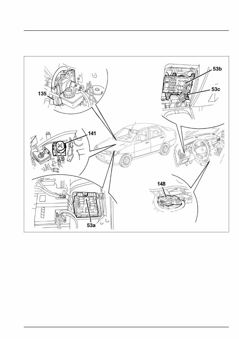
Albea Electrical system 1370 8v Position of vehicle components 55. Copyright by Fiat Auto 1 CONTROL UNITS POSITION ON VEHICLE 78SER277C 53a Engine compartment shunting control unit 53b Shunting control unit under the dashboard 53c Body Computer 135 Injection / ignition control unit 141 ABS control unit 148 Air Bag control unit
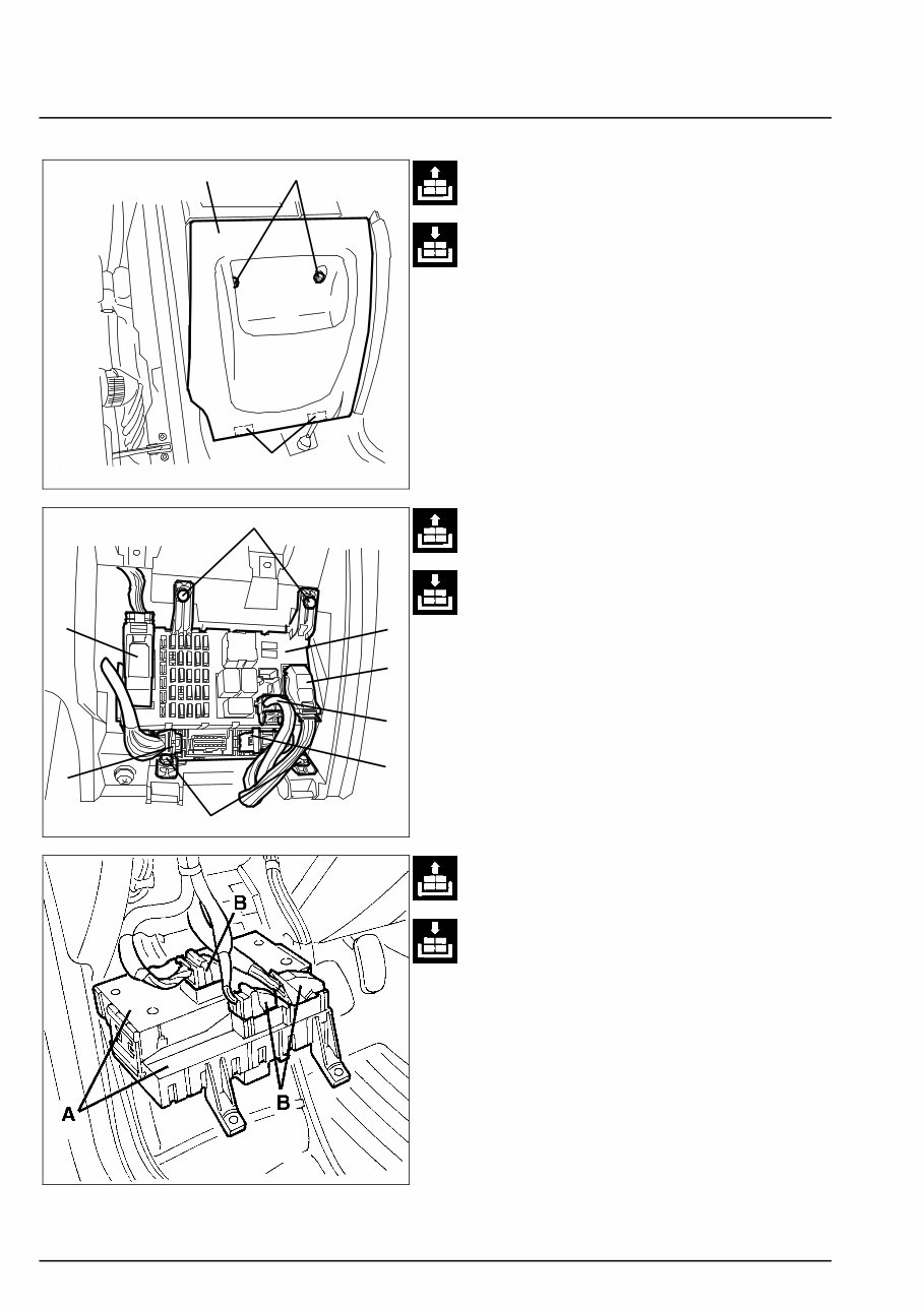
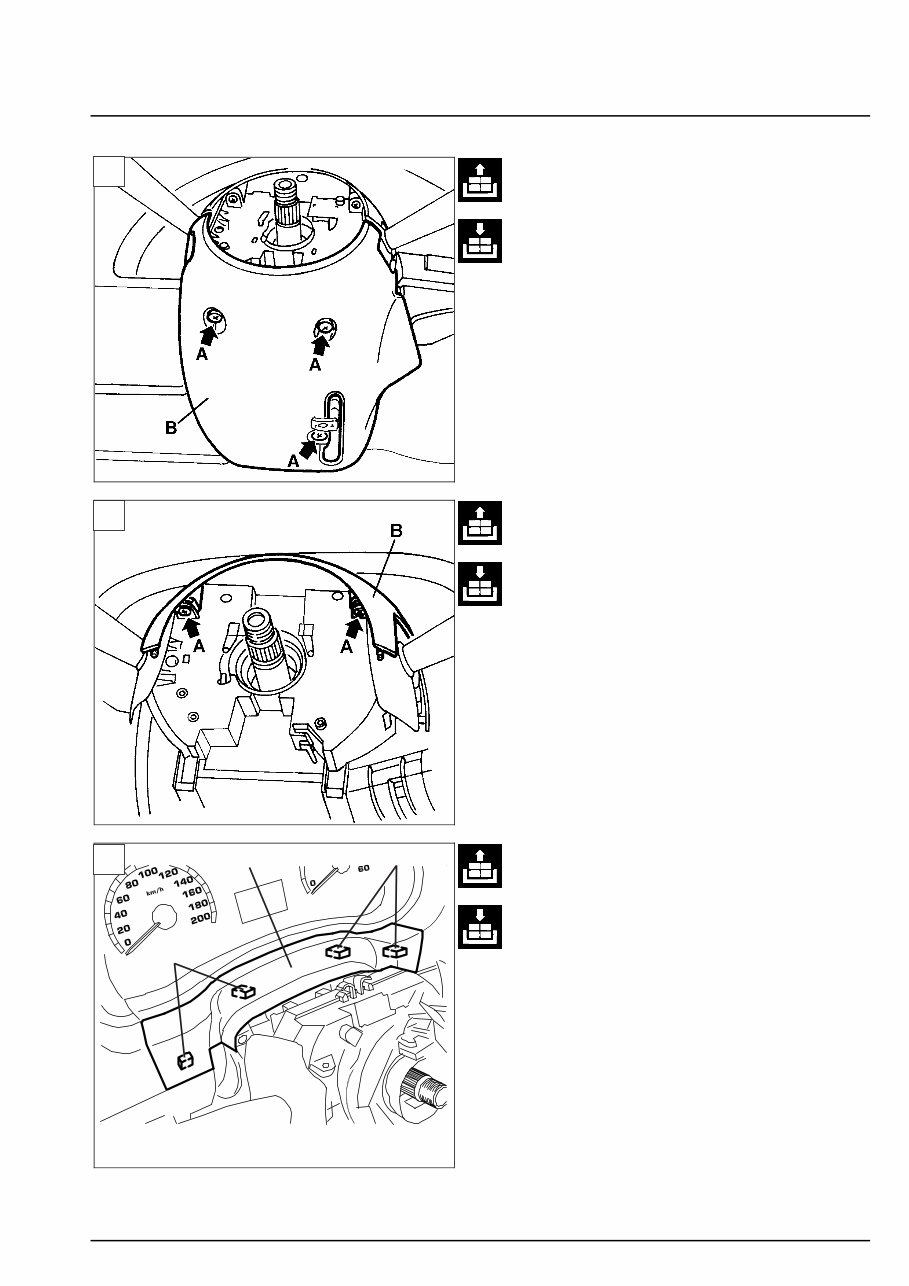
Electrical system Albea Branching unit 1370 8v 55. 2 C B A 78SER360 A A C C B A A A DASHBOARD CONTROL UNIT AND BODY COMPUTER DETACHMENT - REATTACHMENT - Unscrew the fastening screws (A). – Lower the door (B) providing access to the shunting con- trol unit and the body computer. - Remove the door (B) by releasing it from the retaining elements (C). - Disconnect the electric connections (A). of control unit (B) - Unscrew the control unit and body computer fastening screws (C). 78SER361 - Slightly move aside the control unit with the body computer (A) and disconnect the connec- tions (B). - Recover the control unit with the body com- puter. 4o024LL01
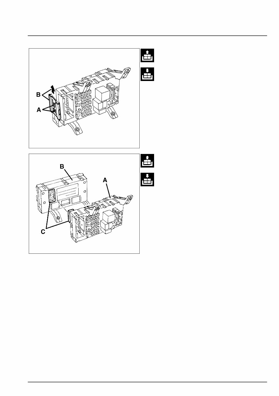
Albea Electrical system 1370 8v Branching unit 55. Copyright by Fiat Auto 3 4o024LL02 - Release the retaining elements (A) and take the fastening plate (B) out of both sides of the control unit. - Separate the shunting control unit (A) from the body computer (B) by releasing the electric connection (C). NOTE Refit by reversing the removal sequence. NOTE After the intervention, check for system op- eration by means of an EXAMINER or other diagnostic instruments. 4o024LL03
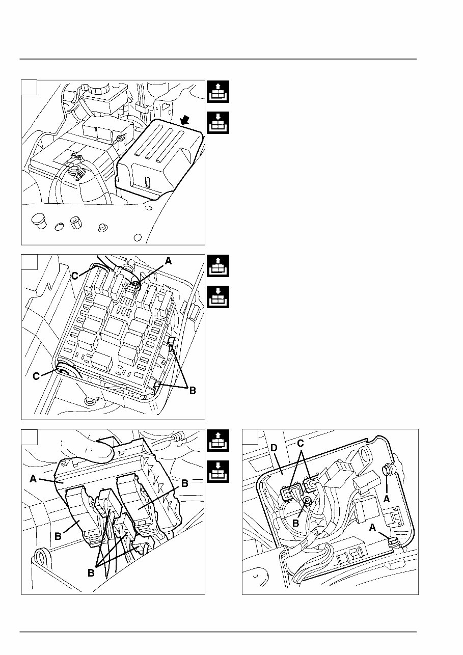
Electrical system Albea Branching unit 1370 8v 55. 4 78SER219 ENGINE COMPARTMENT CONTROL UNIT DETACHMENT - REATTACHMENT - Open the bonnet. 1. Take off the engine compartment control unit cover. 2. Disconnect the electric connection (A). Re- lease the retaining element (B) then the pins from their respective seats (C). 3. Move aside the engine compartment control unit (A) and disconnect the electric connec- tions (B). Recover the engine compartment control unit (A). ENGINE COMPARTMENT CONTROL UNIT CANISTER DETACHMENT - REATTACH- MENT - Remove the engine compartment control unit (see previous procedure). 4. Unscrew the screws (A) and the nut (B) fas- tening the canister. Take off the electric con- nections (C) from the retaining elements and remove canister (D). NOTE Refit by reversing the removal se- quence.Refit by reversing the removal se- quence. 78SER220 78SER221 78SER222 1 2 3 4
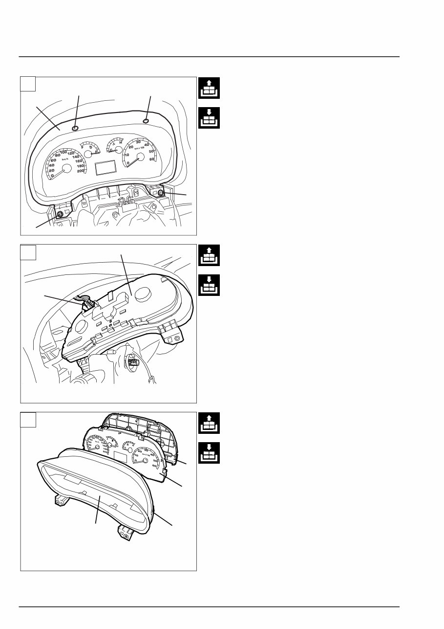
Albea Electrical system 1370 8v Instrument panel 55. Copyright by Fiat Auto 5 78SER362 INSTRUMENT PANEL DETACHMENT - REATTACHMENT - Remove the driver’s side airbag (see the rele- vant paragraph). - Remove the steering-wheel (see Section 41). 1. Unscrew the three screws (A) shown and re- move the steering column lower guard (B). 2. Unscrew the two screws (A) shown and re- move the steering column upper guard (B). 78SER363 B A B 3. Remove the guard (A) by releasing it from the retaining elements (B). 78SER364 1 2 3
Electrical system Albea Instrument panel 1370 8v 55. 6 B A A A A 78SER365 B A 1. Unscrew the screws (A) then remove the con- trol board (B) 2. Slightly move aside the control board (B) and disconnect the electric connections (A). NOTE Refit by reversing the removal sequence. 78SER366 B A D C INSTRUMENT PANEL REMOVAL - RE- FITTING - Remove the instrument panel (see the rele- vant paragraph). 3. Release the internal retaining elements (A). Separate (the control board frame (B) and rear cover (C). Recover the control board (D) . NOTE Refit by reversing the removal sequence. 78SER367 1 2 3
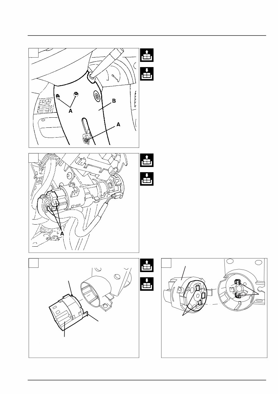
Albea Electrical system 1370 8v Miscellaneous devices 55. Copyright by Fiat Auto 7 3 4 78SER350 REMOVAL - REFITTING CONTACT BLOCK OF IGNITION SWITCH 1. Unscrew the screws (A) and remove the lower guard (B) of the steering column. 2. Disconnect the electrical connections (A) of the ignition switch. 3. Extract the contact block (A) freeing the fas- teners (B) from the related seats. NOTE For refitting, carry out the steps per- formed for removal in reverse order, with the following warning. 4. When inserting the contact block (A) couple the projections (B) with the related seats (C). 78SER351 A B C 78SER352 78SER353 1 2 A B B
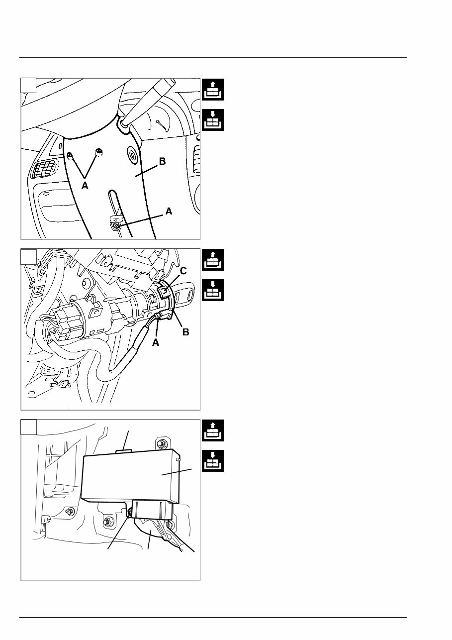
Electrical system Albea Miscellaneus devices 1370 8v 55. 8 78SER162 FIAT CODE ANTENNA DETACHMENT - REATTACHMENT 1. Unscrew the screws (A) and remove the steer- ing column lower guard (B). 2. Disconnect connector (A) and remove the Fiat CODE antenna (B) by releasing the retaining elements (C). NOTE Refit by reversing the removal sequence 78SER182 D B C A REMOVAL - REFITTING POWER WIN- DOW CONTROL UNIT 3. Working under the dashboard covering, pas- senger side, disconnect the electrical connec- tion (A) of the power window control unit (B). - Unscrew the screw (C). - Remove the control unit (B) freeing the fas- tener (D). NOTE For refitting, carry out the steps per- formed for removal in reverse order. 78SER367 1 2 3
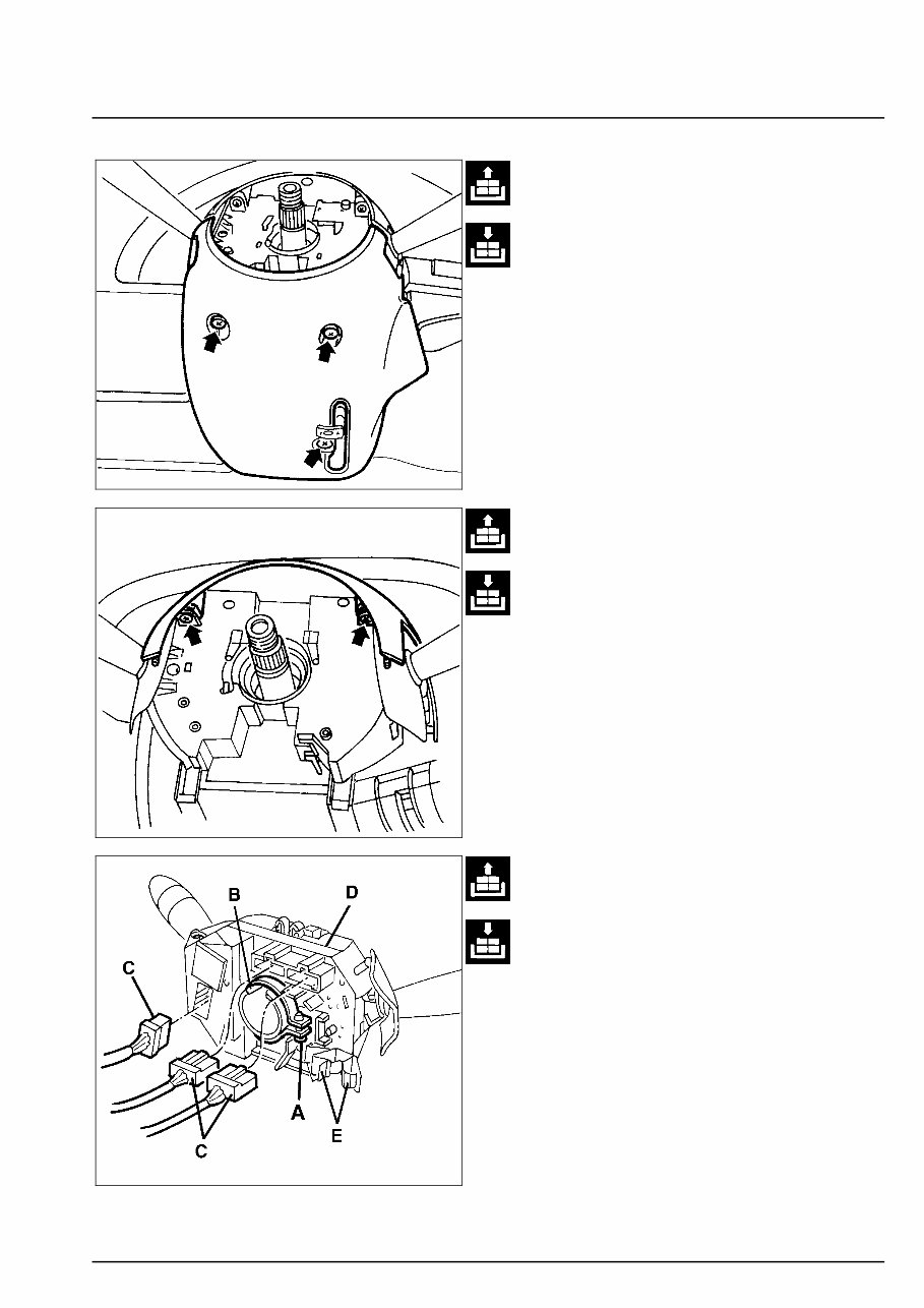
Albea Electrical system 1370 8v Miscellaneous devices 55. Copyright by Fiat Auto 9 78SER368 STEERING WHEEL STALK DETACH- MENT - REATTACHMENT - Remove the driver’s side airbag (see the rele- vant paragraph). - Remove the steering-wheel (see Section 41). - Remove the spiralled cable (see the relevant paragraph). - Unscrew the three screws shown and remove the steering column lower guard. - Unscrew the two screws shown and remove the steering column upper guard. 4o053LL02 - Loosen the steering column stalk fastening strap (A). - Move the stalk (D) slightly aside, releasing the tongue (B) from steering column retaining elements. - Disconnect the three electric connections (C) - Release the electric cables from the retaining elements (E), than remove the steering col- umn stalk unit (D). NOTE Refit by reversing the removal sequence. 78SER369
Get your hands on the 2006 FIAT ALBEA Service and Repair Manual, a comprehensive guide for fixing vehicle issues. Whether you're a professional mechanic or a DIY enthusiast, these manuals provide detailed instructions and procedures to help you tackle car problems with ease.
These manuals are invaluable for immediate car repairs, offering technical data, diagrams, and a complete list of car parts with illustrations and pictures. They cover various sections including maintenance, engine, control system, mechanical, fuel service specifications, and much more.
Available in both .PDF and .OVA file formats, these manuals are compatible with Windows Vista32 and 64, XP, ME, 98, NT, 2000, and Mac. They come with complete instructions, wiring schematics, and diagrams to facilitate vehicle servicing and repairs.
With the ability to print only the necessary pages and diagrams, these manuals are convenient and user-friendly. They allow you to save time and money by enabling you to perform simple car repairs on your own, without relying solely on a mechanic.
Equip yourself with the knowledge and resources to maintain and repair your vehicle effectively. These manuals are designed to keep your car in top condition, ensuring its durability and performance over time.
Complete step-by-step instructions
Diagrams and illustrations
Wiring schematics and specifications
Windows and Mac compatibility
Comprehensive coverage of various car systems
Take advantage of these manuals to enhance your car repair skills and keep your vehicle in optimal condition for years to come.