FIAT 500 1957-73 Workshop Manual Autobooks Models Covered Fiat New 500 Fiat 500D Fiat 500F Fiat 500L Fiat and Autobianchi Giardiniera
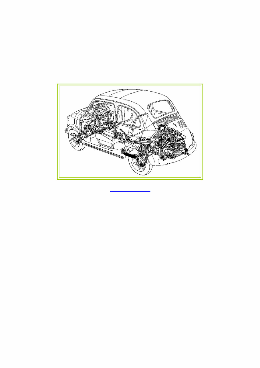
CHAPTER 1 THE ENGINE 1 :1 1 :2 1 :3 1 :4 1 :5 1 :6 1 :7 1 :8 1:9 1 :10 1 :11 Description Engine removal (sedan—all versions) Engine removal (station wagon) Engine disassembly (sedan—all versions) Engine disassembly (station wagon) Cylinder head removal, servicing and replacement Timing gear overhaul Crankcase and cylinders Piston assembly Connecting rods Crankshaft and main bearings 1 :1 Description The 'New 500' two-cylinder aircooled engine operates on the four-stroke 'Otto Cycle' and is fitted directly to the transmission unit which incorporates the rear drive assembly as shown in FIG 1 :1 and FIG 1 :2. With the power unit fitted at the rear several advantages are obtained including better load distribution to the wheels when the vehicle is loaded, elimination of propeller shaft reducing the size of centre tunnel and better use of available space. The cylinder block comprises two cast iron cylinder barrels with cooling fins. The bottom of the cylinders fit into machined seats in the aluminium crankcase. The aluminium crankcase carries eight studs on which are located the two cylinder barrels with the aluminium cylinder head on the top. A two bush crankshaft of special cast iron is fitted into the lower half of the crankcase. The crankshaft is F500 9 provided with a counterweight and is hollow to allow for lubrication. The steel connecting rods have thin wall bearing halves on the big-end, and bronze bushes in the small-end. The offset piston pin is of steel and retained in the piston by two circlips. Light alloy pistons are used and are of the taper-oval- shaped type with a maximum diameter at the base of the skirt, along an axis perpendicular to the piston pin. Pistons are fitted with four rings as follows, one compression at the top, two standard oil scraper rings and one side slotted oil scraper ring. The one-piece aluminium cylinder head is finned to provide a larger cooling surface and carries the inlet and exhaust manifolds. The inlet passages merge into a single centralized flange onto which is mounted the carburetter. The exhaust passages run almost parallel to the axis of the engine. 1 :12 1 :13 1 :14 1 :15 1 :16 1 :17 1 :18 1 :19 1 :20 1 :21 1 :22 Flywheel and starter ring gear The oil pump Lubrication, oil filter, relief valve Valve timing Valve stem to rocker clearance Engine assembly (sedan—all versions) Engine assembly (station wagon) Power plant mounting Adjustment of generator and fan belt drive Modifications Fault diagnosis
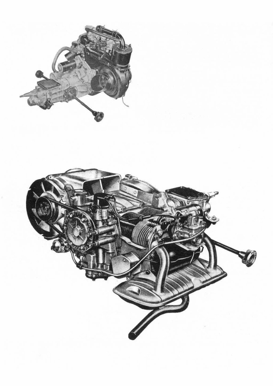
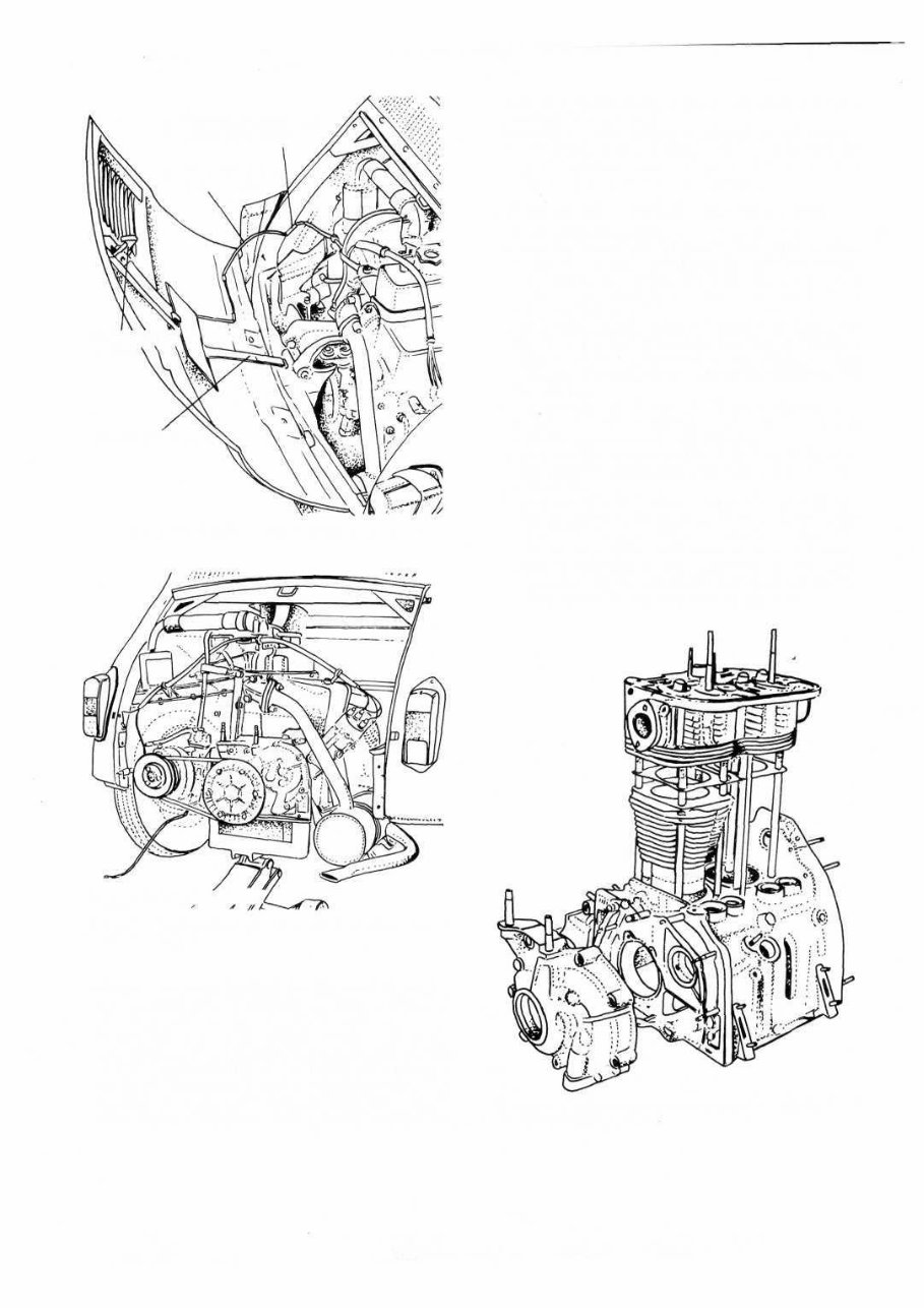
FIG 1:1 Left side view of the power plant to suit 500 Sedan 10 FIG 1:2 Right side rear three-quarter view of the power plant for 500 Station Wagon Mounted on the top of the cylinder head is the overhead valve rocker mechanism that is operated by a chain driven camshaft through tappets and vertical pushrods. The carburetter is of the downdraft type fitted with a starting device that is controlled by a lever on the central floor tunnel. A pleated paper element air cleaner and silencer is fitted to the carburetter air intake. A mechanical diaphragm type fuel pump operated from the camshaft by a pushrod, supplies petrol to the carburetter from a fuel tank located at the front of the vehicle. Engine lubrication is provided by a gear pump driven from the camshaft and mounted within the timing cover drawing oil from the engine sump. The oil is cleaned by a centrifugal filter situated at the rear end of the crankshaft and pressure is controlled by a valve mounted on the pump body. Crankcase ventilation is provided for through a rubber hose connected to the top of the rocker cover. The engine is cooled by air from a centrifugal blower mounted on the generator shaft and housed in a specially designed cowling conveying air to and around the engine. The air temperature is governed by a special thermostat fitted in the engine cowling.
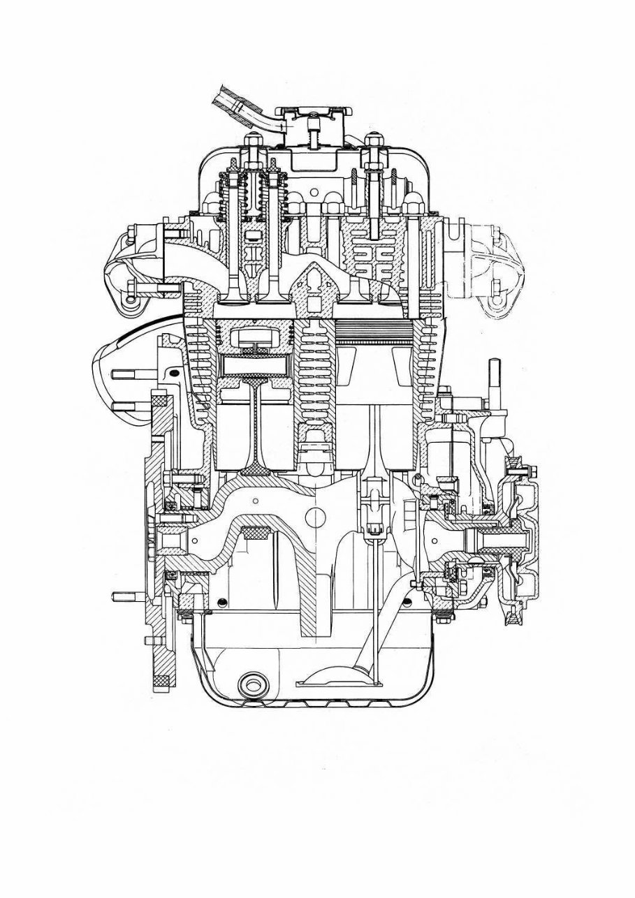
FIG 1:3 Engine section through crankshaft, pistons and valves F500 11
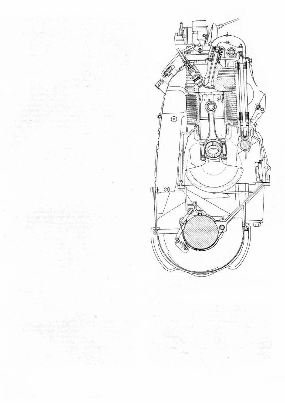
FIG 1:4 Engine cross-section through a cylinder 12
The interior of the car can be heated by the engine warmed air being ducted into the front compartment and controlled by a lever on the heating system tunnel. Engine ignition is by a battery, ignition coil and distribu- tor which is driven by a gear on the camshaft. The engine is started by an electric starter motor which is mounted on the gearbox casing and is controlled by a lever located behind the gearchange lever. The complete power unit is mounted by a spring support at the centre of the rear body crossmember and by two rubber pads mounted laterally to the gearbox. 1 :2 Engine removal (sedan—all versions) To remove the engine from the car proceed as follows: Raise the rear of the car and place on firmly based stands placed under suitable brackets on the underside of the body. Disconnect the battery positive terminal clamp from the battery terminal post. Release the clip securing the main petrol pipe to the tank sender unit and ease the pipe from the unit. Drain the oil from the engine sump into a suitably sized container. Disconnect the rear number plate light wire (see FIG 1 :6 ). Release the engine compartment lid check strap from its slot and separate the lid from the body by sliding the hinge apart. Remove the cables attached to the ignition coil, also to the generator and the starter motor. Remove the starter motor control tie rod. Release the oil pressure indicator cable, the main petrol pipeline at the pump, the accelerator and starting device controls. Remove the two hoses of the heating and cooling system which are the input hose to the blower and the hose for the car heating system. Release and lift out the engine apron. Remove the starter motor mounting bolts and carefully lift away the motor. Using a garage hydraulic jack with suitable cradle (see FIG 1:7 ) or a rope sling relieve the engine weight from its mountings. Remove the nuts securing the gearbox to the engine and the flywheel protection apron. Remove the bolts fixing the elastic support to the cross- member. Remove the rear crossmember mounting nuts noting that the engine earth cable is held by one mounting nut and lift away the crossmember. Carefully ease the engine away from the gearbox ensuring that there is no strain placed on the clutch shaft. Lower the engine to the floor taking care that no weight is allowed on any of the attachments. 1 2 3 4 5 6 7 8 1 :3 Engine removal (station wagon) To remove the engine from the station wagon proceed as follows: 1 Raise the rear of the vehicle and place on firmly based stands placed under suitable brackets on the underside of the body. 2 Disconnect the battery positive terminal clamp from the battery terminal post. Release the clip securing the main petrol pipe to the tank sender unit and ease the pipe from the unit. Drain the oil from the engine sump into a clean dry container of suitable size. 3 Hold the rear door open and secure using string to stop it swinging to the closed position. Secure the luggage compartment floor panel in its upright position. F500 13 4 Remove the cables attached to the ignition coil, also to the generator and starter motor. Remove the starter motor control tie rod. Release the oil pressure indicator cable, the main petrol pipeline at the pump, the accele- rator and starting device controls. Disconnect the air filter housing. 5 Remove the hose connecting the car heating system to the engine cowling. Disconnect the clip holding the air pipe to the blower and carefully disconnect the pipe from the blower cowling. Remove the starter motor mounting bolts and carefully lift away the motor. FIG 1:5 120.000 engine assembly: cross-section view through a cylinder
LID CHECK ARM FIG 1:6 Engine compartment lid open LID LOCKING HOOK NUMBER PLATE LAMP CABLE NUMBER PLATE LAMP CABLE JUNCTION CROSS MEMBER ARR.2O74. FIG 1 :7 Engine removal using the jack with cross- member Arr.2074 6 Using a garage hydraulic jack with a suitable cradle relieve the engine weight from its mountings. Remove the nuts securing the gearbox to the engine. 7 Remove the nuts securing the rear bumper blade and panel to the body. Note that the engine earth cable is held by one mounting nut. Carefully dismantle the engine elastic mounting or release the bracket from the engine rear cover by removing the two nuts and washers. Lift away the rear panel assembly carefully making sure 14 FIG 1:8 Engine components: crankcase, cylinder head, timing sprockets cover To dismantle the engine proceed as follows: 1 Remove the exhaust silencer by releasing the two collars for attachment to the engine and the two con- nections for the exhaust pipe. It will be noted that there is one exhaust pipe connection on either side of the cylinder head. 2 Place the engine on a firm wooden top bench. Remove the two tappet cover retaining nuts and washers and lift away the cover. Remove the connection for cooling air delivery to the sump cooling ducts at the side of the sump. 3 Remove the air cleaner after first releasing the two bolts on the air cowling and the two nuts for the air elbow connection to the carburetter. 4 Remove the generator drive belt by releasing the three nuts so splitting the semi-pulley. Lift away the drive belt. 5 Remove all the bolts securing the air conveyor ducting to the cylinder head, to the crankcase and also to the engine cowling assembly opposite to the air conveyor. Release the accelerator control tie rod and carefully lift away the air conveyor assembly complete with the generator after first removing the clamp fixing the generator to the crankcase. 1 :4 Engine disassembly (sedan—all versions) that rear air ducting panels are not strained or the mating faces damaged. 8 Carefully ease the engine away from the gearbox ensur- ing that there is no strain placed on the clutch shaft. Lower the engine to the floor taking care that no weight is allowed on any of the attachments.
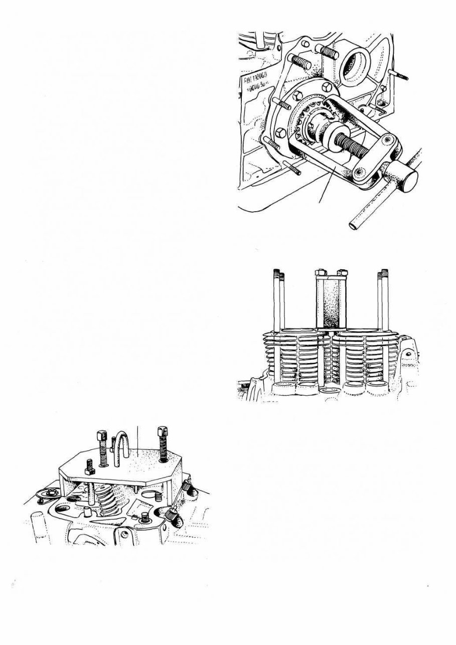
6 Release the ignition distributor support retaining nut and lift away the distributor together with its support. 7 Remove all the mounting bolts of the engine cooling cowling and lift away the assembly. Release the two carburetter retaining nuts and carefully remove the carburetter together with its drip tray. 8 Lift away the valve rocker assembly having first released the two retaining nuts together with the plain washers and lock washers. Carefully lift out the valve rocker pushrods noting their relevant positions. 9 Slacken the four central cylinder head cap nuts and the four conventional nuts in the order, shown in FIG 1 :44 or 1 :46. Lift the cylinder head from the barrels. If difficulty is experienced it is essential to use Fiat tool A.40014 or a similar drilled plate, otherwise serious damage could be caused if other means are used (see FIG 1:9) . 10 Remove the four pushrod sleeves and the casing containing the oil ducting to the overhead valve gear. 11 Remove the fuel pump retaining nuts and washers and lift away the pump. Carefully pull out the pump control pushrod from the crankcase. 12 Remove the six screws holding the centrifugal oil filter pulley cover and lift away the cover. Remove the centrifugal filter mounting flange by unscrewing the crankshaft central bolt. Also remove the timing cover containing the oil pump gears and the oil pressure regulating valve. Note the position of the nuts, toothed and plain washers for correct reassembly. 13 Release the four camshaft sprocket retaining bolts and lift away the sprocket and timing chain. Using Fiat pulley A.46020 or a large universal two-leg puller as shown in FIG 1 :10 remove the crankshaft sprocket and its body. 14 Carefully lift out the rocker pushrod tappets making a note of their location and gently pull out the camshaft making sure the front bearing bore is not damaged by the cam lobes or distributor drive gear. 15 Mark the flywheel and crankshaft to ensure correct reassembly and release the six flywheel retaining bolts together with the lockwashers and lift away the fly- wheel. 16 Using Fiat tool A.60156 on the two central studs, lock the two cylinder barrels in place as shown in FIG 1 :11 . TOOL A. 40014 FIG 1:9 Tool A.40014 for cylinder head removal F500 15 17 Turn the engine upside down ensuring that no weight is placed on the studs and remove the oil sump and the oil suction scoop. 18 Mark the connecting rods and end caps to ensure correct reassembly and remove the end caps. Place the engine on its side and remove the cylinder barrels clamp. Ensure that the studs are clean and carefully slide off the connecting rod-piston-cylinder assem- blies from the crankcase. 19 Remove the six screws holding the rear main bearing housing to the crankcase and lift away the housing. Remove the six screws holding the front main bearing housing to the crankcase and lift away the housing. 20 Carefully ease the crankshaft from the crankcase moving it diagonally to assist withdrawal. FIG 1:11 Cylinder hold-down tool A.601 56 TOOL A.60156 FIG 1 :10 Removing crankshaft sprocket with puller A.46020 PULLER A.46020
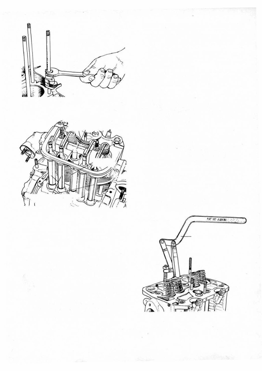
STUD REMOVAL PULLER 40010 FIG 1 :12 Removal of stud from crankcase by puller A.40010 FIG 1 :13 Engine without blower cowling and cylinder head cover .SPACER AND CONNECTION FOR ROCKER SHAFT LUBRICATION TUBE OILVAPOR .VENT PIPE CASINGS FOR PUSHRODS (AND OIL RETURN TO CRANKCASE 21 To ensure no damage occurs to the long cylinder barrel mounting studs these may be removed using Fiat puller A.40010 or a universal stud removal as shown in FIG 1 :12. 1 :5 Engine disassembly (station wagon) To dismantle the engine proceed as follows: 1 Remove the exhaust silencer and manifold by releasing the four nuts holding the two flanges from the cylinder head. Also disconnect the two silencer mounting brackets and lift away the exhaust system (see FIG 1 :2). 2 Place the engine on a firm wooden top bench. Release the clip holding the tappet cover and lift away together with the drip tray. Disconnect the fuel line and throttle linkage at the carburetter and carefully lift away the carburetter together with its insulator joint and gaskets. 3 Remove the generator drive belt by releasing the three nuts so splitting the semi-pulley. Lift away the drive belt. 16 FIG 1 :14 Tool A.60084 for valve and valve spring removal TOOL A. 60084 4 Remove all the bolts securing the air conveyor ducting to the cylinder head and to the crankcase, carefully separate the panels and lift away the separate panels ensuring no damage is caused to the mating faces. 5 Release the ignition distributor retaining bolt and lift away the distributor. 6 Remove the fuel pump retaining bolts and also the three fuel pipe retaining clips and lift away the fuel pump assembly together with the insulator, gaskets and control rod. 7 Release the two valve rocker retaining nuts, note the order of assembly of washers and ease away the rocker shaft assembly from the top of the cylinder head. Carefully lift out the valve rocker pushrods noting their relevent positions for correct reassembly. 8 Slacken the four cylinder head cap nuts and the four conventional nuts in the order shown in FIG 1 :46. Lift the cylinder head away from the barrels. If difficulty is experienced it is essential to use Fiat tool A.40014 or a similar drilled plate as shown in FIG 1 :9, otherwise serious damage could be caused if other means are used. 9 Remove the four pushrod sleeves and the casing con- taining the oil ducting to the overhead valve gear. 10 Remove the six screws holding the centrifugal oil filter pulley cover and lift away the cover. Remove the centrifugal filter mounting flange by unscrewing the crankshaft central bolt. Also remove the timing cover from the rear of the crankcase. Note carefully the posi- tion of the nuts, toothed and plain washers for correct reassembly. 11 Release the four camshaft sprocket retaining bolts and lift away the sprocket and timing chain. Using Fiat puller A.46020 or a large universal two-leg puller as shown in FIG 1 :10 remove the crankshaft sprocket and its key 12 Carefully lift out the rocker pushrod tappets making a note of their location and gently pull out the camshaft making sure that the front bearing bore is not damaged by the cam lobes.
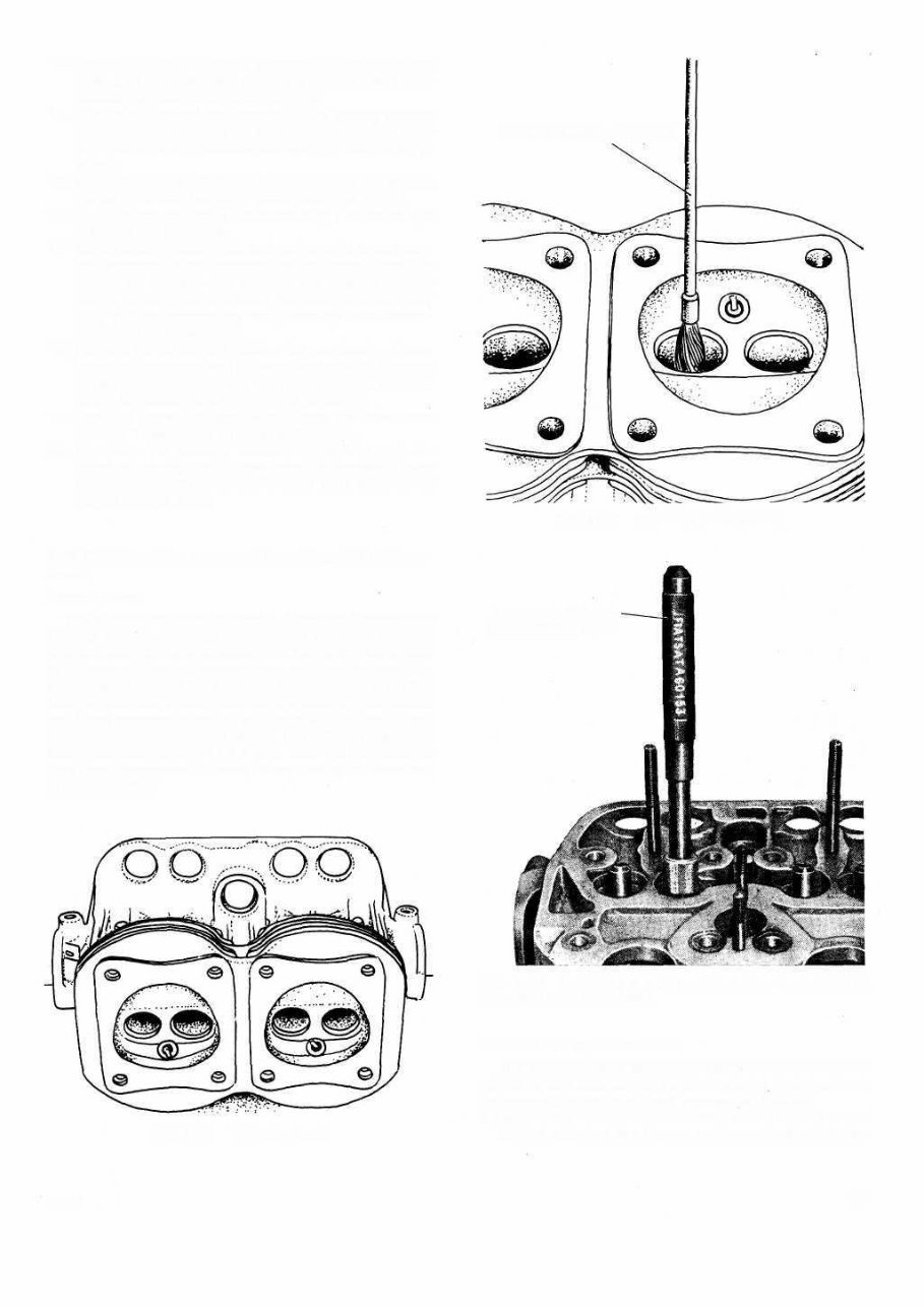
13 Remove all the bolts and washers joining the sump casting to the crankcase making a special note of the location of bolts of different lengths. 14 Mark the flywheel and crankshaft to ensure correct reassembly and release the six flywheel retaining bolts together with the lockwashers and lift away the fly- wheel. 15 Using Fiat tool A.60156 on the two central studs, lock the two cylinder barrels in place (see FIG 1 :11). 16 Turn the engine upside down ensuring that no weight is placed on the studs. 17 Mark the connecting rods and end caps to ensure cor- rect reassembly and remove the end caps. Place the engine on its side and remove the cylinder barrels clamp. Ensure that the studs are clean and carefully slide off the connecting rod-piston-cylinder assem- blies from the crankcase. 18 Remove the six screws holding the rear bearing hous- ing to the crankcase and lift away the housing. Remove the six screws holding the front main bearing housing to the crankcase and lift away its housing. 19 Carefully ease the crankshaft from the crankcase moving it diagonally to assist withdrawal. 20 To ensure no damage occurs to the long cylinder barrel mounting studs these may be removed using Fiat puller A.40010 or a universal stud remover as shown in FIG 1 :12. 1 :6 Cylinder head removal, servicing and replace- ment Description: The aluminium cylinder head is finned to increase the cooling surface. Through bolts secure the head and the two cylinders to the crankcase. The valves are controlled by a camshaft through tappets, pushrods and rockers. The connection between the head and the crankcase is via five sleeves mounted directly between the head and crankcase, and these accommodate the pushrods, lubricating oil and passage for the crankcase gases. The cylinder head has been modified for the 110 F and later 120 engines as they now incorporate a heater safety device as described in Section 4:4. FIG 1:15 Cylinder head 17 F500 The cylinder head should be removed whenever the valves require attention or the engine to be decarbonized. To remove the cylinder head proceed as follows: 1 Remove the air cleaner, carburetter, rocker cover and the screws securing the blower conveyor to the cylinder Removal of cylinder head: FIG 1 :17 Installing a valve guide using Tool A.60153 provided with pilot bush TOOL A. 60153- WITH PILOT BUSH FIG 1:16 Cleaning valve guides WIRE BRUSH A.11417 / BIS
The 1957-1973 Fiat Nouva 500 Service & Repair Manual is a comprehensive guide that provides detailed instructions and diagrams to assist you in maintaining and repairing your Fiat Nouva 500. Whether you are a professional mechanic or a novice car enthusiast, this manual will prove to be an invaluable resource for all your repair needs.
This manual covers various models of the Fiat Nouva 500, including:
Fiat Nouva 500 Pop
Fiat Nouva 500 Lounge
Fiat Nouva 500 Sport
Fiat Nouva 500 Abarth
Fiat Nouva 500 Cabrio
Fiat Nouva 500 Gucci
Fiat Nouva 500 1957 Edition
Each model is thoroughly explained, with step-by-step instructions and illustrations to guide you through every repair procedure. Covering everything from basic maintenance tasks to complex engine repairs, this manual ensures you have the technical information necessary to work confidently on your Fiat Nouva 500 from 1957 to 1973.
By utilizing the 1957-1973 Fiat Nouva 500 Service & Repair Manual, you can save time and money by performing repairs and maintenance on your own. No more costly trips to the mechanic—this manual empowers you to take control of your Fiat Nouva 500's upkeep and repair needs.
Order your copy of the 1957-1973 Fiat Nouva 500 Service & Repair Manual today and ensure your Fiat Nouva 500 continues to run smoothly for years to come.