2012 GENERAL INFORMATION Circuit Testing Procedures - Non-DTC-Based Diagnostics - Fiat 500 WARNING WARNING WARNINGS provide information to prevent personal injury and vehicle damage. Below is a list of general warnings that should be followed any time a vehicle is being serviced. DESCRIPTION WARNING: Always wear safety glasses for eye protection. WARNING: Use safety stands anytime a procedure requires being under a vehicle. WARNING: Be sure that the ignition switch always is in the off position, unless the procedure requires it to be on. WARNING: Set the parking brake when working on any vehicle. An automatic transmission should be in park. A manual transmission should be in neutral. WARNING: Operate the engine only in a well-ventilated area. WARNING: Keep away from moving parts when the engine is running, especially the fan and belts. WARNING: To prevent serious burns, avoid contact with hot parts such as the radiator, exhaust manifold(s), tail pipe, catalytic converter and muffler. WARNING: Do not allow flame or sparks near the battery. Gases are always present in and around the battery. WARNING: Always remove rings, watches, loose hanging jewelry and avoid loose clothing. 2012 Fiat 500
CIRCUIT FUNCTIONS All circuits in the diagrams use an alpha/numeric code to identify the wire and its function. To identify which circuit code applies to a system, refer to the Circuit Identification Code Chart. This chart shows the main circuits only and does not show the secondary codes that may apply to some models. CIRCUIT IDENTIFICATION CODE CHART CIRCUIT INFORMATION Each wire shown in the diagrams contains a code which identifies the main circuit, a specific part of the main circuit, gage of wire, and color. An example would be A 2 18 LB/YL . This is a Battery Feed circuit, level two, eighteen gauge, light blue with a yellow tracer. WIRE COLOR CODE CHART CIRCUIT FUNCTION A BATTERY FEED B BRAKE CONTROLS C CLIMATE CONTROLS D DIAGNOSTIC CIRCUITS E DIMMING ILLUMINATION CIRCUITS F FUSED CIRCUITS G MONITORING CIRCUITS (GAUGES) H MULTIPLE I NOT USED J OPEN K POWERTRAIN CONTROL MODULE L EXTERIOR LIGHTING M INTERIOR LIGHTING N MULTIPLE O NOT USED P POWER OPTION (BATTERY FEED) Q POWER OPTIONS (IGNITION FEED) R PASSIVE RESTRAINT S SUSPENSION/STEERING T TRANSMISSION/TRANSAXLE/ TRANSFER CASE U OPEN V SPEED CONTROL, WIPER/WASHER W WIPERS X AUDIO SYSTEMS Y TEMPORARY Z GROUNDS COLOR CODE COLOR
DIAGNOSIS AND TESTING DIAGNOSIS AND TESTING - WIRING HARNESS TESTING TROUBLESHOOTING TOOLS When diagnosing a problem in an electrical circuit there are several common tools necessary. These tools are listed and explained below. Jumper Wire - This is a test wire used to connect two points of a circuit. It can be used to bypass an open in a circuit. Voltmeter - Used to check for voltage on a circuit. Always connect the black lead to a known good ground and the red lead to the positive side of the circuit. Ohmmeter - Used to check the resistance between two points of a circuit. Low or no resistance in a circuit means good continuity. BL BLUE BK BLACK BR BROWN DB DARK BLUE DG DARK GREEN GY GRAY LB LIGHT BLUE LG LIGHT GREEN OR ORANGE PK PINK RD RED TN TAN VT VIOLET WT WHITE YL YELLOW * WITH TRACER WARNING: Never use a jumper wire across a load, such as a motor, connected between a battery feed and ground. CAUTION: Most of the electrical components used in today's vehicles are Solid State. When checking voltages in these circuits, use a meter with a 10 - megohm or greater impedance rating. CAUTION: Most of the electrical components used in today's vehicles are Solid State.
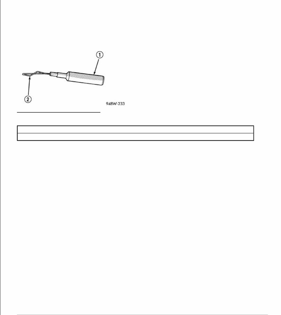
Fig. 1: Special Tool & Probing End Courtesy of CHRYSLER GROUP, LLC Probing Tools - These tools are used for probing terminals in connectors. Select the proper size tool from Special Tool Package (special tool #6807, Terminal Tools), and insert the probing end (2) into the terminal being tested. Use the other end of the tool (1) to insert the meter probe. INTERMITTENT AND POOR CONNECTIONS Most intermittent electrical problems are caused by faulty electrical connections or wiring. It is also possible for a sticking component or relay to cause a problem. Before condemning a component or wiring assembly, check the following items. Connectors are fully seated Spread terminals, or terminal push out Terminals in the wiring assembly are fully seated into the connector/component and locked into position Dirt or corrosion on the terminals. Any amount of corrosion or dirt could cause an intermittent problem Damaged connector/component casing exposing the item to dirt or moisture Wire insulation that has rubbed through causing a short to ground Some or all of the wiring strands broken inside of the insulation Wiring broken inside of the insulation When checking resistance in these circuits use a meter with a 10 - megohm or greater impedance rating. In addition, make sure the power is disconnected from the circuit. Circuits that are powered up by the vehicle's electrical system can cause damage to the equipment and provide false readings. 1 - SPECIAL TOOL 6801 2 - PROBING END
TROUBLESHOOTING WIRING PROBLEMS When troubleshooting wiring problems there are six steps which can aid in the procedure. The steps are listed and explained below. Always check for non-factory items added to the vehicle before doing any diagnosis. If the vehicle is equipped with these items, disconnect them to verify these add-on items are not the cause of the problem. 1. Verify the problem. 2. Verify any related symptoms. Do this by performing operational checks on components that are in the same circuit. Refer to the appropriate wiring diagrams. 3. Analyze the symptoms. Use the wiring diagrams to determine what the circuit is doing, where the problem most likely is occurring and where the diagnosis will continue. 4. Isolate the problem area. 5. Repair the problem area. 6. Verify the proper operation. For this step, check for proper operation of all items on the repaired circuit. Refer to the appropriate wiring diagrams. STANDARD PROCEDURE CHECK A BATTERY OR IGNITION VOLTAGE CIRCUIT WITH A 12-VOLT TEST LIGHT DIAGNOSTIC TEST
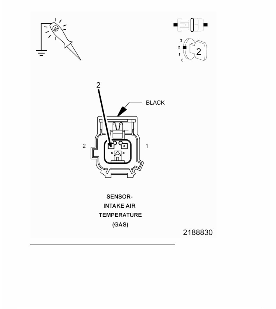
Fig. 2: Using Test Light To Check Battery Or Ignition Voltage Courtesy of CHRYSLER GROUP, LLC 1. 1. Turn the ignition off. 2. Disconnect the wire harness connector of the component that is receiving the voltage. NOTE: Check connectors - Clean/repair as necessary.
3. At this time, leave all in-line connectors connected. 4. Connect the 12-volt test light to a known good ground. 5. Use the test light lead to carefully probe the Battery or Ignition Voltage circuit in the harness connector. 6. First check with the ignition off, next check with the ignition on, and lastly check while cranking the engine. Does the test light illuminate brightly? Yes The circuit is not open at this time or the condition that originally caused the open may not be present at this time. Continue to monitor the test light and wiggle the wire harness and connectors to check for an intermittent open or excessive resistance condition. Use the wiring application as a guide to trace the circuits and look for any in-line connectors where the open could occur intermittently. Look for any chafed, pierced, pinched, or partially broken wires. Look for broken, bent, pushed out or corroded terminals. Verify that there is good pin to terminal contact in the related wire harness connectors. Perform any Technical Service Bulletins (TSBs) that may apply. No Repair the open in the circuit. Use the wiring application as a guide to trace the circuit and look for any in-line connectors where the short could occur. One way to help isolate the open is to disconnect any in-line connectors and measure the resistance from one side of the in-line connector to the matching component harness connector. If the open goes away, the open is on the other side of the in-line connector. If this is a fused circuit, make sure to inspect the fuse. If the fuse is open, check the circuit for a short to ground before installing a new fuse. The circuit may have a short to ground causing the fuse to open. This short to ground could be in the wire harness or in one of the components the circuit is supplying voltage to. CHECK A CIRCUIT FOR A SHORT TO GROUND DIAGNOSTIC TEST NOTE: Before inspecting any circuits, first test the 12-volt test light. Connect the 12-volt test light to battery ground or to any other known good ground. Touch the lead of the test light to Battery +. If the test light is good, it should illuminate brightly.
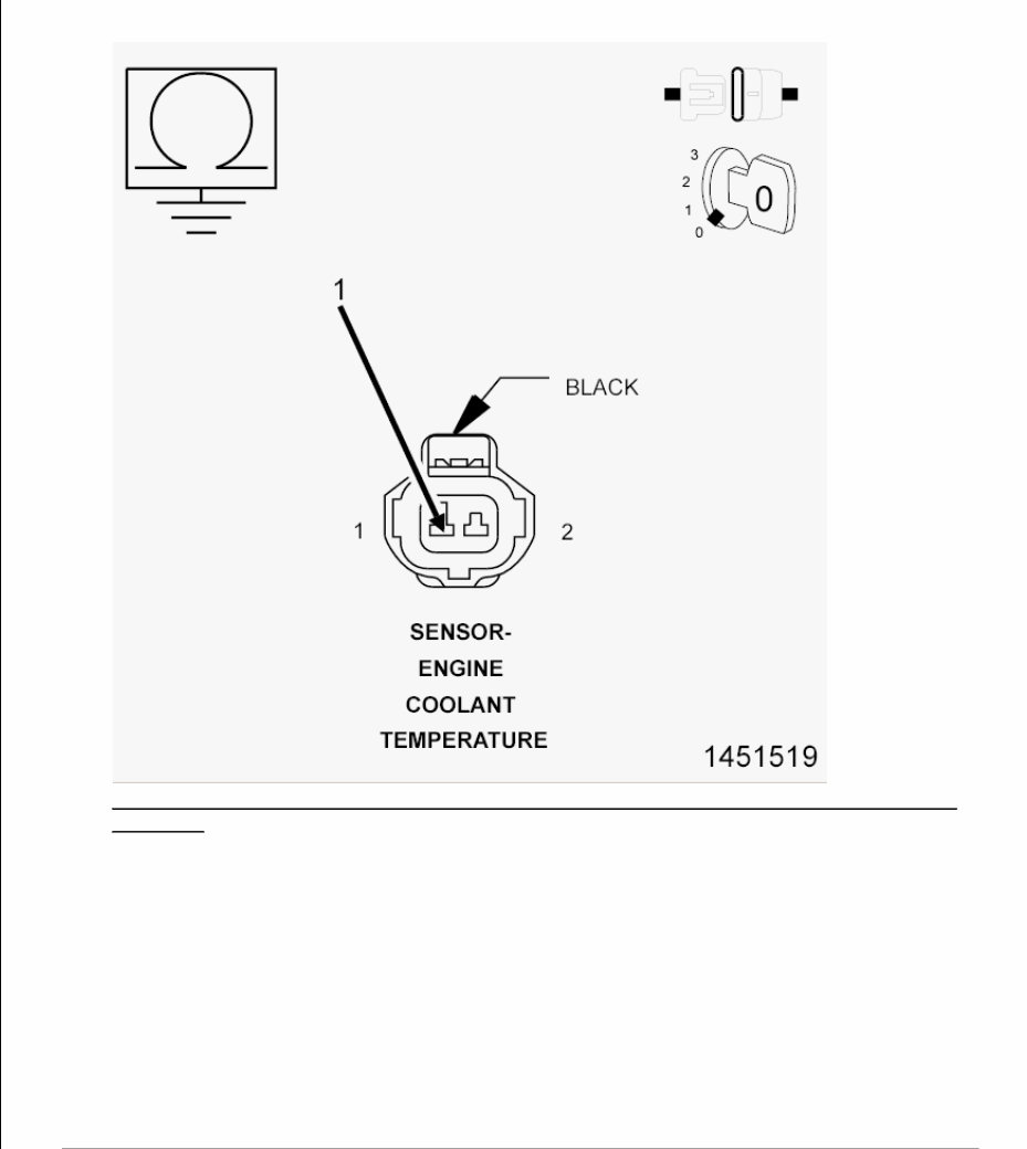
Fig. 3: Measuring Resistance Between Ground And ECT Sensor Signal Circuit In Sensor Harness Connector Courtesy of CHRYSLER GROUP, LLC 1. 1. Turn the ignition off. 2. Disconnect the wire harness connectors of the components that contain the circuit suspected as being shorted to ground. NOTE: Check connectors - Clean/repair as necessary. NOTE: Before checking the circuit for a short to ground, first measure the resistance between the two leads of the multimeter. Take this value and subtract it from the value recorded when measuring the
3. With the component wire harness connectors disconnected, use a meter set to measure Ohms (ohms), and measure the resistance between the circuit and a known good ground. 4. Use the negative lead of the meter and touch a known good ground. 5. Use the positive lead of the meter and carefully probe the circuit suspected as having the short. Is the resistance to ground below 10k Ohms ? Yes Repair the short to ground. Use the wiring application as a guide to follow the path of the circuit. One way to help isolate the short is to disconnect any in-line connectors that the circuit being tested runs through and measure for the short again. If the short goes away, the short is on the other side of the in-line connector. No The circuit is not shorted to ground or the condition that originally caused the short may not be present at this time. Continue to measure the resistance, wiggle the wire harness and connectors while checking for an intermittent short. Use the wiring application as a guide to trace the circuits and look for any in-line connectors where the short could occur intermittently. Look for any chafed, pierced, pinched, or partially broken wires. Look for broken, bent, pushed out or corroded terminals. Verify that there is good pin to terminal contact in the related wire harness connectors. Perform any Technical Service Bulletins (TSBs) that may apply. CHECK A CIRCUIT FOR VOLTAGE THEORY OF OPERATION resistance between ground and the circuit being checked. The leads of the meter can add up to or over 0.5 of an Ohm of resistance.
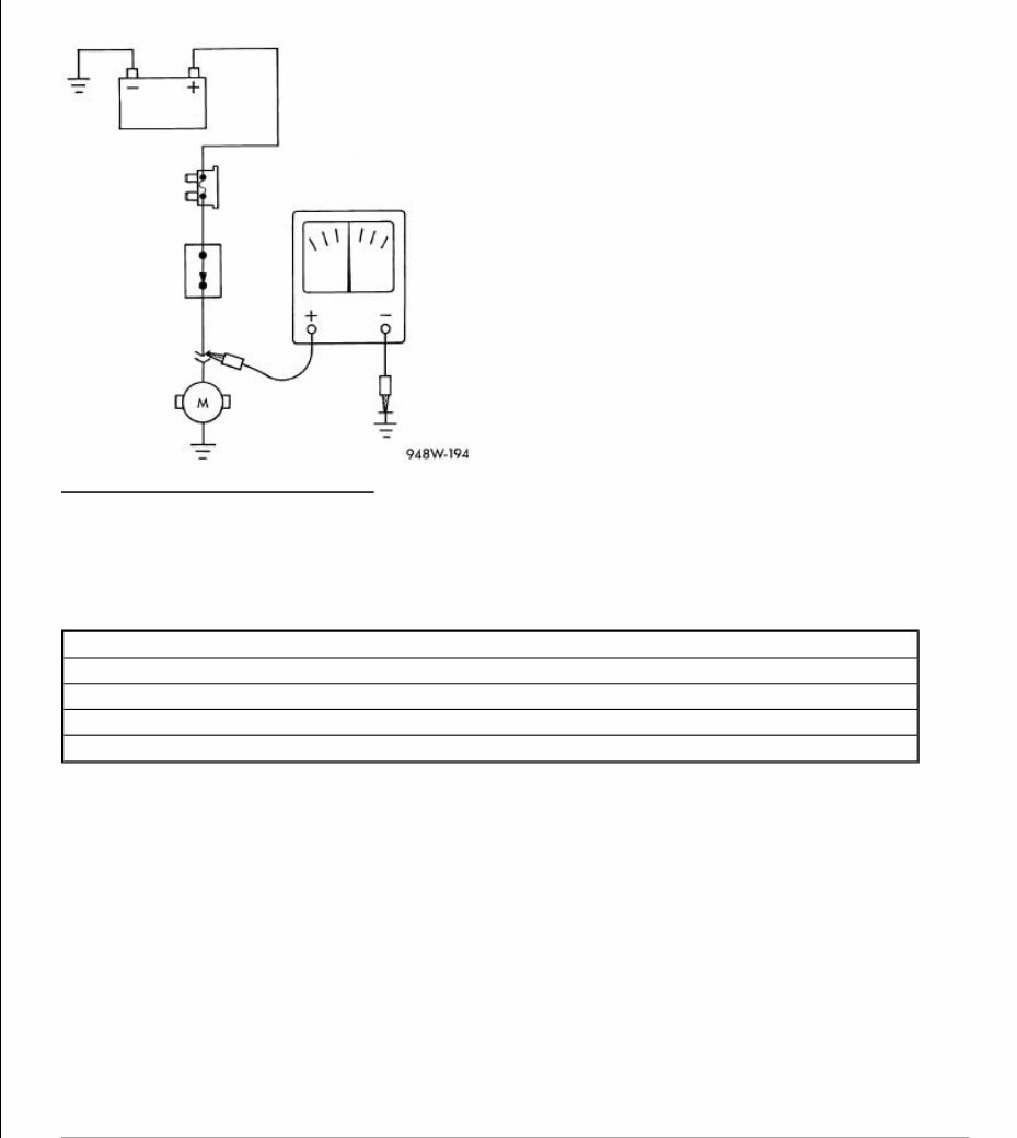
Fig. 4: Testing For Voltage Potential Courtesy of CHRYSLER GROUP, LLC The purpose for the following procedure is to show different methods of checking the voltage of a circuit. When diagnosing a DTCs it might be necessary to verify that proper voltage is on a circuit or that a circuit is not shorted high. Below are four examples of checking the voltage in a circuit. DIAGNOSTIC TEST 1. CHECKING FOR VOLTAGE Test Procedures CHECKING FOR VOLTAGE ON A CIRCUIT. Refer to1. CHECKING FOR A SHORT TO BATTERY VOLTAGE USING A MULTIMETER. Refer to2. CHECKING FOR A SHORT TO IGNITION VOLTAGE USING A MULTIMETER. Refer to3. CHECKING FOR A SHORT TO VOLTAGE USING A 12-VOLT TEST LIGHT. Refer to4.
Discover the essential 2012-2015 Fiat 500 Service & Repair Manual, your go-to resource for maintaining and fixing your Fiat 500. This comprehensive manual encompasses various Fiat 500 models from 2012 to 2015, ensuring that regardless of your model, you'll have the necessary information to keep it running smoothly.
Equipped with detailed step-by-step instructions, diagrams, and illustrations, this manual simplifies routine maintenance and complex repairs. Whether it's an oil change, belt replacement, or electrical troubleshooting, you'll find all the vital information at your fingertips.
Highlighted models covered in this manual:
2012 Fiat 500 Pop
2012 Fiat 500 Lounge
2013 Fiat 500 Sport
2013 Fiat 500 Turbo
2014 Fiat 500 Abarth
2014 Fiat 500L Trekking
2015 Fiat 500C Abarth
2015 Fiat 500X Lounge
Whether you're a professional mechanic or a dedicated DIY enthusiast, the 2012-2015 Fiat 500 Service & Repair Manual is an indispensable tool for maintaining your Fiat 500. Don't let maintenance and repairs hinder you - acquire the manual today and take charge of your Fiat 500's performance!