1969-1974 Fiat Spider 124 BS Electrical Wiring Diagram Manual
What's Included?
Lifetime Access
Fast Download Speeds
Online & Offline Access
Access PDF Contents & Bookmarks
Full Search Facility
Print one or all pages of your manual
WIRING DIAGRAMS FIAT SPIDER 124 TYPE BS (1969 – 1973) OCTOBER 2006 BRADLEY J. ARTIGUE
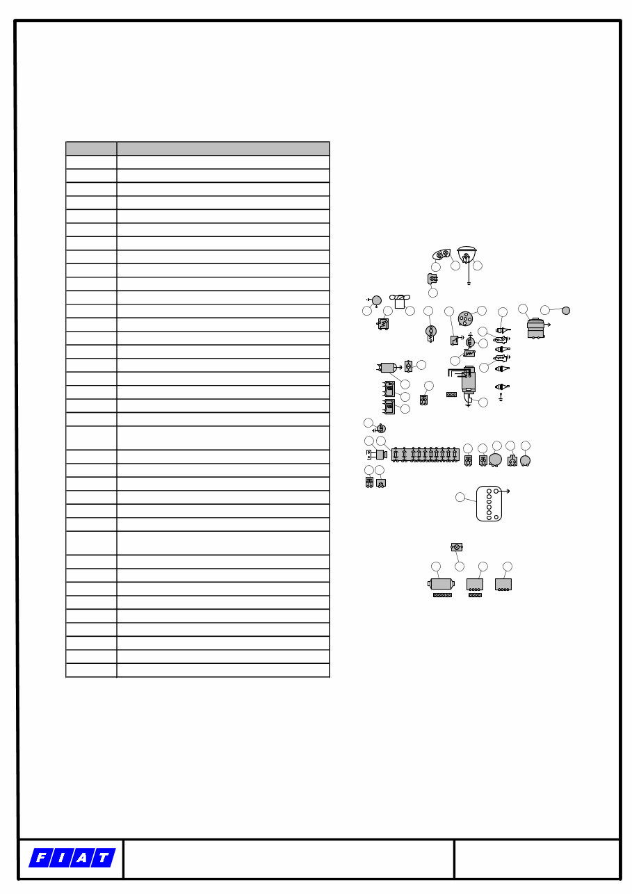
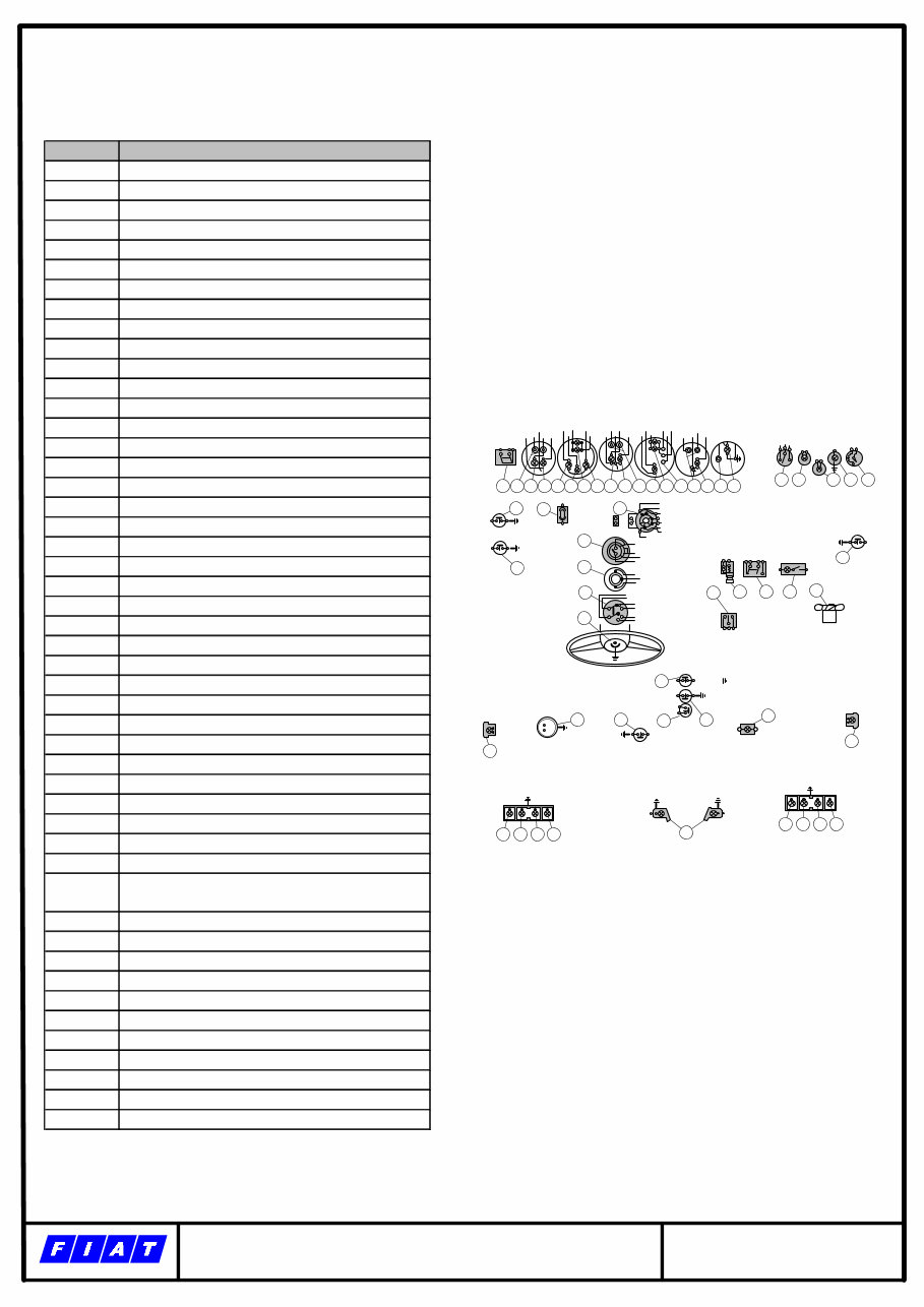
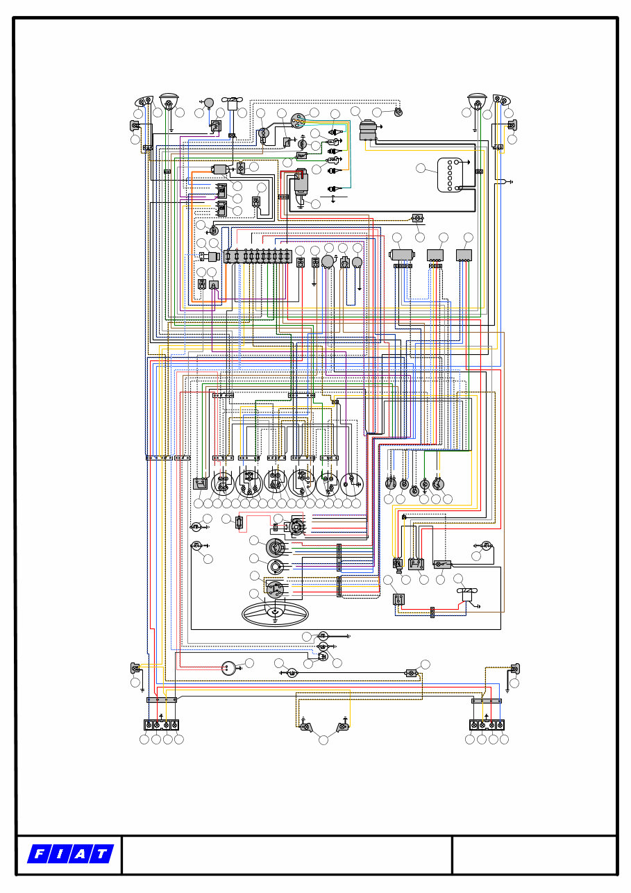
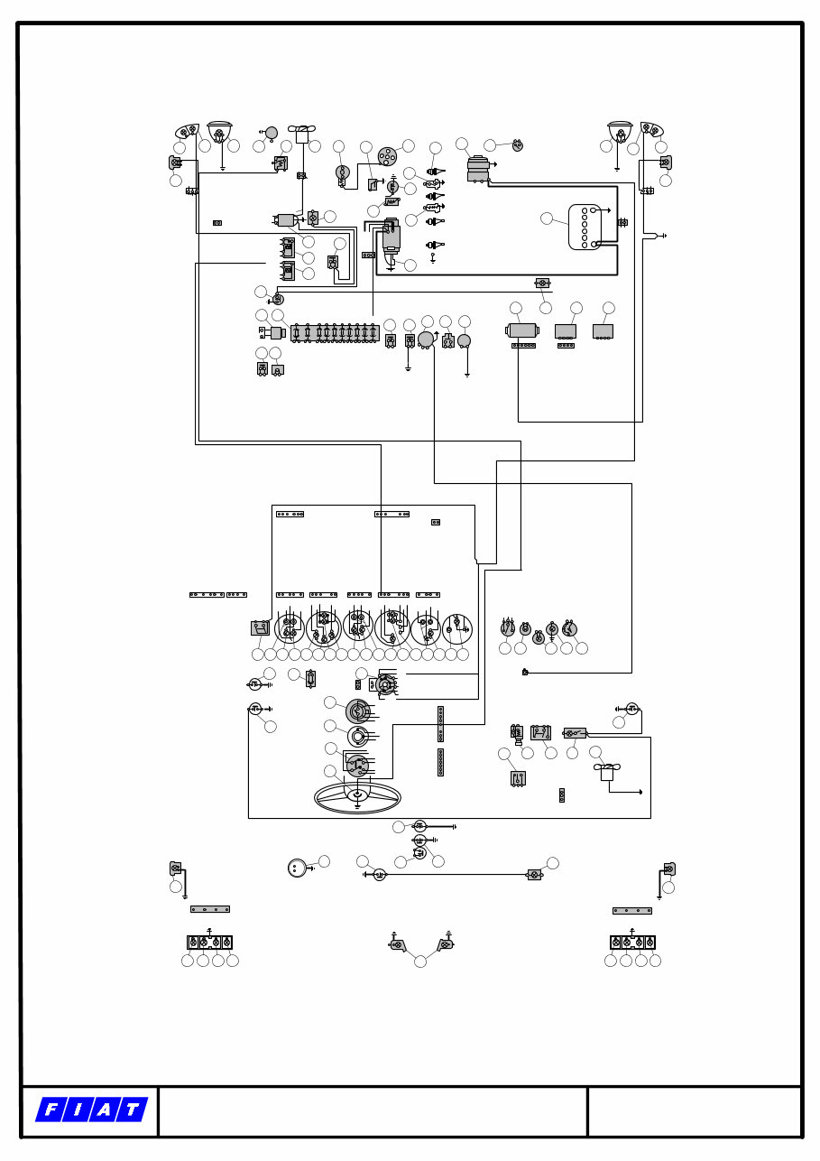
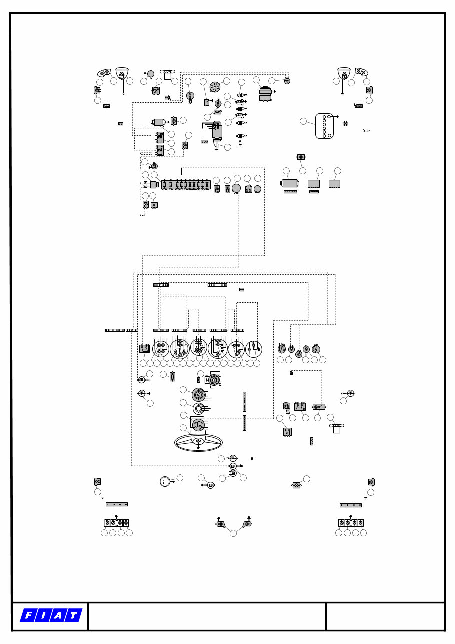
DIAGRAM INDEX The wiring diagram provided herein is presented first in the original, “all wires” format, and subsequently with one drawing per wire color. Given the numerous wiring colors and the density of wiring in the main diagram it is highly recommended to use a color printer of sufficient resolution and high quality paper for best output. COMPONENTS A DIAGRAM SHOWING ONLY THE VEHICLES COMPONENTS AND A LEGEND FOR EACH COMPONENT NUMBER COMPLETE AN “ALL WIRES” DIAGRAM AS ORIGINALLY PROVIDED BY FIAT COLOR DIAGRAMS ONE DIAGRAM PER LINE COLOR: BLACK BLACK/WHITE BROWN DARK BLUE GRAY GRAY/BLACK GRAY/RED GREEN GREEN/BLACK LIGHT BLUE LIGHT BLUE/BLACK LIGHT BLUE/RED ORANGE PINK RED VIOLET WHITE YELLOW YELLOW/BLACK IGNITION IGNITION COMPONENTS DETAIL DIAGRAM
1969 – 1973 COMPONENTS 1-37 http://www.artigue.com/fiat 28 29 30 31 P L 32 33 34 35 16 C 31 INT F B 36 1 346 25 +P 37 26 27 25 L M F G E D C B A I 10 8 6 7 5 4 3 2 1 9 21 16 22 23 20 15 67 50 30 24 17 15 9 8 1 2 3 4 +B D 7 6 5 4 13 1 2 3 1 2 3 4 14 18 12 11 30 57 19 10 87 86 85 30/51 30/51 85 86 87 4 3 1 Com ponent Description 1 Front direction Indicators. 2 Front parking lights 3 Headlamps (high and low beams) 4 Motorcompressor for electropneumatic horns 5 Horn control relay switch 6 Engine cooling fan m otor 7 IgnItion coil. 8 Oil Pressure Gauge sending unit 9 Ignition Distributor 10 Spark plugs 11 Alternator 12 Engine fan motor thermostatic switch 13 Front side marker lamps 14 Heat gauge thermostatic switch 15 Insufficient Oil Pressure indicator sending unit 16 Engine com partm ent lam ps 17 Heat gauge additional resistor 18 Heat Gauge s ending unit 19 Battery charge Indicator relay. 20 Voltage regulator 21 Button switch for electrovaive energizing during fast idie rate adjustments. 22 Engine fan motor relay switch 23 Battery charge Indicator relay. 24 Starter Motor 25 Engine compartment lamps jam switch. 26 Electrovalve, exhaust emission control device 27 Fuses 28 Switch on clutch pedal for exhaust emission control electropneumatic s ys tem 29 Ins pection lamp receptacle 30 Stop lights switch 31 Switch, on the hydraulic circuit, for indicator 57. 32 Flasher, direction indicators. 33 WIndshield washer motor button switch 34 Electric pump, windshield washer. 35 WIndshield wiper motor. 36 Windshield wiper Intermittent operation cycling switch unit. 37 Flasher, indicator 57,
1969 – 1973 COMPONENTS 38-85 http://www.artigue.com/fiat 81 82 83 84 80 84 83 82 81 80 85 79 77 78 74 76 W T 75 64 72 71 70 69 67 m 68 l s o n p 62 66 65 64 61 63 h a e b d g c 30/1 15 50 30 INT 38 39 40 41 42 43 44 45 46 47 48 49 50 51 52 53 54 55 56 57 58 59 60 73 V I N R S BN GN B G B BN VN A H HN BN GN B N AN B GN BN M V BN GN B TLH AE Com ponent Des cription 38 Outer lighting 2 position switch 39 Fuel Gauge 40 Fuel Reserve Indicator 41 Fuel Gauge Light 42 ParkIng lights Indicator (green). 43 DIrectional s ignal arrow tell tale (green), 44 Speedometer light 45 Headlamp high beam Indicator (blue) 46 Insufficient oil pressure Indicator (red). 47 Oil pressure gauge light 48 Oil pressure gauge 49 Battery charge indicator (red). 50 Engine tachom eter light. 51 Engine tachom eter. 52 Engine water heat gauge. 53 Engine water heat gauge light. 54 Clock, 55 Clock light, 56 WIndshield wiper high end low sweep rate control, 57 Brake system effectiveness and hand brake ON indicator (red). 58 Rem ove key Indicator 59 Vehicular hazard warning signal indicator. 60 Panel light rheostatic switch, 61 Jam switch, on left door pillar, for Indicator 58 62 Separate 3 Amp fuse for indicator 58 and Its switch. 63 Lock switch. 64 Jam switches, between doors and pillars, for courtesy lights. 65 Headlamp high-low beam change-over and low beam flas hes s witch. 66 Direction Indicators switch. 67 WIndshield wiper control three-position switch. 68 Electropnaumatlc horn control button. 69 Electrofan 3-position switch. 70 ElectrIc cigarette lighter (with housing Indicator). 71 Vehicular hazard warning signal switch. 72 Courtesy light, with Incorporated switch. 73 Electrofan motor, two.speed, 74 Switch, on transmission (3rd and 4th gears) for exhaust emissIon control electropneumatic system. 75 Fuel gauge sandIng unit, 76 Luggage compartment lamp jam switch. 77 Back-up light switch 78 SwItch, on hand brake Iever, for indicator 57, 79 Luggage com partm ent lam p, 80 Rear side marker lamps. 81 Rear direction indicators. 82 Rear stop lights. 83 Rear parking lights . 84 Back-up lights . 85 Number plate lIghts.
1969 – 1973 COMPLETE WIRING http://www.artigue.com/fiat 81 82 83 84 80 84 83 82 81 80 85 79 77 78 74 76 W T 75 64 72 71 70 69 67 m 68 l s o n p 62 66 65 64 61 63 h a e b d g c 30/1 15 50 30 INT 38 39 40 41 42 43 44 45 46 47 48 49 50 51 52 53 54 55 56 57 58 59 60 28 29 30 31 P L 32 33 34 35 16 C 31 INT F B 36 1 346 25 +P 37 26 27 25 L M F G E D C B A I 10 8 6 7 5 4 3 2 1 9 21 16 22 23 20 15 67 50 30 24 17 15 9 8 1 2 3 4 +B D 7 6 5 4 13 1 2 3 1 2 3 4 14 18 12 11 30 57 19 13 1 2 3 73 10 87 86 85 30/51 30/51 85 86 87 4 1 V I N R S BN GN B G B BN VN A H HN BN GN B N AN B GN BN M V BN GN B TL H AE 3 CYLINDER HEAD GROUND TO BODY
1969 – 1973 BLACK WIRING http://www.artigue.com/fiat 81 82 83 84 80 84 83 82 81 80 85 79 77 78 74 76 W T 75 64 72 71 70 69 67 m 68 l s o n p 62 66 65 64 61 63 h a e b d g c 30/1 15 50 30 INT 38 39 40 41 42 43 44 45 46 47 48 49 50 51 52 53 54 55 56 57 58 59 60 28 29 30 31 P L 32 33 34 35 16 C 31 INT F B 36 1 346 25 +P 37 26 27 25 L M F G E D C B A I 10 8 6 7 5 4 3 2 1 9 21 16 22 23 20 15 67 50 30 24 17 15 9 8 1 2 3 4 +B D 7 6 5 4 13 1 2 3 1 2 3 4 14 18 12 11 30 57 19 13 1 2 3 73 10 87 86 85 30/51 30/51 85 86 87 4 3 1 V I N R S BN GN B G B BN VN A H HN BN GN B N AN B GN BN M V BN GN B TL H AE Black
1969 – 1973 BLACK/WHITE WIRING http://www.artigue.com/fiat 81 82 83 84 80 84 83 82 81 80 85 79 77 78 74 76 W T 75 64 72 71 70 69 67 m 68 l s o n p 62 66 65 64 61 63 h a e b d g c 30/1 15 50 30 INT 38 39 40 41 42 43 44 45 46 47 48 49 50 51 52 53 54 55 56 57 58 59 60 28 29 30 31 P L 32 33 34 35 16 C 31 INT F B 36 1 346 25 +P 37 26 27 25 L M F G E D C B A I 10 8 6 7 5 4 3 2 1 9 21 16 22 23 20 15 67 50 30 24 17 15 9 8 1 2 3 4 +B D 7 6 5 4 13 1 2 3 1 2 3 4 14 18 12 11 30 57 19 13 1 2 3 73 10 87 86 85 30/51 30/51 85 86 87 4 3 1 V I N R S BN GN B G B BN VN A H HN BN GN B N AN B GN BN M V BN GN B TL H AE White Black White Black
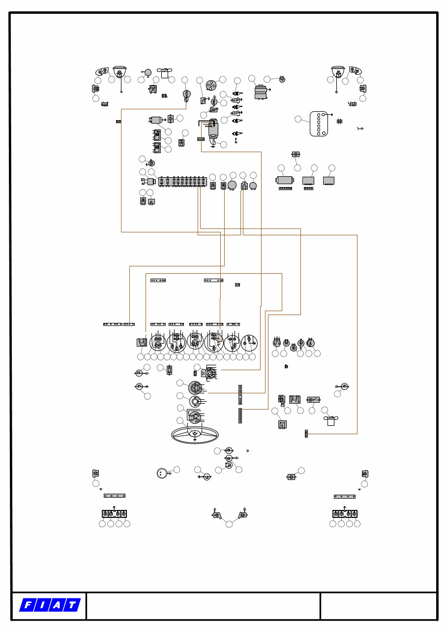
1969 – 1973 BROWN WIRING http://www.artigue.com/fiat 81 82 83 84 80 84 83 82 81 80 85 79 77 78 74 76 W T 75 64 72 71 70 69 67 m 68 l s o n p 62 66 65 64 61 63 h a e b d g c 30/1 15 50 30 INT 38 39 40 41 42 43 44 45 46 47 48 49 50 51 52 53 54 55 56 57 58 59 60 28 29 30 31 P L 32 33 34 35 16 C 31 INT F B 36 1 346 25 +P 37 26 27 25 L M F G E D C B A I 10 8 6 7 5 4 3 2 1 9 21 16 22 23 20 15 67 50 30 24 17 15 9 8 1 2 3 4 +B D 7 6 5 4 13 1 2 3 1 2 3 4 14 18 12 11 30 57 19 13 1 2 3 73 10 87 86 85 30/51 30/51 85 86 87 4 3 1 V I N R S BN GN B G B BN VN A H HN BN GN B N AN B GN BN M V BN GN B TL H AE
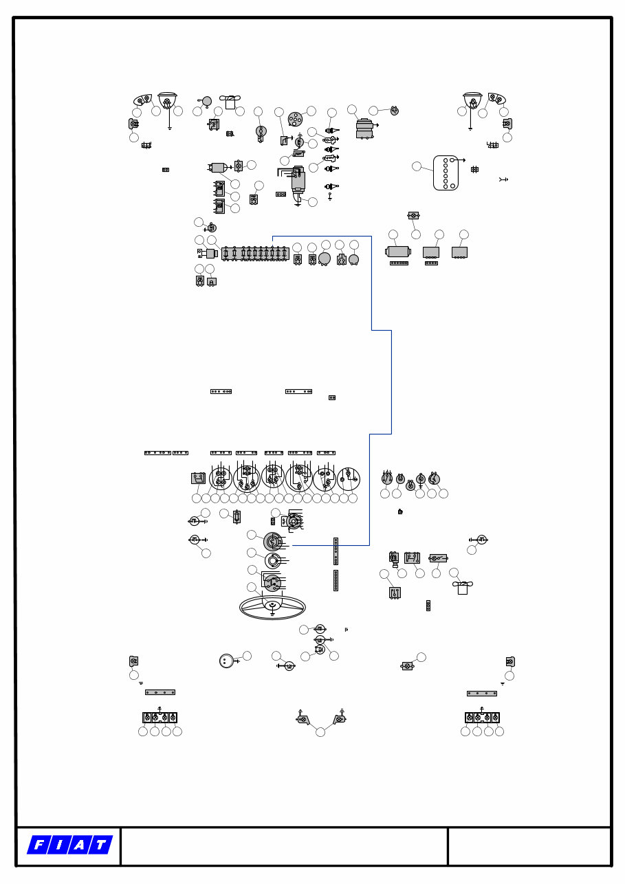
1969 – 1973 DARK BLUE WIRING http://www.artigue.com/fiat 81 82 83 84 80 84 83 82 81 80 85 79 77 78 74 76 W T 75 64 72 71 70 69 67 m 68 l s o n p 62 66 65 64 61 63 h a e b d g c 30/1 15 50 30 INT 38 39 40 41 42 43 44 45 46 47 48 49 50 51 52 53 54 55 56 57 58 59 60 28 29 30 31 P L 32 33 34 35 16 C 31 INT F B 36 1 346 25 +P 37 26 27 25 L M F G E D C B A I 10 8 6 7 5 4 3 2 1 9 21 16 22 23 20 15 67 50 30 24 17 15 9 8 1 2 3 4 +B D 7 6 5 4 13 1 2 3 1 2 3 4 14 18 12 11 30 57 19 13 1 2 3 73 10 87 86 85 30/51 30/51 85 86 87 4 3 1 V I N R S BN GN B G B BN VN A H HN BN GN B N AN B GN BN M V BN GN B TL H AE
The FIAT SPIDER 124 BS 1969-1974 Wiring Diagrams is a comprehensive collection of wiring diagrams specifically designed for the FIAT SPIDER 124 BS models produced between 1969 and 1974. These diagrams provide a detailed visual representation of the electrical systems and circuits of the vehicle.
These wiring diagrams are essential for understanding the electrical components and connections in the FIAT SPIDER 124 BS. Whether you are a DIY enthusiast or a professional mechanic, these diagrams will provide you with the necessary information to troubleshoot electrical issues, repair faulty connections, or modify the electrical system of the vehicle.
With the FIAT SPIDER 124 BS 1969-1974 Wiring Diagrams, you can easily locate and identify various electrical components, such as fuses, relays, switches, and wiring harnesses. The diagrams provide clear and concise representations of the wiring routes, color codes, and connections, making it easy to follow and understand.
FIAT SPIDER 124 BS 1969
FIAT SPIDER 124 BS 1970
FIAT SPIDER 124 BS 1971
FIAT SPIDER 124 BS 1972
FIAT SPIDER 124 BS 1973
FIAT SPIDER 124 BS 1974
No matter the model year of your FIAT SPIDER 124 BS, these wiring diagrams will guide you through the electrical system, helping you diagnose and resolve any electrical problems you may encounter. They are an indispensable tool for any FIAT SPIDER 124 BS owner or mechanic!
Recently Viewed
5,521,897Happy Clients
2,594,462eManuals
1,120,453Trusted Sellers
15Years in Business
Price:
Actual Price:
1969-1974 Fiat Spider 124 BS Electrical Wiring Diagram Manual