IMPORT SERVICE MANUAL STEALTH ENGINE, CHASSIS & BODY Volume - I
SAFETY NOTICE CAUTION ALL SERVICE AND REBUILDING INSTRUCTIONS CONTAINED HEREIN ARE APPLICABLE TO, AND FOR THE CONVENIENCE OF, THE AUTOMOTIVE TRADE ONLY. All test and repair procedures on components or assemblies in non-automotive applications should be repaired in accordance with instructions supplied by the manufacturer of the total product. Proper service and repair is important to the safe, reliable, operation of all motor vehicles. The service procedures recommended and described in this publication were developed for professional service personnel and are effective methods for performing vehicle repair. Following these procedures will help assure efficient economical vehicle performance and service reliability. Some of these service procedures require the use of special tools designed for specific procedures. These special tools should be used when recommended throughout this publication. Special attention should be exercised when working with spring or tension loaded fasteners and devices such as E-Clips, Circlips, Snap rings, etc., as careless removal may cause personal injury. Always wear safety goggles whenever working on vehicles or vehicle components. It is important to note that this publication contains various Cautions and Warnings. These should be carefully read in order to minimize the risk of personal injury, or the possibility that improper service methods may damage the vehicle or render it unsafe. It is important to note that these Cautions and Warnings cover only the situations and procedures Chrysler Corporation has encountered and recommended. Chrysler Corporation could not possibly know, evaluate, and advise the service trade of all conceivable ways that service may be performed, or of the possible hazards of each. Consequently, Chrysler Corporation has not undertaken any such broad service review. Accordingly, anyone who uses a service procedure, or tool, that is not recommended in this publication must assure oneself thoroughly that neither personal safety, nor vehicle safety, be jeopardized by the service methods they select. SERVICE AND OWNER MANUALS A vailable for Chrysler, Plymouth, Dodge, Dodge Truck, Jeep, and Eagle vehicles. Telephone orders may be placed at the number below. Credit cards are accepted (no CODS). Please have your order information available at time of call. ” ,’ ? CALL: (218) 572-7240 OR FAX: (218) 572-0815 FOR A FREE CATALOG OR TO PLACE AN ORDER.
BackupService Manual GROUP INDEX Stealth 1994 Volume-1 Engine, Chassis & Body FOREWORD This Service Manual has been prepared with the latest service information available at the time of publication. It is subdivided into various group categories and each section contains diagnosis, disassembly, repair, and installation procedures along with complete specifications and tightening references. Use of this manual will aid in properly performing any servicing necessary to maintain or restore the high levels of performance and reliability designed into these outstanding vehicles. 1, CHRYSLER b!!d CORPORATION Introduction and Master Troubleshooting *****..***.**.***.*. Lubrication and Maintenance . . . . . . . . Front Suspension . . . . . . . . . . . . . . . . . . . . . . . . . . . . . . . . Rear Axle . . . . . . . . . . . . . . . . . . . . . . . . . . . . . . . . . . . . . . . . . . . . Service Brakes - Parking . . . . . . . . . . . . . . . . . . . . . . . . . . . . . . . . Clutch . . . . . . . . . . . . . . . . . . . . . . . . . . . . . . . . . . . . . . . . . . . . . . . . . . . . Cooling . . . . . . . . . . . . . . . . . . . . . . . . . . . . . . . . . . . . . . . . . . . . . . . . Engine . . . . . . . . . . . . . . . . . . . . . . . . . . . . . . . . . . . . . . . . . . . . . . . . . . . . Intake and Exhaust . . . . . . . . . . . . . . . . . . . . . . . . . . . . Fuel System ........................................ Propeller Shaft and Universal Joints ................................. Rear Suspension ................................ Steering . . . . . . . . . . . . . . . . . . . . . . . . . . . . . . . . . . . . . . . . . . . . . . . . Manual Transaxle- Automatic . . . . . . . . . . . . . . . . . . . . Wheels and Tires . . . . . . . . . . . . . . . . . . . . . . . . . . . . . . . . Body and Supplemental Restraint System (SRS) ....*.*.*.***.****** Heaters and Air Conditioning . . . . . . . . Emission Control Systems . . . . . . . . . . . . Chrysler Corporation reserves the right to make changes In design or to make additions to or improvements in its products without imposing any obligations upon itself to install them on its products oreviouslv manufactured. I @ 1993 Mitsubishi Motors Corporation 1 NOTE: I Printed in Japan For Electrical, refer to Volume-2 “Electrical”.
2 INTRODUCTION AND MASTER TROUBLESHOOTING Warnings Regarding Servicing of Supplemental - Restraint Svstem k?RSl Equipped Vehicles WARNINGS REGARDING SERVICING OF SUPPLEMENTAL RESTRAINT SYSTEM (SRS) EQUIPPED VEHICLES d WARNING! (1) Improper service or maintenance of any component of the SRS, or any SRS-related component, can lead to personal injury or death to service personnel (from inadvertent firing of the air bag) or to the driver (from rendering the SRS inoperative). (2) If it is possible that the SRS components are subjected to heat over 93°C (200°F) in baking or in drying after painting, remove the SRS components (air bag module, SRS diagnosis unit, front impact sensors) beforehand. (3) Service or maintenance of any SRS component or SRS-related component must be performed only at an authorized CHRYSLER dealer. (4) CHRYSLER dealer personnel must thoroughly review this manual, and especially its GROUP 23B - Supplemental Restraint System (SRS) and GROUP 0 - Maintenance Service, before beginning any service or maintenance of any component of the SRS or any SRS-related component. NOTE Section titles with asterisks (*) in the table of contests in each group indicate operations requiring warnings.
INTRODUCTION AND MASTER TROUBLESHOOTING - How to Use This Manual 3 HOW TO USE MAINTENANCE, REPAIR AND SERVIC- ING EXPLANATIONS This manual provides explanations, etc. concerning procedures for the inspection, maintenance, repair and servicing of the subject model. Unless other- wise specified, each service procedure covers all models. Procedures covering specific models are identified by the model codes, or similar designation (engine type, transaxle type, etc.). A description of these designations is covered in this manual under “VEHICLE IDENTIFICATION”. SERVICE ADJUSTMENT PROCEDURES “Service Adjustment Procedures” are procedures for performing inspections and adjustments of particularly important locations with regard to the construction and for maintenance and servicing, but other inspections (for looseness, play, cracking, damage, etc.) must also be performed. SERVICE PROCEDURES The service steps are arranged in numerical order and attention must be paid in performing vehicle service are described in detail in SERVICE POINTS. TROUBLESHOOTING ’ Troubleshootings are classified into master trouble- shooting and group troubleshooting and located as follows: The master troubleshooting is prepared when the trouble symptom relates to two or more groups and given in MASTER TROUBLESHOOTING. The group troubleshooting guide is prepared for causes of problems related to that individual group only; a troubleshooting guide is prepared for each appropriate group. THIS MANUAL DEFINITION OF TERMS STANDARD VALUE Indicates the value used as the standard for judging the quality of a part or assembly on inspection or the value to which the part or assembly is corrected and adjusted. It is given by tolerance. LIMIT Shows the standard for judging the quality of a part or assembly on inspection and means the maximum or minimum value within which the part or assembly must be kept functionally or in strength. It is a value established outside the range of standard value. REFERENCE VALUE Indicates the adjustment value prior to starting the work (presented in order to facilitate assembly and adjustment procedures, and so they can be com- pleted in a shorter time). CAUTION Indicates the presentation of information particularly vital to the worker during the performance of maintenance and servicing procedures in order to avoid the possibility of injury to the worker; or damage to component parts, or a reduction of component or vehicle function or performance, etc. INDICATION OF TIGHTENING TORQUE The tightening torque shown in this manual is a basic value with a tolerance of *IO% except the following cases when the upper and lower limits of tightening torque are given. (I) The tolerance for the basic value is within *lo%. (2) Special bolts or the like are in use. (3) Special tightening methods are used. SPECIAL TOOLS Only Mitsubishi special tool numbers are called out in the repair section of this manual. Please refer to the special tool cross reference chart, located at the beginning of each group for a cross reference from Mitsubishi special tool numbers to Miller special tool numbers. c MODEL INDICATIONS The following abbreviations are used in this manual for classification of model types. MIT: Indicates the manual transaxle, or models equipped with the manual transaxle. AIT: Indicates the automatic transaxle, or models equipped with the automatic transaxle. MFI: Indicates the multiport fuel injection, or engines equipped with the multiport fuel injection. SOHC: Indicates an engine with the single overhead camshaft, or a model equipped with such an engine. DOHC: Indicates an engine with the double overhead camshaft, or a model equipped with such an engine. Turbo: Indicates an engine with turbocharger, or a model equipped with such an engine. Non-Turbo: Indicates an engine without turbocharger, or a model equipped with such an engine. FWD: Indicates the front wheel drive vehicles. AWD: Indicates the all wheel drive vehicles. ABS: Indicates the anti-lock braking system or models equipped with the anti-lock braking system. ECS: Indicates the electronic control suspension or models equipped with the electronic control suspension. 4WS: Indicates the 4-wheel steering system or models equipped with the 4-wheel steering system.
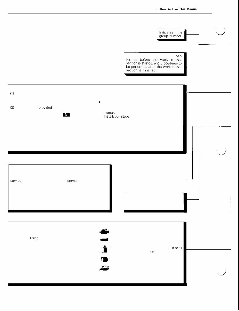
4 INTRODUCTION AND MASTER TROUBLESHOOTING - “0~ to “se this Manual EXPLANATION OF MANUAL CONTENTS Indicates procedures to be per- Maintenance and Servicing Procedures l Removal steps: (1) A diagram of the component parts is provided The part designation number corresponds to the near the front of each section in order to give the number in the illustration to indicate removal reader a better understanding of the installed steps. condition of component parts, 0 Disassembly steps: (2) The numbers provided within the diagram indicate The part designation number corresponds to the the sequence for maintenance and servicing number in the illustration to indicate disassembly procedures; the symbol m indicates a non- . ,ns$$&on steps: reusable part; the tightening torque is provided where applicable. Specified in case installation is impossible in reverse order of removal steps. Omitted if installation is possible in reverse order of removal steps. l Reassembly steps: Specified in case reassembly is impossible in reverse order of disassembly steps. Omitted if reassembly is possible in reverse order of dis- assembly steps. Classifications of Major Maintenance/Service Points When there are major points relative to maintenance and servicing procedures (such as essential maintenance and sewice points, maintenance and service standard values, information regarding the use of special tools, etc.), these are arranged together as major maintenance and service points and explained in detail. l *:lndicates that there are essential points for removal or disassembly. l a: Indicates that there are essential points for Installation or reassembly. c Indicates (by symbols) where lubri- cation is necessary. In this example, sealant is applied (where indicated) to the steering gear box. Symbols for Lubrication, Sealants and Adhesives Information concerning the locations for lubrication and for application of sealants and adhesives is & : Grease provided, by using symbols, in the diagram of compo- nent parts or on the page following the component 4 : Sealant or adhesive parts page, and explained. I : Brake fluid, automatic transmission conditioner compressor oil :a : Engine oil or gear oil : Adhesive tape or butyl rubber tape
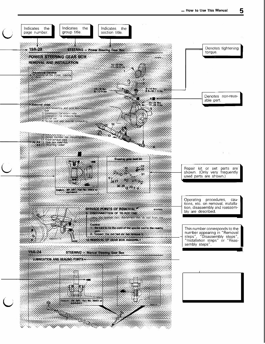
c INTRODUCTION AND MASTER TROUBLESHOOTING - “0~ to “se This Manua’ 5 This number corresponds to the ~~1 1 I The title of the page (following the page on which the diagram of component parts is pre- sented) indicating the locations of lubrication and sealing proce- dures.
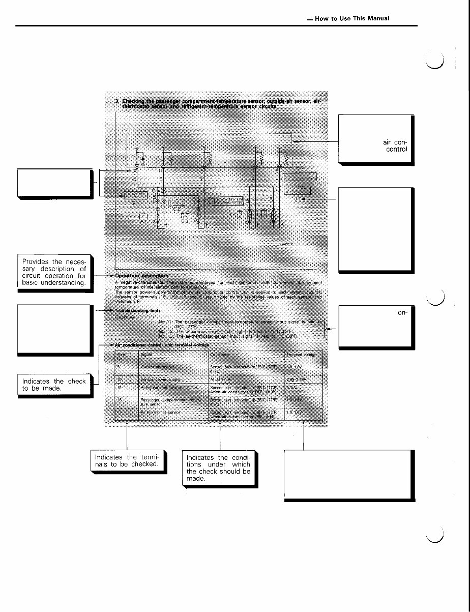
6 INTRODUCTION AND MASTER TROUBLESHOOTING - How to Use This Manual EXPLANATION OF THE TROUBLESHOOTING GUIDE I Indicates connec- tor’s terminal num- ber. t Provides hints (in- cluding standards for judgement) when troubleshooting pro- cedures are fol- lowed. Indicates the circuit diagram for checking (including the inter- face of the ato;Foi ditioning unit). Indicates the con- nector number. Numbers are used in the operation de- scriptions only as necessary, and these numbers correspond to the numbers used in harness and com- ponent layout dia- grams. Indicates the on- board diagnostic out- put code No. and the system conditions during output. Indicates the specification to be used for judgement of the check results. If there is no particular mention of conditions in the “Conditions” column, the column shows the specification under normal conditions.
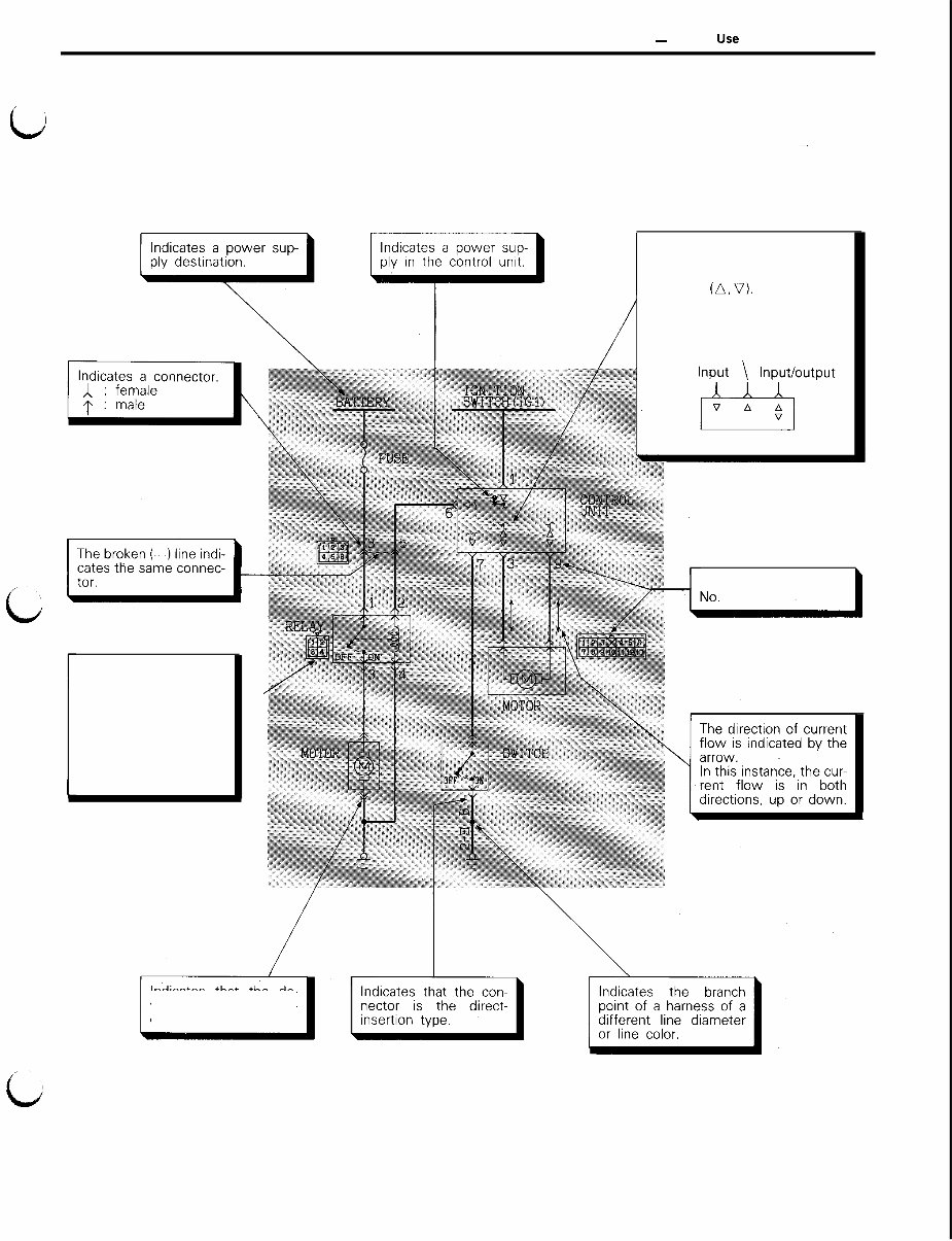
INTRODUCTION AND MASTER TROUBLESHOOTING - How to Use This Manual EXPLANATION OF CIRCUIT DIAGRAMS 7 b The symbols used in circuit diagrams are used as NOTE described below. For detailed information concerning the reading of circuit diagrams, refer to GROUP 8 - Wiring Harness. The input/output (direction of cur- rent flow) relative to the electro- nic control unit is indicated by symbols (A, V). The (A) symbol indicates that current flows in the upward direction. Output The connector symbol indicates the device side connector (for an intermediate connector, the male side connec- tor) as seen from the terminal front (the con- nector’s connection face). Indicates that the de- vice side connector in- cludes the harness. Indicates the terminal
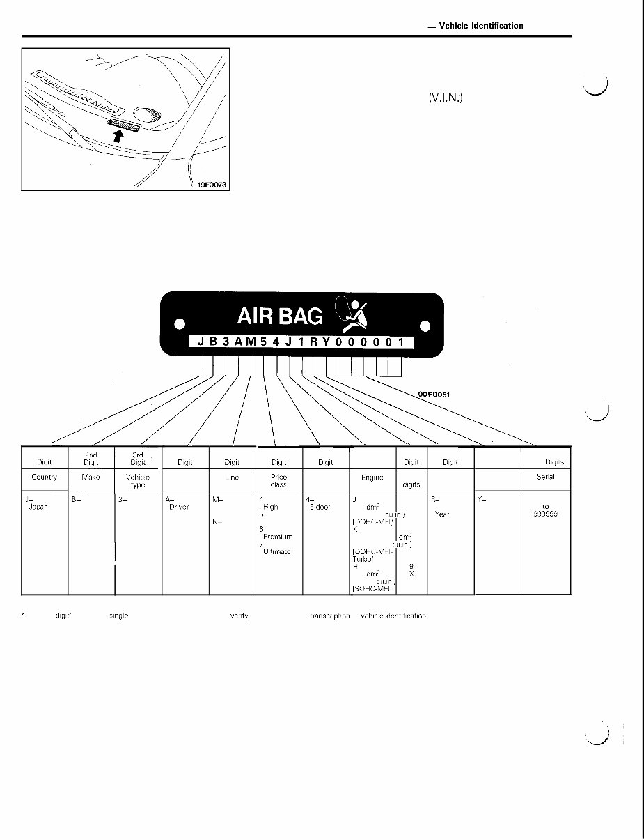
8 INTRODUCTION AND MASTER TROUBLESHOOTING - Vehicle Identification VEHICLE IDENTIFICATION VEHICLE IDENTIFICATION NUMBER LOCATION The vehicle identification number (V.I.N.) is located on a plate d attached to the left top side of the instrument panel. VEHICLE IDENTIFICATION CODE CHART PLATE All vehicle identification numbers contain 17 digits. The vehicle number is a code which tells country, make, vehicle type, etc. 1st DIgIt B- Dodge 3- Passenger Car / 4th DIgIt I 5th Digit Others Line A- Driver and Passenger Air Bag M- Stealth FWD N- Stealth AWD 6th DIgIt Price CIXS 4 High 5- sports 6- Premium 7- Ultimate 7th Digit Body 4- 3-door Hatchback \ . 8th 9th 10th Digit DIgIt DIgIt Engine *Check Model diglts year J- 1 R- 3.0 dm3 2 1994 (181 4 cu.,“) 3 Year lEoHC-MFI’ 3 . 0 dm3 (181.4 cu.~“.) [DOHC-MFI- Turbo] HP 3.0 dm3 ; (181.4 cun.) [SOHC-MFII 11th Digit Plant 12th to 17th Digits Serial number Y- Nagoya-l Plant 000001 99&99 * “Check dlglt” means a single number or letter X used to verify the accuracy of transcrlptlon of vehicle ldentiflcatlon number.
The 1991 Dodge Stealth OEM Service & Repair Manual is a detailed factory guide tailored for all trims of the first-year Stealth, including the SOHC, DOHC, and twin-turbocharged variants of the 3.0L 6G72 V6. Whether you're wrenching on the base model or dialing in boost on the top trim, this manual lays out everything you need in a clear, no-nonsense format.
It covers everything from engine teardown and torque specs to suspension, cooling, clutch, and driveline work. You'll find step-by-step transaxle rebuilds, brake system procedures (including ABS), and solid guides for fuel system diagnostics, emission testing, and even HVAC service. Diagrams and flowcharts are structured to walk you through each system without guesswork.
Content overview:
Master troubleshooting procedures and diagnostic flowcharts
Lubrication and maintenance intervals for all major systems
Complete front and rear suspension service guides
Rear axle disassembly and repair instructions
Brake system and parking brake servicing, including ABS
Detailed clutch removal, inspection, and reassembly steps
Cooling system diagnostics, radiator, and water pump info
In-depth engine repair procedures with torque specs
Intake and exhaust manifold servicing
Fuel system diagnostics, including injectors and fuel pump
Driveshaft and universal joint inspection procedures
Rear suspension component breakdown and torque sequences
Steering system adjustment and servicing
Manual and automatic transaxle disassembly and rebuild
Wheel and tire fitment, specs, and replacement
Bodywork, trim, and supplemental restraint system (SRS) instructions
HVAC system diagnostics and air conditioning repair
Emission control system testing and repair
Ideal for technicians and DIYers, this manual speaks your language. If you're keeping your ‘91 Stealth sharp or bringing one back to life, this is the kind of reference you'd want by your side in the garage.
Printable: Yes Language: English Compatibility: Pretty much any electronic device, incl. PC & Mac computers, Android and Apple smartphones & tablet, etc. Requirements: Adobe Reader (free)