FOREWORD The information contained in this service manual has been prepared for the professional automotive tech- nician involved in daily repair operations. This manual does not cover theory of operation, which is addressed in service training material. Information describing the operation and use of standard and optional equipment is included in the Owner's Manual provided with the vehicle. Information in this manual is divided into groups. These groups contain general information, diagnosis, testing, adjustments, removal, installation, disassembly, and assembly procedures for the components. The Component and System Index of this manual identifies the correct group for the component or system to be serviced. In addition, a Service Manual Comment form is included at the rear of this manual. Use the form to provide Chrysler Corporation with your comments and suggestions. To assist in locating a group title page, use the Group Tab Locator on the following page. The solid bar after the group title is aligned to a solid tab on the first page of each group. The first page of the group has a contents section that lists major topics within the group. Tightening torques are provided as a specific value throughout this manual. This value represents the midpoint of the acceptable engineering torque range for a given fastener application. These torque values are intended for use in service assembly and installation procedures using the correct OEM fasteners. When re- placing fasteners, always use the same type (part number) fastener as removed. Chrysler Corporation reserves the right to change testing procedures, specifications, diagnosis, repair methods, or vehicle wiring at any time without prior notice or incurring obligation. NOTE: The acronyms, terminology and nomenclature used to identify emissions related components in this manual may have changed from prior publications. These new terms are in compliance with S.A.E. recommended practice J1930. This terminology standard (J1930) is required to comply with the 1993 California Air Research Board (CARB) requirements.
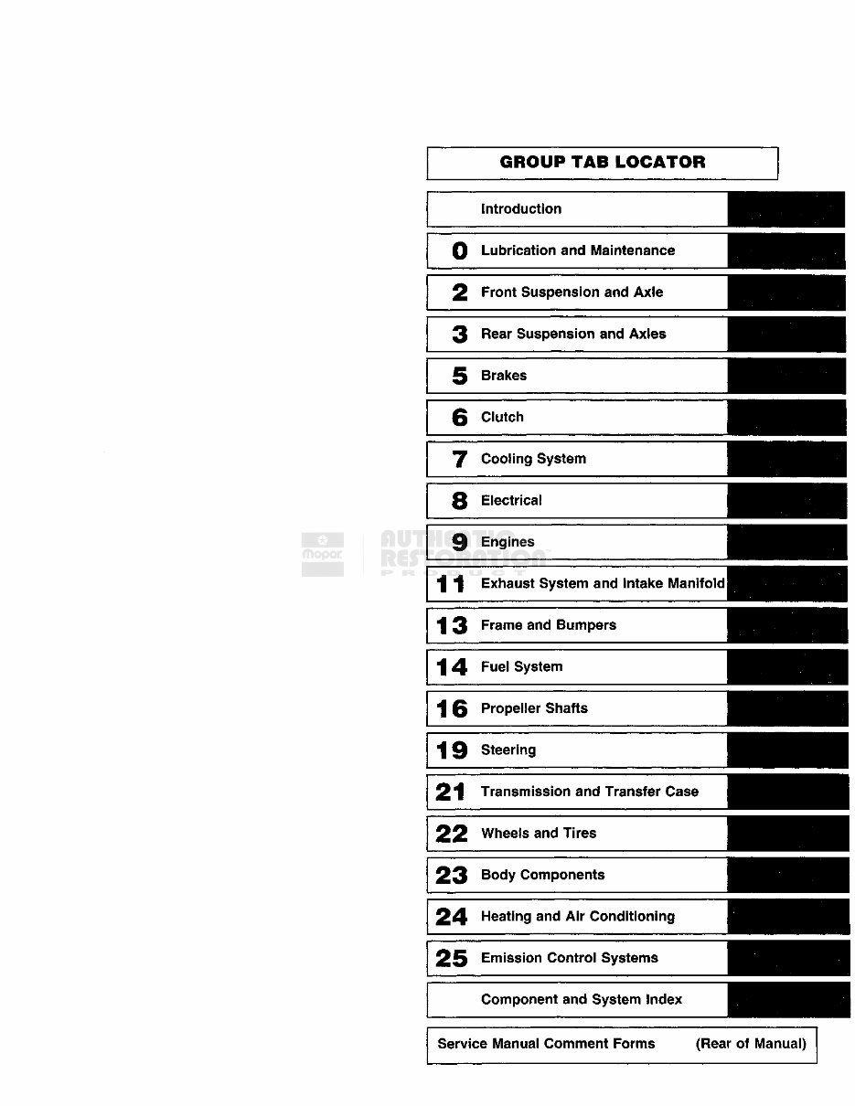
GROUP TAB LOCATOR Introduction 0 Lubrication and Maintenance 2 Front Suspension and Axle 3 Rear Suspension and Axles 5 Brakes 6 Clutch 7 Cooling System 8 Electrical 9 Engines 11 Exhaust System and Intake Manifold 1 3 F r a m e and Bumpers 14 F u e l System 1 6 Propeller Shafts 19 Steering 21 Transmission and Transfer Case 22 Wheels and Tires 23 B o d y Components 24 Heating and Air Conditioning 25 Emission Control Systems Component and System Index Service Manual Comment Forms (Rear of Manual)
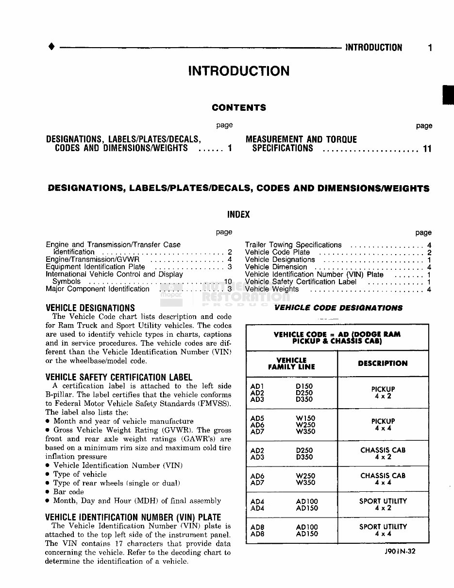
INTRODUCTION INTRODUCTION DESIGNATIONS, LABELS/PLATES/DECALS, CODES AND DIMENSIONS/WEIGHTS . CONTENTS page MEASUREMENT AND TORQUE . . . 1 SPECIFICATIONS page . 11 DESIGNATIONS, LABELS/PLATES/DECALS, CODES AND DIMENSIONS/WEIGHTS INDEX page Engine and Transmission/Transfer Case Identification 2 Engine/Transmission/GVWR 4 Equipment Identification Plate 3 International Vehicle Control and Display Symbols 10 Major Component Identification 3 VEHICLE DESIGNATIONS The Vehicle Code chart lists description and code for Ram Truck and Sport Utility vehicles. The codes are used to identify vehicle types in charts, captions and in service procedures. The vehicle codes are dif- ferent than the Vehicle Identification Number (VIN) or the wheelbase/model code. VEHICLE SAFETY CERTIFICATION LABEL A certification label is attached to the left side B-pillar. The label certifies that the vehicle conforms to Federal Motor Vehicle Safety Standards (FMVSS). The label also lists the: • Month and year of vehicle manufacture • Gross Vehicle Weight Rating (GVWR). The gross front and rear axle weight ratings (GAWR's) are based on a minimum rim size and maximum cold tire inflation pressure Vehicle Identification Number (VIN) Type of vehicle Type of rear wheels (single or dual) Bar code Month, Day and Hour (MDH) of final assembly VEHICLE IDENTIFICATION NUMBER (VIN) PLATE The Vehicle Identification Number (VIN) plate is attached to the top left side of the instrument panel. The VIN contains 17 characters that provide data concerning the vehicle. Refer to the decoding chart to determine the identification of a vehicle. page Trailer Towing Specifications 4 Vehicle Code Plate 2 Vehicle Designations 1 Vehicle Dimension 4 Vehicle Identification Number (VIN) Plate 1 Vehicle Safety Certification Label ............. 1 Vehicle Weights 4 VEHICLE CODE DESIGNATIONS VEHICLE CODE = A D (DODGE RAM PICKUP & CHASSIS CAB) VEHICLE FAMILY LINE DESCRIPTION AD1 D150 AD2 D250 AD3 D350 PICKUP 4x2 AD5 W150 AD6 W250 AD7 W350 PICKUP 4x4 AD2 D250 AD3 D350 CHASSIS CAB 4x2 AD6 W250 AD7 W350 CHASSIS CAB 4x4 AD4 AD100 AD4 AD150 SPORT UTILITY 4x2 AD8 AD100 AD8 AD 150 SPORT UTILITY 4x4 J90IN-32
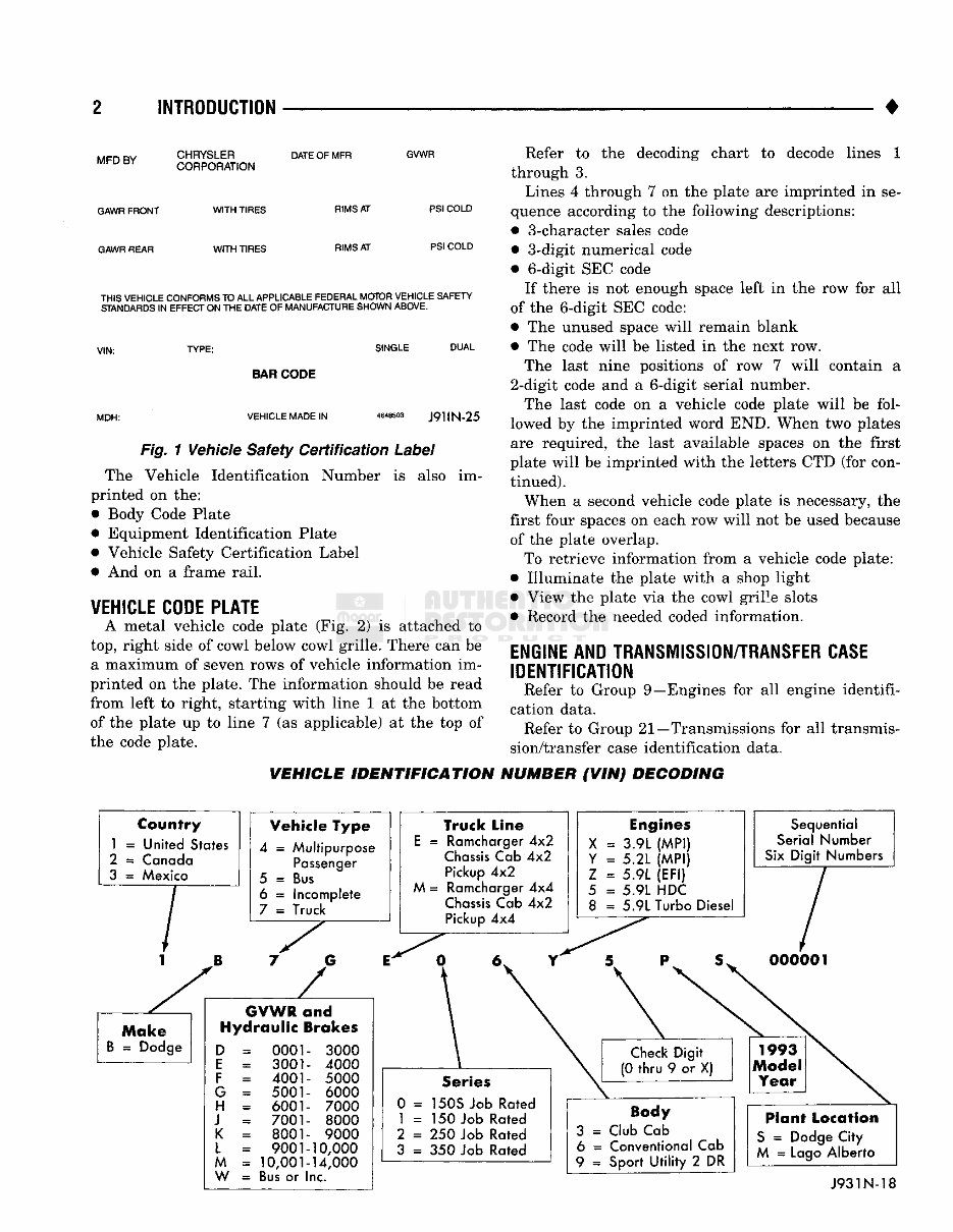
2 INTRODUCTION • MFD BY GAWR FRONT GAWR REAR CHRYSLER CORPORATION DATE OF MFR GVWR WITH TIRES WITH TIRES RIMS AT RIMS AT PSI COLD PSI COLD THIS VEHICLE CONFORMS TO ALL APPLICABLE FEDERAL MOTOR VEHICLE SAFETY STANDARDS IN EFFECT ON THE DATE OF MANUFACTURE SHOWN ABOVE. SINGLE DUAL MDH: BAR CODE VEHICLE MADE IN 4648503 J9HN-25 Fig. 1 Vehicle Safety Certification Label The Vehicle Identification Number is also im- printed on the: • Body Code Plate • Equipment Identification Plate • Vehicle Safety Certification Label • And on a frame rail. VEHICLE CODE PLATE A metal vehicle code plate (Fig. 2) is attached to top, right side of cowl below cowl grille. There can be a maximum of seven rows of vehicle information im- printed on the plate. The information should be read from left to right, starting with line 1 at the bottom of the plate up to line 7 (as applicable) at the top of the code plate. Refer to the decoding chart to decode lines 1 through 3. Lines 4 through 7 on the plate are imprinted in se- quence according to the following descriptions: • 3-character sales code • 3-digit numerical code • 6-digit SEC code If there is not enough space left in the row for all of the 6-digit SEC code: • The unused space will remain blank • The code will be listed in the next row. The last nine positions of row 7 will contain a 2-digit code and a 6-digit serial number. The last code on a vehicle code plate will be fol- lowed by the imprinted word END. When two plates are required, the last available spaces on the first plate will be imprinted with the letters CTD (for con- tinued). When a second vehicle code plate is necessary, the first four spaces on each row will not be used because of the plate overlap. To retrieve information from a vehicle code plate: • Illuminate the plate with a shop light • View the plate via the cowl grille slots • Record the needed coded information. ENGINE AND TRANSMISSION/TRANSFER CASE IDENTIFICATION Refer to Group 9—Engines for all engine identifi- cation data. Refer to Group 21—Transmissions for all transmis- sion/transfer case identification data. VEHICLE IDENTIFICATION NUMBER (VIN) DECODING Country 1 = United States 2 = Canada 3 = Mexico Vehicle Type 4 = Multipurpose Passenger 5 = Bus 6 = Incomplete 7 = Truck GVWR and Hydraulic Brakes 0001 3001 4001 5001 6001 7001 8001 9001 10,001 Bus or I 3000 4000 5000 6000 7000 8000 9000 10,000 14,000 nc. Truck Line E = Ramcharger 4x2 Chassis Cab 4x2 Pickup 4x2 M = Ramcharger 4x4 Chassis Cab 4x2 Pickup 4x4 Engines X = 3.9L (MPI) Y = 5.2L (MPI) Z = 5.9L (EFI) 5 = 5.9L HDC 8 = 5.9L Turbo Diesel Sequential Serial Number Six Digit Numbers Series 0 = 150S Job Rated 1 = 150 Job Rated 2 = 250 Job Rated 3 = 350 Job Rated Body 3 = Club Cab 6 = Conventional Cab 9 = Sport Utility 2 DR Plant Location S = Dodge City M = Lago Alberto J931N-18
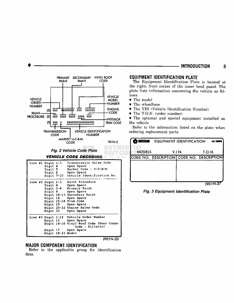
INTRODUCTION PRIMARY SECONDARY PAINT PAINT VINYL ROOF CODE VEHICLE ORDER- NUMBER PAINT- PI PROCEDURE (2) (1) XXX ) XXXXX) X XXX xxxxxx X )0C xxxx xxxx xxxx xxx XXX x xxxxxxxxxxxxxxxxx TRANSMISSION I VEHICLE IDENTIFICATION CODE J NUMBER MARKET U-C-B-M CODE 90IN-3 Fig. 2 Vehicle Code Plate VEHICLE CODE DECODING VEHICLE MODEL •NUMBER ENGINE -CODE -INTERIOR TRIM CODE Line #1 Digit 1-3 Transmission Sales Code Digit 4 Open Space Digit 5 Market Code - U-C-B-M Digit 6 Open Space Digit 7-23 Vehicle Identification No. Line #2 Digit 1-3 Paint Procedure Digit 4 Open Space Digit 5-8 Primary Paint Digit 9 Open Space Digit 10-13 Secondary Paint Digit 14 Open Space Digit 15-18 Trim Code Digit 19 Open Space Digit 20-22 Engine Sales Code Digit 23 Open Space Line #3 Digit 1-12 Vehicle Order Number Digit 13 Open Space Digit 14-16 Vinyl Roof Code (Door Combo Digit Code - Pillette) Digit 17 Open Space Digit 18-23 Model J901N-20 MAJOR COMPONENT IDENTIFICATION Refer to the applicable group for identification data. EQUIPMENT IDENTIFICATION PLATE The Equipment Identification Plate is located at the right, front corner of the inner hood panel. The plate lists information concerning the vehicle as fol- lows: The model The wheelbase The VIN (Vehicle Identification Number) The T.O.N, (order number) The optional and special equipment installed on the vehicle Refer to the information listed on the plate when ordering replacement parts. r § W l l EQUIPMENT IDENTIFICATION mmm MODELS V.I.N. T.O.N. CODE NO. DESCRIPTION CODE NO. DESCRIPTION . ^ Fig. 3 Equipment Identification Plate
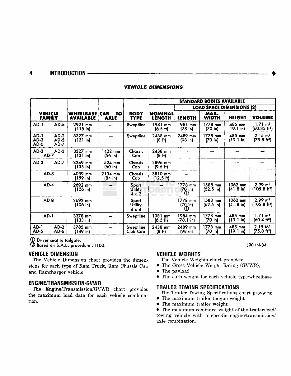
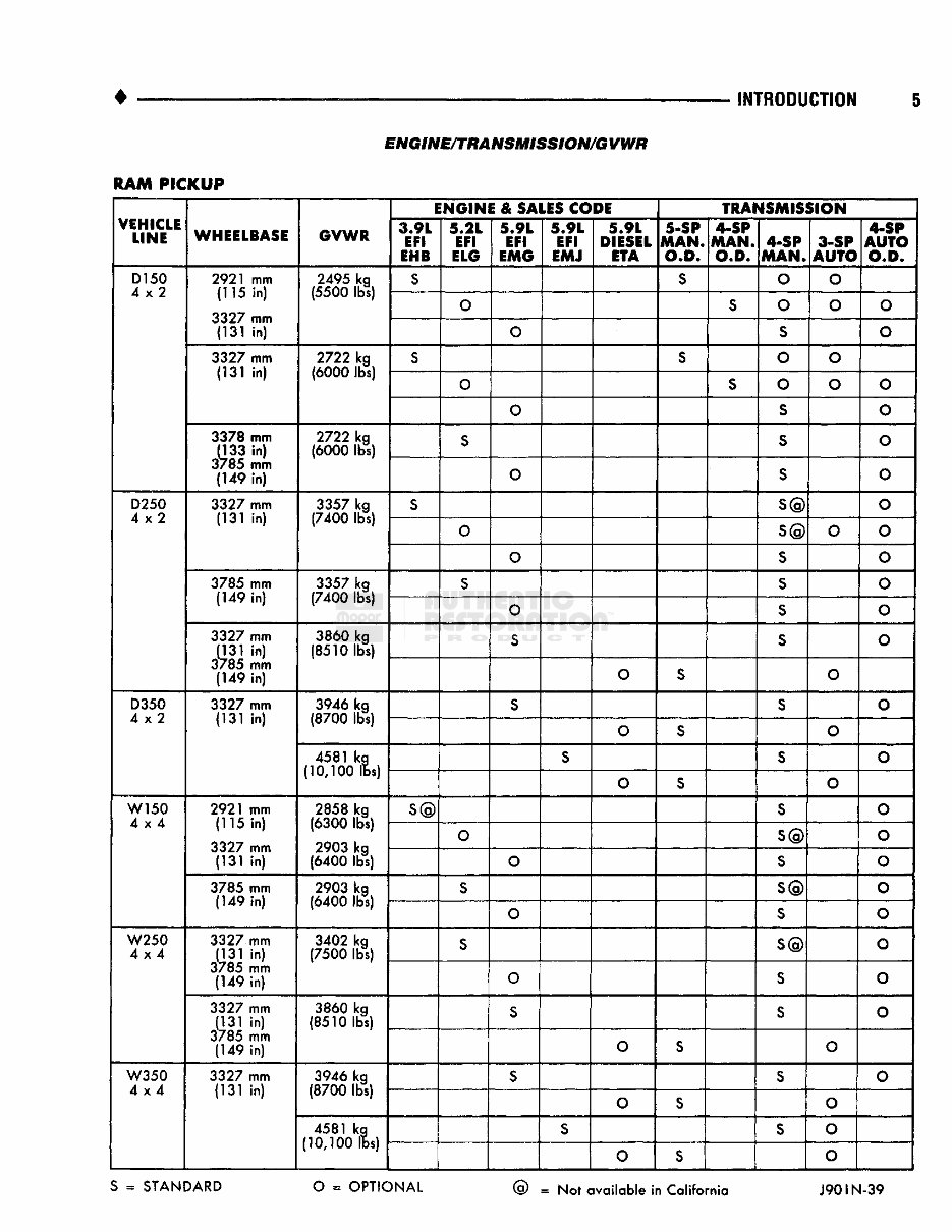
4 INTRODUCTION • VEHICLE DIMENSIONS VEHICLE FAMILY WHEELBASE AVAILABLE CAB TO AXLE BODY TYPE SfANDAID SODIES AVAILABLE VEHICLE FAMILY WHEELBASE AVAILABLE CAB TO AXLE BODY TYPE NOMINAL LENGTH (LOAD SPACE D MENSIONS (2) VEHICLE FAMILY WHEELBASE AVAILABLE CAB TO AXLE BODY TYPE NOMINAL LENGTH LENGTH MAX. WIDTH HEIGHT VOLUME AD-1 AD-5 2921 mm (115 in) — Sweptline 1981 mm (6.5 ft) 1981 mm (78 in) 1778 mm (70 in) 485 mm 19.1 in) 1.71 m 3 (60.35 ft 3 ) AD-1 AD-2 AD-3 AD-5 AD-6 AD-7 3327 mm (131 in) — Sweptline 2438 mm (8 ft) 2489 mm (98 in) 1778 mm (70 in) 485 mm (19.1 in) 2.15 m 3 (75.8 ft 3 ) AD-2 AD-3 AD-7 3327 mm (131 in) 1422 mm (56 in) Chassis Cab 2438 mm (8 ft) — — — — AD-3 AD-7 3249 mm (135 in) 1524 mm (60 in) Chassis Cab 2896 mm (9.5 ft) — — — — AD-3 4039 mm (159 in) 2134 mm (84 in) Chassis Cab 3810 mm (12.5 ft) — — — AD-4 2692 mm (106 in) Sport Utility 4x2 — 1778 mm 1588 mm (62.5 in) 1062 mm (41.8 in) 2.99 m 3 (105.8 ft 3 ) AD-8 2692 mm (106 in) Sport Utility 4x4 — 1778 mm 1588 mm (62.5 in) 1062 mm (41.8 in) 2.99 m 3 (105.8 ft 3 ) AD-1 3378 mm (133 in) — Sweptline 1981 mm (6.5 ft) 1984 mm (78.1 in) 1778 mm (70 in) 485 mm (19.1 in) 1.71 m 3 (60.4 ft 3 ) AD-1 AD-2 AD-5 AD-6 3785 mm (149 in) — Sweptline Club Cab 2438 mm (8 ft) 2489 mm (98 in) 1778 mm (70 in) 485 mm (19.1 in) 2.15 M 3 (75.8 ft 3 ) ® Driver seat to tailgate. (2) Based on S.A.E. procedure Jl 100. J901N-34 VEHICLE WEIGHTS The Vehicle Weights chart provides: • The Gross Vehicle Weight Rating (GVWR), • The payload • The curb weight for each vehicle type/wheelbase TRAILER TOWING SPECIFICATIONS The Trailer Towing Specifications chart provides: • The maximum trailer tongue weight • The maximum trailer weight • The maximum combined weight of the trailer/load/ towing vehicle with a specific engine/transmission/ axle combination. VEHICLE DIMENSION The Vehicle Dimension chart provides the dimen- sions for each type of Ram Truck, Ram Chassis Cab and Ramcharger vehicle. ENGINE/TRANSMISSION/GVWR The Engine/Transmission/GVWR chart provides the maximum load data for each vehicle combina- tion.
Owning a 1990 Dodge W350 comes with the need for a reliable repair manual. This comprehensive manual is designed to assist both professional mechanics and DIY enthusiasts in maintaining and repairing their vehicles. Unlike traditional paper manuals, this digital format offers convenience and cost-effectiveness.
Whether you are looking to address brake issues, replace suspension components, troubleshoot the engine, or perform standard maintenance, this manual provides all the necessary information. It covers a wide range of areas including brakes, engine, suspension, steering, drivetrain, electrical systems, heating, and air conditioning.
By utilizing this repair manual, you can save a significant amount of money on repairs that would otherwise be costly when handled by a professional mechanic. The manual is compatible with Windows, Mac computers, smartphones, and tablets, ensuring easy access for all users.