G - TESTS W/CODES - 3.9L Article Text (p. 2) 1996 Dodge R If PCM detects a cylinder(s) misfire, lean fuel condition or a rich fuel condition, MIL is immediately turned on. On manual transmission vehicles, MIL will either flash or light continuously during an active engine misfire. PCM will turn off MIL when malfunction is not detected during 3 run/stop cycles of engine of at least a 2 minute duration. MIL may be turned off by PCM, however, a DTC may remain stored depending on type of malfunction detected. On-Board Diagnostics The PCM monitors several different engine control system circuits. If malfunction occurs, PCM will store a DTC when malfunction is detected, and PCM will enter limp-in mode. In limp-mode, PCM substitutes values for failed component to continue engine operation, but loss of good driveability may result. The PCM contains electronic circuit monitors that monitor fuel, vehicle emissions, engine and ignition system performance. Monitors use information from various sensor circuits for system monitoring. Monitors do not indicate a specific component failure, but indicate an implied failure within a specified system, and that the problem must be diagnosed. If any monitor detects a problem affecting vehicle emissions, a DTC will be stored in PCM. The following monitors are used: * EGR Monitor * Engine Misfire Monitor * Fuel System Monitor * Oxygen Sensor Monitor * Oxygen Sensor Heater Monitor * Catalyst Monitor * EVAP System Leak Detection Monitor The PCM will erase DTC once MIL is turned off. Once MIL is turned off, PCM must not detect the recent malfunction during 40 run/stop engine cycles with engine coolant temperature at least 160 F (71 C) on normal operation, or 80 run/stop engine cycles with engine coolant temperature at least 160 F (71 C) on engine misfire or fuel system monitor. PCM also records and stores engine operating conditions when malfunction occurred. This information is referred to as freeze frame data. If malfunction is an engine misfire or fuel system rich or fuel system lean, freeze frame data will be updated with the most current information regarding these failures. Freeze frame data recorded is: * Fuel System Status * Load Value (Displayed As Percent) * Long Term Adaptive (Displayed As Percent) * Short Term Adaptive (Displayed As Percent) * Absolute MAP (Displayed As Percent) * Engine RPM * Vehicle Speed Sensor * DTC During Data Recording
G - TESTS W/CODES - 3.9L Article Text (p. 3) 1996 Dodge Ram Van B2500F DTCs may be retrieved for system diagnosis by using scan tool and MIL. See RETRIEVING DTCS under SELF-DIAGNOSTIC SYSTEM. By using scan tool and MIL, self-diagnostic capabilities of this system can simplify testing and reduce diagnostic time. System malfunctions are identified as either hard failures or intermittent failures. Hard Failures Hard failures cause MIL to illuminate and remain on until problem is repaired. If MIL comes on and remains on during vehicle operation, cause of malfunction must be determined by retrieving DTCs. See RETRIEVING DTCS under SELF-DIAGNOSTIC SYSTEM. If a sensor fails, PCM will use substitute value in its calculations to continue engine operation. In this condition, commonly known as limp-in mode, the vehicle runs but driveability will not be optimum. Intermittent Failures Intermittent failures may cause MIL to flicker or illuminate and go out after intermittent failure goes away. However, the corresponding DTC will be retained in PCM memory. If related failure does not reoccur within a certain time frame, related DTC will be erased from PCM memory. Intermittent failures may be caused by a sensor, connector or wiring related problems. See INTERMITTENTS in the H - TESTS W/O CODES - 3.9L article. SELF-DIAGNOSTIC SYSTEM SERVICE PRECAUTIONS Before proceeding with system diagnosis, following precautions must be followed: * Ensure fuel pressure is released before removing fuel line or fittings, as fuel system is under pressure and may cause personal injury. See FUEL PRESSURE RELEASE procedure. * When performing self-diagnostic tests, DO NOT skip any steps, or incorrect diagnosis may result. Always perform indicated verification procedure after each repair. * When using a jumper wire, ensure either jumper wire or circuit is fuse-protected. * Before disconnecting connector from any control module, ensure ignition is off before removing connector. * When checking voltage or continuity at any control module, DO NOT backprobe connector (unless instructed to do otherwise in test procedure), or probe wires through the insulation. * DO NOT cause short circuits when performing electrical tests. This will set additional DTCs, making diagnosis of original problem more difficult. * Use test equipment specified in test procedures when performing electrical tests. * When checking for spark, ensure cable is NOT more than 1/4" from engine ground. If cable is more than 1/4" from engine
G - TESTS W/CODES - 3.9L Article Text (p. 4) ground, damage to vehicle electronics and/or PCM may result. * DO NOT prolong testing of fuel injectors or engine may hydrostatically lock. DIAGNOSTIC PROCEDURE If no faults were found while performing procedures in the F - BASIC TESTING - 3.9L article, proceed with self-diagnostics. Always perform a visual inspection before attempting to diagnose engine control system problems. See VISUAL INSPECTION. Retrieve DTCs using MIL and scan tool. See RETRIEVING DTCS. VISUAL INSPECTION Most driveability problems in the engine control system result from faulty wiring, poor electrical connections, improper wire routing, or leaking air and vacuum hose connections. Inspect all engine control system components, hoses, connectors and wiring for damage before proceeding with system testing. RETRIEVING DTCS NOTE: It will be necessary to use MIL and scan tool to retrieve all DTCs. When using MIL to retrieve DTCs, some DTCs have more than one meaning. The MIL is unable to distinguish between different failures for a specified component. For example, there are several possible failures for the downstream oxygen sensor system, but the MIL can only identify a downstream oxygen sensor failure by flashing a DTC 21, but the scan tool will be able to distinguish between the different failures. When using scan tool, scan tool is not able to identify all possible DTCs. As an example, scan tool may not be able to identify or display a DTC for a malfunctioning A/C clutch relay circuit, Auto Shutdown (ASD) relay circuit, or charging system voltage circuit, but these DTCs will be displayed by the MIL. Using Malfunction Indicator Light (MIL) 1) Ensure battery is fully charged. Turn ignition on and note operation of MIL. When ignition is first turned on, MIL should come on and remain on for 3 seconds to verify bulb and circuit operation, and then go off. NOTE: If MIL does not come on for 3 seconds and then go off, bulb circuit may be defective, or problem area may exist on CCD Bus between PCM and instrument cluster. If problem exists with CCD Bus, this problem may be displayed when using scan tool to retrieve DTCs. 2) Attempt to start engine. Turn ignition off. Without starting engine, turn ignition on, off, on, off and on within 5 seconds. Record 2-digit DTCs as displayed by flashing MIL.
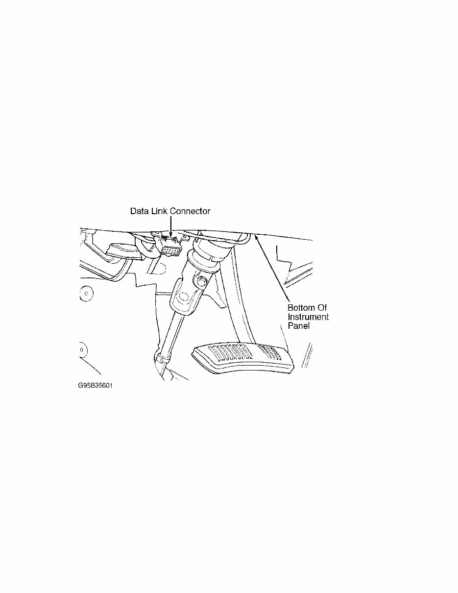
G - TESTS W/CODES - 3.9L Article Text (p. 5) 1996 3) For example, DTC 24 will be displayed by 2 flashes, short pause, and then 4 more flashes. A short pause will exist between first and second digits on DTC. If more than one DTC is stored, after first DTC is displayed, there will be a longer pause and then another stored DTC will be displayed. 4) Once all DTCs are recorded, retrieve DTCs using scan tool to ensure all DTCs are obtained. See USING SCAN TOOL. Using Scan Tool 1) Ensure battery is fully charged. Attempt to start engine. Turn ignition off. Connect scan tool to Data Link Connector (DLC). DLC is located below instrument panel near steering column. See Fig. 1. Fig. 1: Locating Data Link Connector (Typical) Courtesy of Chrysler Corp. 2) Turn ignition on. Using scan tool manufacturer's instructions, record all DTCs displayed on scan tool. Using all DTCs obtained, proceed to SELF-DIAGNOSTIC TESTS. Once all repairs are made, ensure DTCs are cleared from PCM memory. See CLEARING DTCS. CLEARING DTCS Ensure ignition is off, then turn ignition on. Using scan tool manufacturer's instructions, erase DTCs from PCM memory. INACTIVE DTC CONDITION This procedure applies if you have been sent here from diagnostic tests and have just attempted to simulate the condition that initially set the DTC. The following additional checks may assist in identifying a possible intermittent problem:
G - TESTS W/CODES - 3.9L Article Text (p. 6) 1996 Dodge Ram V * Visually inspect related wiring harness connectors for broken, bent, pushed out or corroded terminals. * Visually inspect related wiring harnesses for chafed, pierced or partially broken wires. * Check for pertinent Technical Service Bulletins (TSBs) relating to the problem. FUEL PRESSURE RELEASE WARNING: Fuel system is under high pressure. ALWAYS release fuel pressure before attempting to open system for testing or component replacement. DO NOT allow fuel to flow onto engine or electrical parts while testing fuel system components. FUEL PRESSURE RELEASE Vehicles With Fuel Rail Test Port 1) Loosen fuel tank filler cap. Ensure ignition is off. Remove protective cap from fuel rail test port. 2) Place one end of Fuel Pressure Release Hose (C-4799-1) into an approved fuel container. Attach remaining end of hose to fuel rail test port. Use care, as fuel system may be under pressure. Fuel pressure will be released from fuel system. Remove hose, reinstall protective cap, and fuel tank filler cap. 3) Wait 5 seconds. Use care when disconnecting fuel lines, as some fuel pressure may still exist in fuel lines. NOTE: One or more DTCs may set when fuel pump relay is removed. Clear DTCs after fuel pressure release procedure. See CLEARING DTCS under SELF-DIAGNOSTIC SYSTEM. Vehicles Without Fuel Rail Test Port 1) Remove fuel pump relay from Power Distribution Center (PDC). Relays are identified on label under PDC cover. Start and run engine until it stalls. Attempt to start engine. Continue restarting engine until it will no longer run. Turn ignition off. CAUTION: DO NOT supply power to fuel injector for more than 4 seconds, or fuel injector may be damaged. 2) Disconnect any fuel injector connector. Connect a jumper wire between either fuel injector terminal and positive battery terminal. Connect another jumper wire to other fuel injector terminal. Momentarily touch other end of jumper wire to negative battery terminal. 3) Place a shop towel under fuel line quick-connector at fuel rail. Use care when disconnecting fuel lines, as some fuel pressure may still exist in fuel lines. Disconnect fuel line quick-connector. Reinstall fuel pump relay in PDC. Clear DTCs. See CLEARING DTCS under SELF-DIAGNOSTIC SYSTEM.
The 1996 Dodge Ram Van B2500 Service & Repair Manual is the official factory manual for servicing the full-size B2500 van platform equipped with 3.9L, 5.2L (gas and CNG), and 5.9L engines. This manual is designed for dealership technicians and experienced mechanics, covering both routine service and complete overhauls with model-specific procedures, diagnostic guides, and wiring diagrams.
Every major system is broken down with theory, adjustments, troubleshooting charts, electrical component locations, and exploded diagrams. From air conditioning and fuel systems to suspension geometry and emissions controls, each section is tailored to the 1996 model year and its supported powertrains. This manual also includes component testing procedures and vacuum routing for all covered engine types.
Content Overview:
Complete engine mechanical, overhaul, and operation theory (3.9L, 5.2L, 5.9L)
Fuel systems: Gasoline and CNG diagnostics, component testing, and wiring
AC & heating system troubleshooting and servicing procedures
Electrical system inspection, diagnostics, and wiring diagram guides
Brake systems including anti-lock rear-wheel specifics and uniform inspection procedures
Front and rear suspension diagrams, alignment specs, and theory
Transmission removal, servicing (automatic & manual), and oil pan gasket ID
Exhaust system specifications and general overhaul procedures
Body electrical: Wipers, defogger, mirrors, lights, locks, horn, and power windows
Wiring diagrams and vacuum schematics per engine variant
Airbag and passive restraint inspection
General service information, scheduled maintenance, and metric conversion charts
This manual is the most complete factory-level guide available for working on the 1996 Ram B2500 van. Whether you're restoring a van, servicing fleet vehicles, or diagnosing wiring faults, this manual equips you with all the technical detail needed to do the job right.
Printable: Yes Language: English Compatibility: Pretty much any electronic device, incl. PC & Mac computers, Android and Apple smartphones & tablet, etc. Requirements: Adobe Reader (free)