2023 RAM 3500 Cab Chasis 6.4L V8 Heavy Duty Hemi MDS Service & Repair Manual
What's Included?
Lifetime Access
Fast Download Speeds
Online & Offline Access
Access PDF Contents & Bookmarks
Full Search Facility
Print one or all pages of your manual
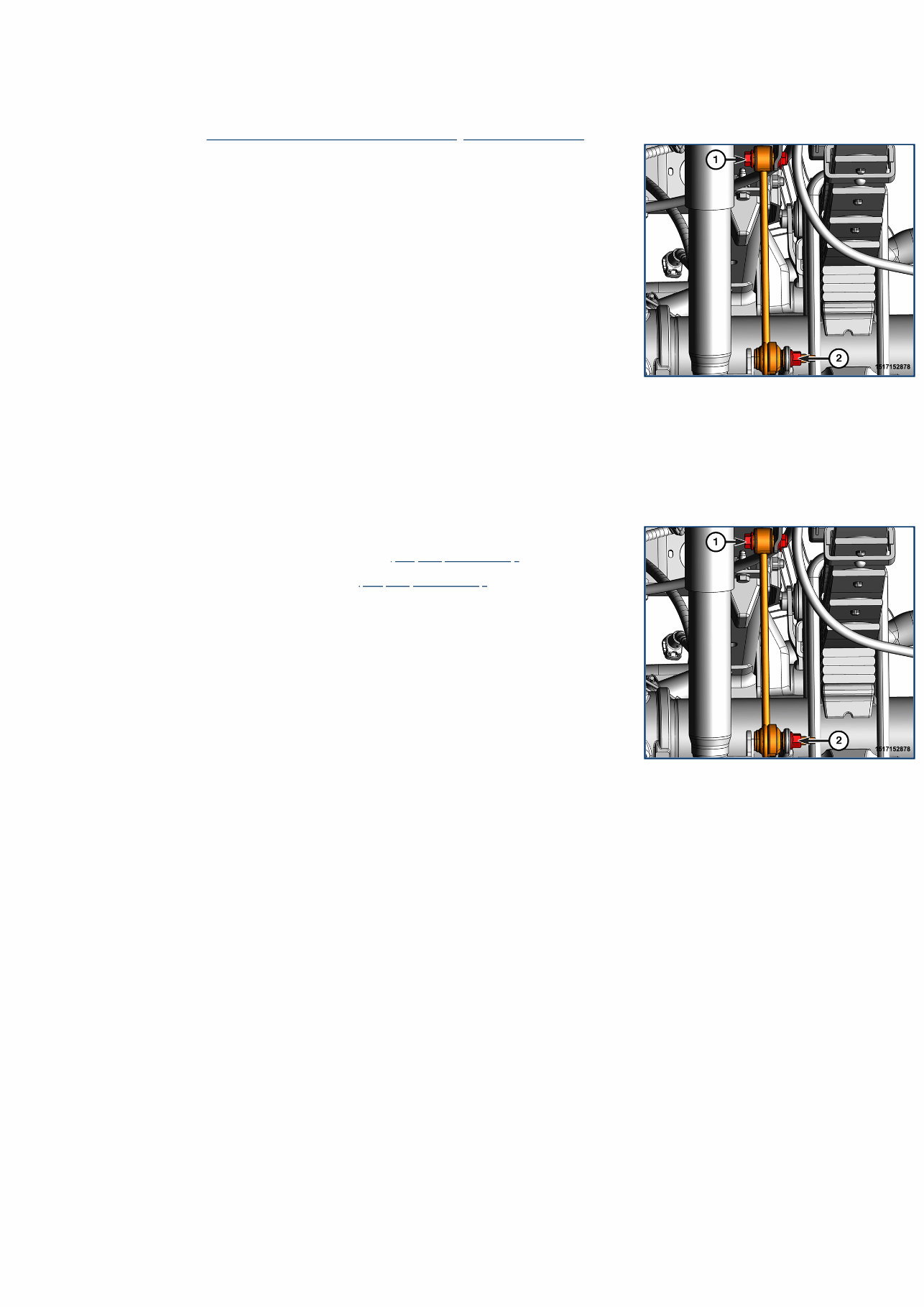
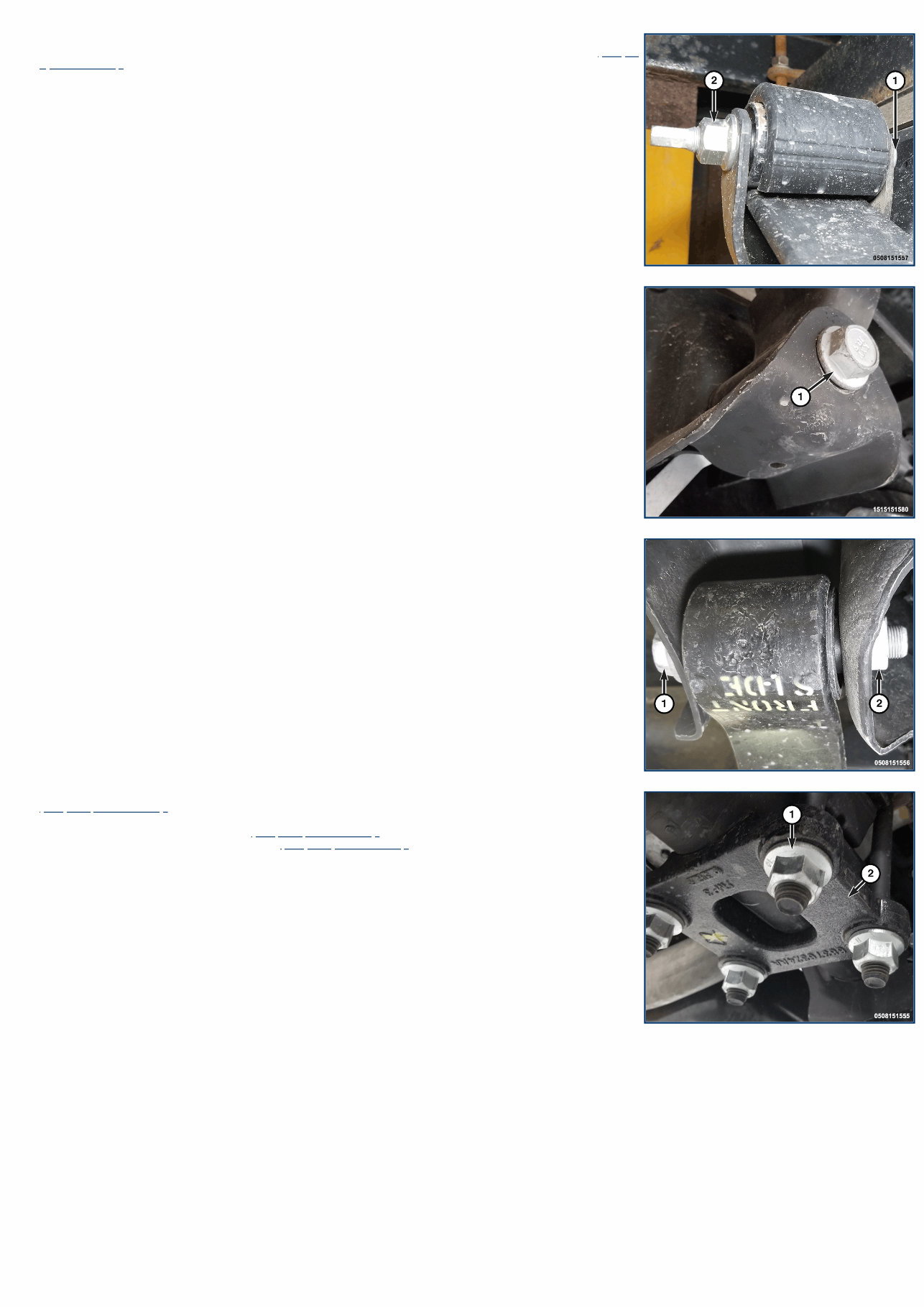
17 - Rear Suspension / LINK, Stabilizer Bar / Removal and Installation REMOVAL AND INSTALLATION REMOVAL 1. Raise and support the vehicle (Refer to 04 - Vehicle Quick Reference/Hoisting/Standard Procedure) . 2. Remove the stabilizer bar link upper bolt (1) and nut. 3. Remove the stabilizer bar link lower nut (2). 4. Remove the stabilizer bar link. INSTALLATION NOTE: In any instance where a bolt is through a rubber bushing, the bolt must be torqued with the vehicle at normal ride height. 1. Install the stabilizer link and install the stabilizer bar link upper bolt (1) and nut. Do not tighten. 2. Install the stabilizer link lower nut (2) and tighten to the proper (Torque Specifications) . 3. Remove the support and lower the vehicle. 4. Tighten the stabilizer bar link upper bolt (1) to the proper (Torque Specifications) .
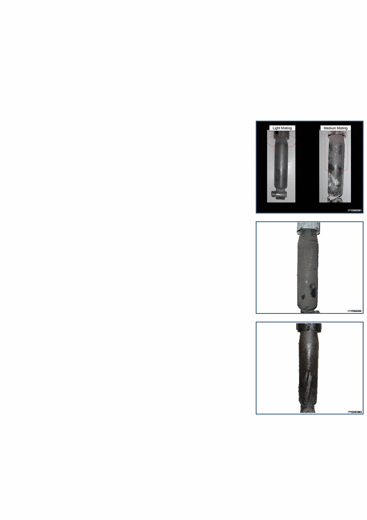
17 - Rear Suspension / SHOCK ABSORBER, Suspension / Diagnosis and Testing DIAGNOSIS AND TESTING - SHOCK ABSORBER A knocking or rattling noise from a shock absorber may be caused by movement between mounting bushings and metal brackets or attaching components. These noises can usually be stopped by tightening the attaching nuts. If the noise persists, inspect for damaged and worn bushings, and attaching components. Repair as necessary if any of these conditions exist. A squeaking noise from the shock absorber may be caused by the hydraulic valving and may be intermittent. This condition is not repairable and the shock absorber must be replaced. The shock absorbers are not refillable or adjustable. If a malfunction occurs, the shock absorber must be replaced. To test a shock absorber, hold it in an upright position and force the piston in and out of the cylinder four or five times. The action throughout each stroke should be smooth and even. This procedure does not apply to load leveling shocks. The shock absorber bushings do not require any type of lubrication. Do not attempt to stop bushing noise by lubricating them. Grease and mineral oil-base lubricants will deteriorate the bushing. When checking the rear shock absorbers visual condition it should be noted that slight oil dampness or “misting” does not indicate the unit has failed. Below are examples of misting shocks and a failed leaking shock: LIGHT and MEDIUM MISTING SHOCKS (DO NOT REPLACE) HEAVY MISTING SHOCK (DO NOT REPLACE) FAILED LEAKING SHOCK (REPLACE)
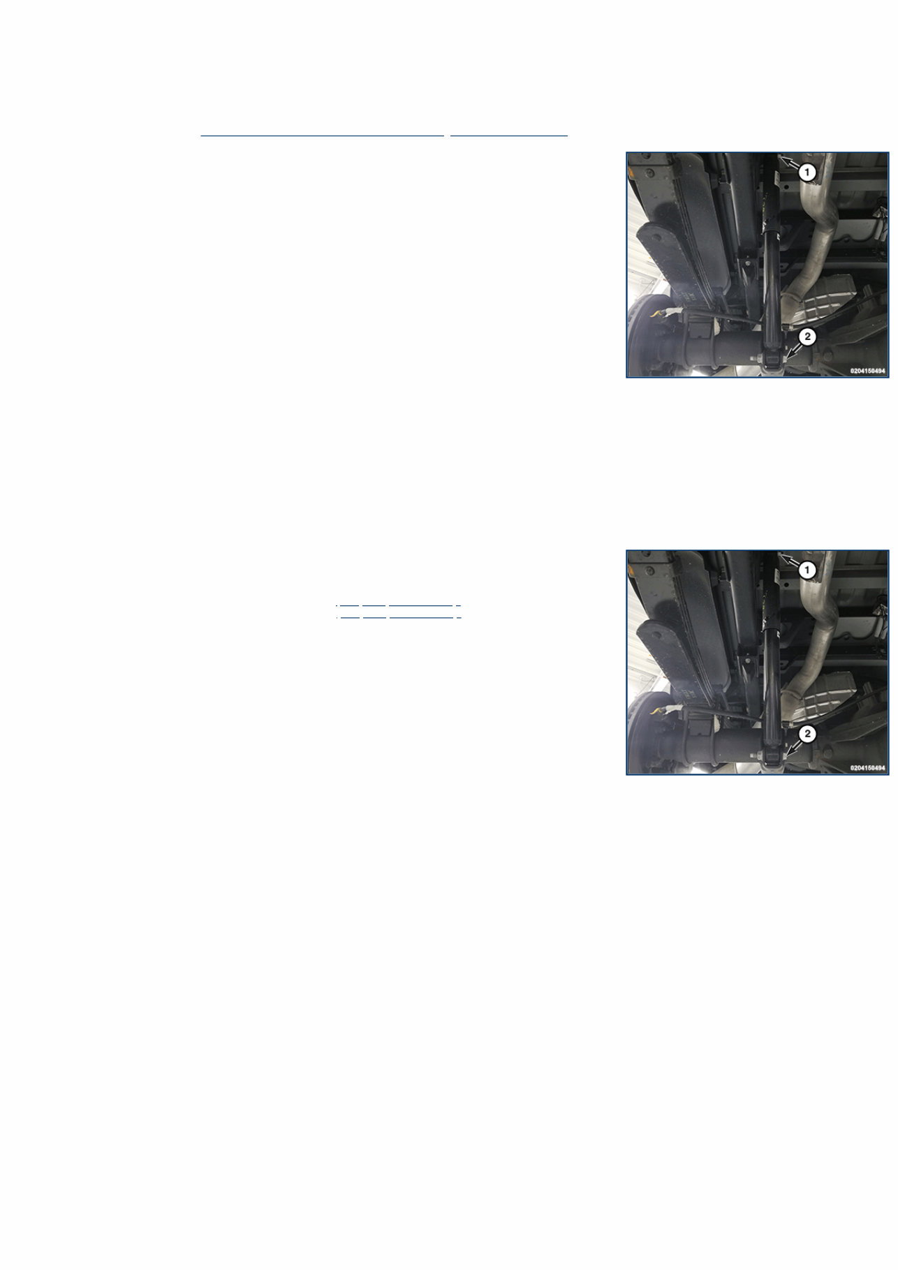
17 - Rear Suspension / SHOCK ABSORBER, Suspension / Removal and Installation REMOVAL AND INSTALLATION REMOVAL 1. Raise and support the vehicle (Refer to 04 - Vehicle Quick Reference/Hoisting/Standard Procedure) . 2. Support the rear axle with a suitable holding fixture. 3. Remove the shock absorber upper nut (1). 4. Remove the shock absorber lower bolt (2) and nut. 5. Remove the shock absorber. INSTALLATION NOTE: In any instance where a bolt is through a rubber bushing, the bolt must be torqued with the vehicle at normal ride height. 1. Position the shock absorber on the upper stud. 2. Position the lower shock absorber in the bracket. 3. Install the shock absorber upper nut (1). Do not tighten. 4. Install the shock absorber lower bolt (2) and nut. Do not tighten. 5. Remove the holding fixture supporting the axle. 6. Remove the support and lower the vehicle. 7. Tighten the shock absorber upper nut (1) to the proper (Torque Specifications) . 8. Tighten the shock absorber lower bolt (2) to the proper (Torque Specifications) .
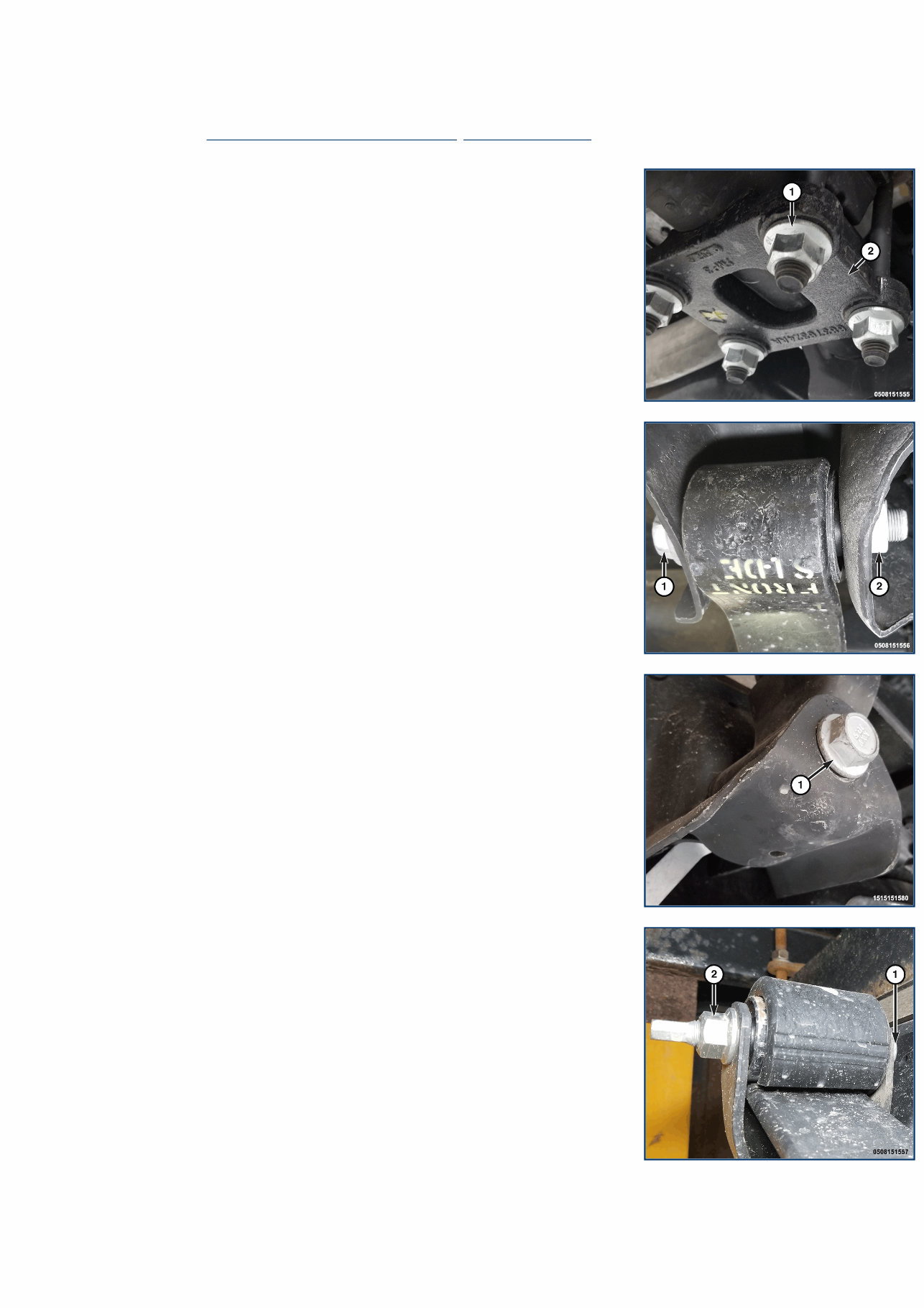
17 - Rear Suspension / SPRING(S) / Removal and Installation REMOVAL AND INSTALLATION REMOVAL 1. Raise and support the vehicle (Refer to 04 - Vehicle Quick Reference/Hoisting - Standard Procedure) . 2. Support the axle with a suitable holding fixture. 3. Remove the four leaf spring axle nuts (1) and remove the plate (2). 4. Remove the leaf spring bolt (1). 5. Remove the shackle bolt (1) and retain the flag nut. 6. Remove the spring from the vehicle. 7. Remove the leaf spring bolt (1) and the spring shackle. INSTALLATION NOTE: In any instance where a bolt is through a rubber bushing, the bolt must be torqued with the vehicle at normal ride height.
NOTE: Springs are marked with “front side”, this end of the spring must mount directly to the frame forward of the axle. 1. Position the spring shackle to the spring then install the leaf spring bolt (1) and tighten to the proper (Torque Specifications) . 2. Position the leaf spring to the axle and to the frame. 3. Place the flag nut in position then install the shackle bolt (1), do not tighten at this time. 4. Align the front spring bushing to the frame then install the leaf spring bolt (1) do not tighten at this time. 5. Position the plate over the u-bolts then install the four leaf spring axle nuts (1) and tighten to the proper (Torque Specifications) . 6. Remove the support and lower the vehicle. 7. Tighten the shackle bolt to the proper (Torque Specifications) . 8. Tighten both leaf spring bolts to the proper (Torque Specifications) .
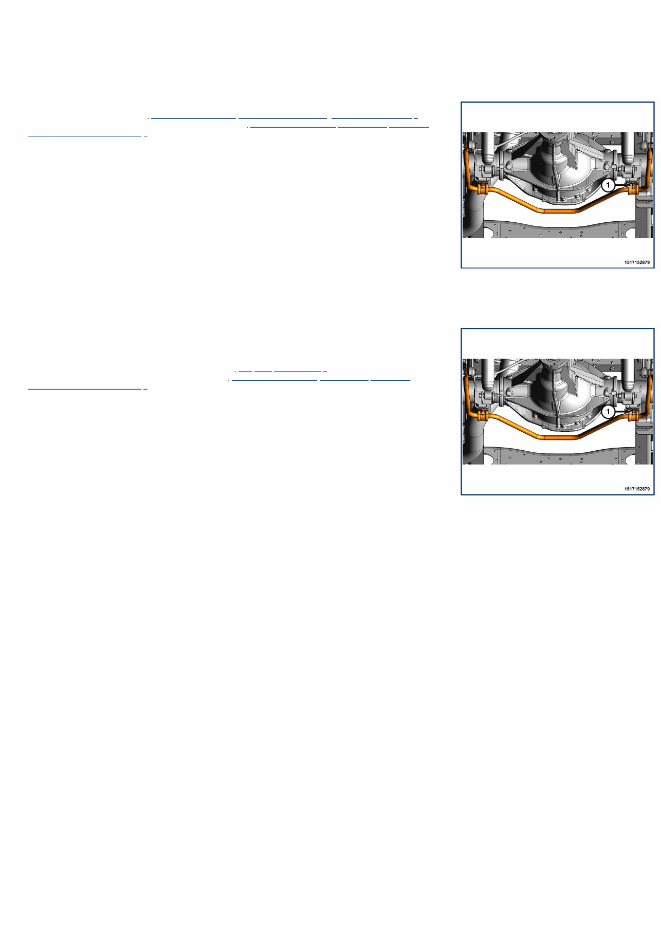
17 - Rear Suspension / STABILIZER BAR, Rear Suspension / Removal and Installation REMOVAL AND INSTALLATION REMOVAL 1. Raise and support the vehicle (Refer to 04 - Vehicle Quick Reference/Hoisting/Standard Procedure) . 2. Remove both stabilizer bar links from the stabilizer bar (Refer to 17 - Rear Suspension/LINK, Stabilizer Bar/Removal and Installation) . 3. Remove the four stabilizer bar nuts (1) and retainers. 4. Remove the stabilizer bar. 5. Remove both stabilizer bar bushings. INSTALLATION 1. Install both stabilizer bar bushings. 2. Install the stabilizer bar and center it with equal spacing on both sides. 3. Install the stabilizer bar retainers and the four stabilizer bar bolts (2). 4. Tighten the four stabilizer bar nuts (2) to the proper (Torque Specifications) . 5. Install both stabilizer bar links to the stabilizer bar (Refer to 17 - Rear Suspension/LINK, Stabilizer Bar/Removal and Installation) . 6. Remove the support and lower the vehicle.
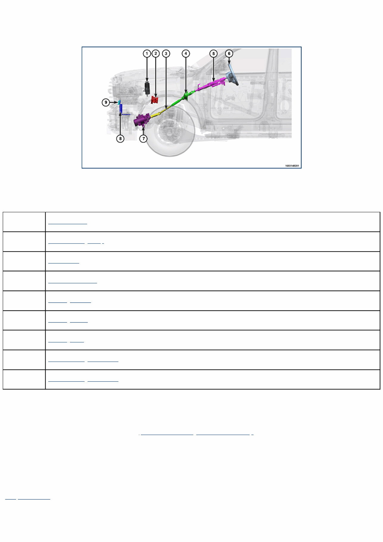
19 - Steering / Description DESCRIPTION AND OPERATION DESCRIPTION The power steering system consists of the following components: Component Index 1. Fluid Reservoir 2. Power Steering Pump 3. Lower Shaft 4. Intermediate Shaft 5. Steering Column 6. Steering Wheel 7. Steering Gear 8. Power Steering Cooler 6.4L 9. Power Steering Cooler 6.7L OPERATION NOTE: On vehicles equipped with Steering Assist Module (SAM) (SJE sales code), relearn the steering angle any time the steering gear input shaft is physically separated from the SCCM (disconnecting intermediate shaft and/or steering column from either end). Refer to the reset Steering Angle Calibration for the SAM (Refer to 19 - Steering/Standard Procedure) . The power steering system utilizes a belt driven hydraulic pump to route fluid through a series of hose to a constant flow rate and displacement, vane-type pump. The power steering gear is a recirculating ball worm (nut) gear type that uses hydraulic pressure to transfer steering torque to the front wheels. The steering system uses an aluminum cross-low cooler mount in front of the radiator to regulate system temperature. This hydraulic power steering system in standard equipment. Fluid Reservoir Component Index The power steering fluid reservoir provides for the expansion and contraction of the fluid due to changed in fluid temperature. Mopar® ATF+4 is to be used in the power steering system. No other power steering or automatic transmission fluid is to be used in the system. Damage may result to the power steering pump and system if any other fluid is used, and do not overfill.
Intermediate Shaft Component Index The intermediate shaft couples the steering column to the lower shaft passing through the vehicle bulkhead. The intermediate shaft transfers the steering wheel torque (side to side movement) to the steering gear using a non-serviceable two piece design joined by a U-joint. Lower Shaft Component Index The lower shaft couples the intermediate shaft to the steering gear. The lower shaft transfers the steering wheel torque (side to side movement) to the steering gear using a non-serviceable two piece design joined by a U-joint. Power Steering Cooler 6.4L Component Index The power steering system cooler is mount in front of the vehicle radiator and uses the engine cooling system to dissipate excess heat to the ambient air. All vehicles are equipped with a power steering fluid cooler. Power Steering Cooler 6.7L Component Index The power steering system cooler is mounted in front of the vehicle radiator and uses the engine cooling system to dissipate excess heat to the ambient air. All vehicles are equipped with a power steering fluid cooler. Power Steering Pump Component Index The pump is connected to the steering gear via the pressure hose and the return hose. The pump shaft has a pressed-on pulley that is belt driven by the crankshaft pulley. Hydraulic pressure is provided for the power steering gear by the belt driven power steering pump. Steering Column Component Index The tilt steering column has been designed to be serviced as an assembly less wiring, switches, shrouds, steering wheel. Most steering column components can be serviced without removing the steering column from the vehicle. There are no serviceable components on the steering column. Steering Gear Component Index Hydraulic pressure is provided for the power steering gear by the belt driven power steering pump. The recirculating ball steering mechanism contains a worm (nut) gear inside a block with a threaded hole in it, this block has gear teeth cut into the outside to engage the sector shaft (also called a sector gear) which moves the pitman arm. Steering Wheel Component Index The steering wheel connects the driver to the front wheels through a series of shafts and steering linkage. The steering wheel also house various vehicle function switches and controls.
19 - Steering / Diagnosis and Testing DIAGNOSIS AND TESTING NOTE: If the vehicle is involved in a collision where the airbag has been deployed or the steering wheel deformed, then steering column replacement is required. STEERING SYSTEM DIAGNOSIS CHARTS NOTE: There are four diagnosis charts following that cover POWER STEERING NOISE, BINDING AND STICKING, INSUFFICIENT ASST. OR POOR RETURN TO CENTER and LOOSE STEERING AND VEHICLE LEAD. NOTE: * There is some noise in all power steering systems. One of the most common is a hissing sound evident when turning the steering wheel when at a standstill or when parking and the steering wheel is at the end of its travel. Hiss is a very high frequency noise similar to that experienced while slowly closing a water tap. The noise is present in every valve and results when high velocity fluid passes valve orifice edges. There is no relationship between this noise and the performance of the steering system. NOTE: ** A light clunk may be felt or heard during steering wheel reversal while vehicle is stationary. This results from internal steering gear rack movement at the bushings and in no way affects the performance of the steering system. This movement may be felt in the steering components during steering wheel reversal. NOTE: *** Power steering pump growl/moan/groan results from the development of high pressure fluid flow. Normally this noise level should not be high enough to be objectionable. POWER STEERING NOISE CONDITION POSSIBLE CAUSES EVALUATION/CORRECTION OBJECTIONABLE HISS OR WHISTLE WHILE TURNING STEERING WHEEL WHEN STATIONARY OR MOVING SLOWLY* 1. Damaged or mispositioned steering column shaft/coupling dash boot seal. 1. Check to ensure boot is properly installed and seals against sheet metal. Reposition or replace steering column shaft/coupling dash boot seal as necessary. 2. Mis-routed power steering hose. 2. Check routing of power steering hoses. Ensure hoses do not come in unwanted contact with other components and objects. 3. Restriction in pressure or return hose. 3. Using an electronic listening tool, determine if noise is coming from either pressure or return hose. Replace hose that noise is present within. 4. Noisy valve in power steering gear. 4. For evaluation and correction, (Refer to 19 - Steering - Diagnosis and Testing) . RATTLE OR EXCESSIVE CLUNK** 1. Power steering gear loose on frame. 1. Check fastener torque and tighten to specifications. Replace as necessary. Check steering wheel center following repair. 2. Loose shock assembly mounting fasteners at tower or knuckle. 2. Check fastener torque and tighten to specifications. 3. Excessive play in outer tie rod. 3. Inspect and replace if necessary. 4. Engine cradle/crossmember mounting fasteners loose at frame or bushings worn. 4. Check fastener torque and tighten to specifications. Inspect bushings and repair as necessary. 5. Wheel mounting (lug) nuts loose. 5. Inspect wheel mounting (lug) nuts and studs and repair as necessary. Tighten nuts to specifications. 6. Power steering hose touching the body or frame of vehicle. 6. For evaluation and correction, (Refer to 19 - Steering/Pump - Diagnosis and Testing) . 7. Stabilizer bar link joints worn (occurs with steering input only when moving, not stationary). 7. At park, jounce only one side of vehicle front to exercise stabilizer bar. Replace stabilizer bar link.
CONDITION POSSIBLE CAUSES EVALUATION/CORRECTION 8. Loose lower control arm mounting bolts at engine cradle, frame or crossmember (occurs with steering input only when moving, not stationary). 8. Check control arm mounting bolts and tighten to specified torque. 9. Loose intermediate shaft or column. 9. Rotate intermediate (steering) shaft in relationship to gear, checking for free- play. Check column fasteners and tighten to specifications as necessary. 10. Lower control arm pivot bushing worn (occurs with steering input only when moving, not stationary). 10. Inspect bushings for wear and replace lower control arm as necessary. 11. Internal power steering gear noise. 11. Drive vehicle on rough road, then steer rapidly back and forth when stopped. Replace power steering gear as necessary. 12. Worn steering tie rods. 12. Inspect and replace if necessary. 13. Damaged engine cradle/crossmember. 13. Inspect the cradle/crossmember for cracks or other damage. Replace as necessary. POPPING NOISE 1. Loose steering gear mounting fasteners. 1. Check fasteners for proper torque and retighten as necessary. 2. Loose outer tie rod mounting nut. 2. Check fastener torque. Replace nuts as necessary and tighten to specifications. 3. Loose intermediate (steering) shaft coupling at gear input shaft. 3. Make sure coupling is fully seated on gear input shaft. Retighten or re-seat as necessary. 4. Worn tie rod (outer or inner). 4. Inspect and replace if necessary. 5. Worn axle half-shaft. 5. Inspect and replace if necessary. CHIRP OR SQUEAL (POWER STEERING PUMP) 1. Loose power steering pump drive belt. 1. Inspect belt. Replace belt if worn or glazed. Tighten/adjust power steering pump drive belt if equipped with a manual tensioner. 2. Pulley alignment incorrect. 2. Realign accessory drives. 4. Power steering pump noisy (worn bearing/bushing noise). 4. Using an electronic listening tool, determine if noise is coming from pump. Replace power steering pump as required. 5. Generator or water pump noisy. 5. Using an electronic listening tool, determine if noise is coming from the generator or water pump. Replace faulty component. WHINE, GROWL, MOAN OR GROAN (POWER STEERING PUMP)*** 1. Low power steering fluid level. 1. Fill power steering fluid reservoir to proper level and check for leaks (make sure all air is bled from the system fluid). 2. Air in power steering fluid. 2. Inspect for excessive air bubbles in fluid (fluid will appear foamy and lighter in color). Inspect hoses for leaks and replace as necessary. Bleed air from fluid (Refer to 19 - Steering/Pump - Standard Procedure) . 3. Power steering hose touching body or frame of vehicle. 3. For evaluation and correction, (Refer to 19 - Steering/Pump - Diagnosis and Testing) . 4. Wear of power steering pump internal components. 4. For evaluation and correction, (Refer to 19 - Steering/Pump - Diagnosis and Testing) . COLD START WHINE OR MOAN (POWER STEERING PUMP)*** 1. Low power steering fluid level. 1. Fill power steering fluid reservoir to proper level and check for leaks (make sure all air is bled from the system fluid). 2. Extremely low ambient temperature (near 0 F° (-18 C°) or below). 2. Some noise is expected as pump attempts to pull cold, thick fluid. Noise should go away as vehicle warms up. Acceptable levels of excessive noise are one second at 0 F° (-18 C°) and 15 seconds at -20 F° (-29 C°). If noise is excessive, look for poor sealing on the return hose or a possible fluid leak.
The 2023 RAM 3500 Cab Chasis Service & Repair Manual Is A Comprehensive Guide For Individuals Looking To Fix Problems On Their Vehicles. It Is A Do-It-Yourself Approach That Includes Every Troubleshooting And Replacement Procedure Provided By The Manufacturer. This Manual Is Equipped With Step-By-Step Instructions, Clear Images, And Exploded-View Illustrations To Assist With Any Repairs That May Be Needed.
While The Durability Of Your Vehicle Is Undeniable, Regular Maintenance Is Still Necessary. Over Time, Certain Parts Will Wear Out And Need To Be Replaced. Fortunately, This Repair Manual Provides Manufacturer-Recommended Troubleshooting Charts And Replacement Procedures, Making It A Valuable Resource For Any Vehicle Owner.
With This Manual, You Can Save On Repair Costs, Increase The Reliability Of Your Vehicle, And Even Avoid Trips To The Repair Shop. It Contains All The Necessary Information To Fix Your Vehicle, Eliminating The Need To Flip Through Hundreds Of Pages Or Deal With Greasy And Torn Pages. You Can Easily Search, Bookmark, And Even Print Specific Information, Making It Much More Convenient Than A Traditional Bound Manual.
This Repair Manual Is Compatible With Various Electronic Devices, Including Pcs, Mac Computers, Android And Apple Smartphones And Tablets. It Only Requires The Free Adobe Reader To Access On Any Device. So Whether You Prefer A Digital Or Physical Copy, The 2023 RAM 3500 Cab Chasis Service & Repair Manual Has You Covered.
Recently Viewed
5,521,897Happy Clients
2,594,462eManuals
1,120,453Trusted Sellers
15Years in Business
Price:
Actual Price:
2023 RAM 3500 Cab Chasis 6.4L V8 Heavy Duty Hemi MDS Service & Repair Manual