CAUTION ALL SERVICE AND REBUILDING INSTRUCTIONS CONTAINED HEREIN ARE APPLICABLE TO, AND FOR THE CONVENIENCE OF, THE AUTOMOTIVE TRADE ONLY. All test and repair procedures on components or assemblies in non-automotive applications should be repaired in accordance with instruc- tions supplied by the manufacturer of the total product. Proper service and repair is important to the safe, reliable, operation of all motor vehicles . The service procedures recommended and described in this publication were developed for pro- fessional service personnel and are effective methods for performing vehicle repair. Following these procedures will help assure efficient economical vehicle performance and service reli- ability. Some of these service procedures require the use of special tools designed for specific procedures . These special tools should be used when recommended throughout this publi- cation . Special attention should be exercised when working with spring or tension loaded fasteners and devices such as E-Clips, Circlips, Snap rings, etc., as careless removal may cause personal injury. Always wear safety goggles whenever work- ing on vehicles or vehicle components. It is important to note that this publication contains various Cautions and Warnings. These should be carefully read in order to minimize the risk of personal injury, or the possibility that improper service methods may damage the vehicle or render it unsafe . It is important to note that these Cautions and Warnings cover only the situations and procedures Chrysler LLC has encountered and recommended. Chrysler LLC could not possibly know, evaluate, ~nd advise the service trade of all conceivable ways that service may be performed, or of the possible hazards of each. Consequently, Chrysler LLC has not undertaken any such broad seNice review. Accordingly, anyone who uses a service procedure, or tool, that is not recom- mended in this publication must assure oneself thoroughly that neither personal safety, nor vehicle safety, be jeopardized by the service methods they select. For other Service and Owner Manuals for Chrysler, Plymouth, Dodge, Dodge Truck, and Jeep® vehicles, Call (800) 890-4038 or FAX (440) 572-0815 to place an order. Or, visit our website at techauthority.com. Tech Authority Online at our website offers you service information on a subscription basis.
FOREWORD The information contained in this service manual has been prepared for the professional automotive tech- nician involved in daily repair operations. Information describing the operation and use of standard and optional equipment is included in the Owner's Manual provided with the vehicle. Information in this manual is divided into groups. These groups contain description, operation, diagnosis, testing, adjustments, removal, installation, disassembly, and assembly procedures for the systems and compo- nents. To assist in locating a group title page, use the Group Tab Locator on the following page. The solid bar after the group title is aligned to a solid tab on the first page of each group. The first page of the group has a contents sect jon that lists major topics within the group. If you are not sure which Group contains the infor- mation you n~d, look up the Component/System in the alphabetical index located in the rear of this manual. A Service Manual Comment form is included at the rear of this manual. Use the form to provide Chrysler LLC with your comments and suggestions. ~, Tighten~*g- torques are provided as a specific value throughout this manual. This value represents the mid- point of ~,_aeceptable engineering torque range for a given fastener application. These torqti~ values are intended for use in service assembly and installation procedures using the correct OEM -fa~~-eners. When replacing fasteners, always use the same type (part number) fastener as removed. '~'~ .~ :, Chrysler LLC reserves the right to change testing procedures, specifications, diagnosis, repair':'methods, or vehicle 'Yiring at any time without prior notice or incurring obligation. .. .:.- ~
2008 RAM TRUCK INCLUDES SRT-10 AND DIESEL SERVICE MANUAL GROUP TAB LOCATOR Introduction 0 Lubrication & Maintenance 2 Suspension 3 Differential & Drlvellne 4 Vehicle Quick Reference 5 Brakes 6 Clutch 7 Cooling 8A AudiolVideo 8B Chime/Buzzer 8E Electronic Control Modules 8F Engine Systems 8G Heated Systems 8H Horn 8. Ignition Control 8J Instrument Cluster 8L Lamps 8M Message Systems 8N Power Systems 80 Restraints 8P Speed Control 8Q Vehicle Theft Security 8R WiperslWashers 8T NavigationfTelecommunication 8W Wiring 9 Engine 11 Exhsust System 13 Frame & Bumpers 14 Fuel System 19 Steering 21 Transmission and Transfer Case 22 TireslWheels 23 Body 24 Heating 8. Air Conditioning 25 Emissions Control Component and System Index DTClndex Service Manual Comment Forms (Rear of Manual)
DR ---------------------INTRODUCTION 1 INTRODUCTION TABLE OF CON-rENTS page VEHICLE IDENTIFICATION NUMBER DESCRIPTION - VIN CODING/LOCATIONS ...... 2 VEHICLE EMISSION CONTROL INFORMATION (VECI) DESCRIPTION ................................. 4 BODY CODE PLATE DESCRIPTION ................................. 5 INTERNATIONAL VEHICLE CONTROL & DISPLAY SYMBOLS DESCRIPTION - INTERNATIONAL SYMBOLS ..... 9 FASTENER IDENTIFICATION DESCRIPTION ................................ 10 FASTENER USAGE DESCRIPTION page FASTENER USAGE ......................... 12 THREADED HOLE REPAIR DESCRIPTION THREADED HOLE REPAIR .................. 13 METRIC SYSTEM DESCRIPTION ................................ 14 TORQUE REFERENCES DESCRIPTION ................................ 16 VEHICLE CERTIFICATION LABEL DESCRIPTION ................................ 17 -
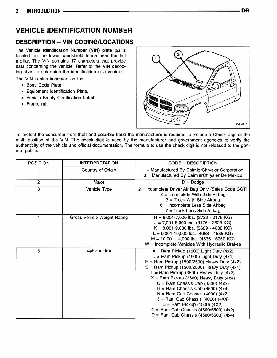
2 INTRODUCTION --------------------- DR VEHICLE IDENTIFICATION NliMBER DESCRIPTION - VIN CODING/LOCATIONS The Vehicle Identification Number (VIN) plate (2) is located on the lower windshield fence near the left a-pillar. The VIN contains 17 characters that provide data concerning the vehicle. Refer to the VIN decod- ing chart to determine the identification of a vehicle. The VIN is also imprinted on the: • Body Code Plate. • Equipment Identification Plate. • Vehicle Safety Certification Label. • Frame rail. To protect the consumer from theft and possible fraud the manufacturer is required to include a Check Digit at the ninth position of the VIN. The check digit is used by the manufacturer and government agencies to verify the authenticity of the vehicle and official documentation. The formula to use the check digit is not released to the gen- eral public. POSITION INTERPRETATION CODE;;;; DESCRIPTION 1 Country of Origin 1 Manufactured By DaimlerChrysler Corporation 3 Manufactured By DaimlerChrysler De Mexico 2 Make D = Dodge 3 Vehicle Type 2 ;;;; Incomplete Driver Air Bag Only (Sales Code CGT) 2 ;;;; Incomplete With Side Airbag 3 = Truck With Side Airbag 6 = Incomplete Less Side Airbag 7 = Truck Less Side Airbag 4 Gross Vehicle Weight Rating H = 6,001-7,000 Ibs. (2722 - 3175 KG) J = 7,001-8,000 Ibs. (3176 - 3628 KG) K = 8,001-9,000 Ibs. (3629 - 4082 KG) L;;;; 9,001-10,000 Ibs. (4083 - 4535 KG) M = 10,001-14.000 Ibs. (4536 6350 KG) W;;;; Incomplete Vehicles With Hydraulic Brakes 5 Vehicle Line A;;;; Ram Pickup (1500) Light Duty (4x2) U = Ram Pickup (1500) Light Duty (4x4) R = Ram Pickup (1500/2500) Heavy Duty (4x2) S ;;;; Ram Pickup (1500/2500) Heavy Duty (4x4) L ;;;; Ram Pickup (3500) Heavy Duty (4x2) X;;;; Ram Pickup (3500) Heavy Duty (4x4) G = Ram Chassis Cab (3500) (4x2) H = Ram Chassis Cab (3500) (4x4) N = Ram Cab Chassis (4000) (4x2) 3 = Ram Cab Chassis (4000) (4X4) 5 = Ram Pickup (1500) (4X2) C = Ram Cab Chassis (4500/5500) (4x2) D = Ram Cab Chassis (4500/5500) (4x4)
DR ----------------------INTRODUCTION 3 POSITION INTERPRETATION CODE = DESCRIPTION a Series 1 = 1500 2 = 2500 3 = 3500 Less Dual Re,ar Wheels 4 = 3500 With Dual Rear Wheels 5 = 4000 OX Family a = 4500 With Dual Rear Wheels 7 = 5500 With Dual Rear Wheels 7 Body Style 6 = Conventional Cab/Cab Chassis 8 = Quad Cab Full Rear Doors 9 = Mega Cab Ram Pickup a Engine K = 3.7L va CYL Magnum Gasoline N == 4.7L va CYL Gasoline D::: 5.7L va CYL Magnum Gasoline SMPI 2 = 5.7L va CYL HEMI Multiple Displacement Gasoline C = 5.9L 16 CYL Turbo Diesel High Output A = 6.7L 16 CYL Cummins Turbo Diesel 9 Check Digit o through 9 or X 10 Model Year 8 = 200a 11 Plant Location S = Warren Truck Assembly G = Saltillo J = St. Louis (North) 12 -17 Vehicle Build Sequence
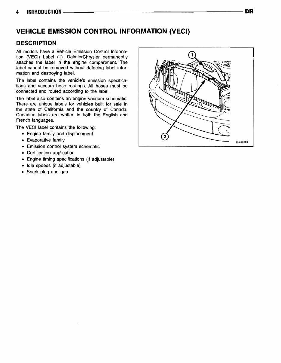
4 INTRODUCTION ---------------------- DR VEHICLE EMISSION CONTROL INFORMATION (VECI) DESCRIPTION All models have a Vehicle Emission Control Informa- tion (VECI) Label (1). DaimlerChrysler permanently attaches the label in the engine compartment. The label cannot be removed without defacing label infor- mation and destroying label. The label contains the vehicle's emission specifica- tions and vacuum hose routings. All hoses must be connected and routed according to the label. The label also contains an engine vacuum schematic. There are unique labels for vehicles built for sale in the state of California and the country of Canada. Canadian labels are written in both the English and French languages. The VEel label contains the following: • Engine family and displacement • Evaporative family • Emission control system schematic • Certification application • Engine timing specifications (if adjustable) • Idle speeds (if adjustable) • Spark plug and gap 80cd9d69
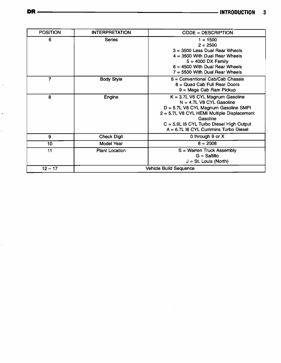
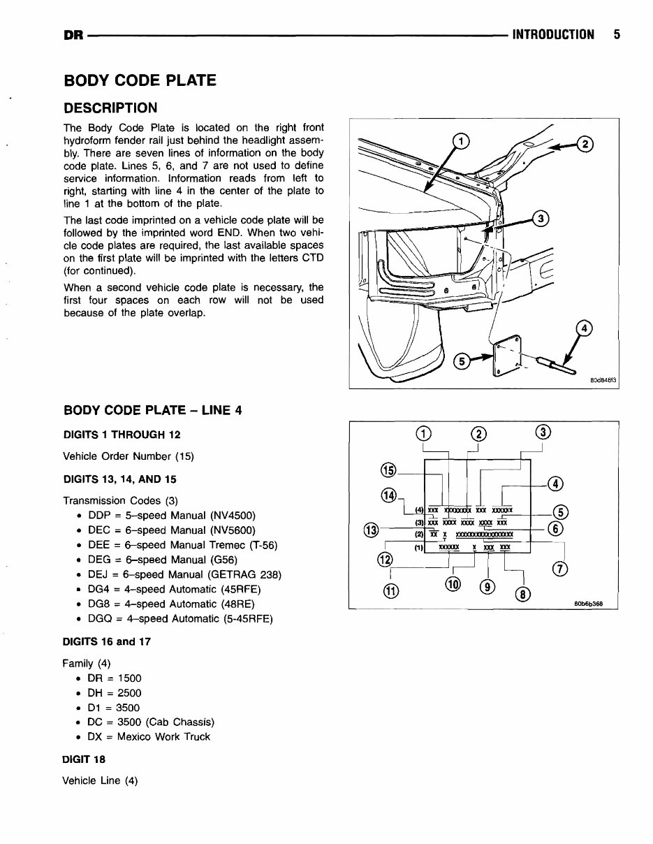
DR ---------------------- INTRODUCTION 5 BODY CODE PLATE DESCRIPTION The Body Code Plate is located on the right front hydroform fender rail just behind the headlight assem- bly. There are seven lines of information on the body code plate. Lines S. 6. and 7 are not used to define service information. Information reads from left to right. starting with line 4 in the center of the plate to line 1 at the bottom of the plate. The last code imprinted on a vehicle code plate will be followed by the imprinted word END. When two vehi- cle code plates are required, the last available spaces on the first plate will be imprinted with the letters CTD (for continued). When a second vehicle code plate is necessary. the first four spaces on each row will not be used because of the plate overlap. BODY CODE PLATE - LINE 4 DIGITS 1 THROUGH 12 Vehicle Order Number (15) DIGITS 13, 14, AND 15 Transmission Codes (3) • DDP = 5-speed Manual (NV4S00) • DEC ;;;;; 6-speed Manual (NV5600) • DEE = 6-speed Manual Tremec (T-56) • DEG = 6-speed Manual (G56) • DEJ 6-speed Manual (GETRAG 238) • DG4 = 4-speed Automatic (45RFE) • DG8;;;;; 4-speed Automatic (48RE) • DGQ = 4-speed Automatic (5-4SRFE) DIGITS 16 and 17 Family (4) • DR = 1500 • DH ;;;;; 2500 • 01 ;;;;; 3500 • DC 3500 (Cab Chassis) • DX Mexico Work Truck DIGIT 18 Vehicle Line (4) CD , ...... ----t.-w r-------I--® t.f3\-----(3-+' --.xxx xxxx XXX)( xxxx xxx ® ~ (2) xx x lOOXXX.XlOOCXXXXXXX ...-------f----' (1) xx:xxxx x xxx xxx @ .---------' (j) ® ® BOb6b368
This truck repair manual is essential for both professional mechanics and DIY enthusiasts. It contains troubleshooting and replacement procedures provided by the manufacturer, including step-by-step instructions, clear images, and exploded-view illustrations.
Regular maintenance is crucial for the durability of your truck. Over time, some parts will wear out and need replacement. This manual provides the manufacturer's recommended troubleshooting charts and replacement procedures, helping you save on repairs and increase your vehicle’s reliability.
No need to flip through hundreds of pages to find specific information. This .pdf format manual is easily accessible and printable, compatible with various electronic devices, and requires Adobe Reader (free) for viewing.