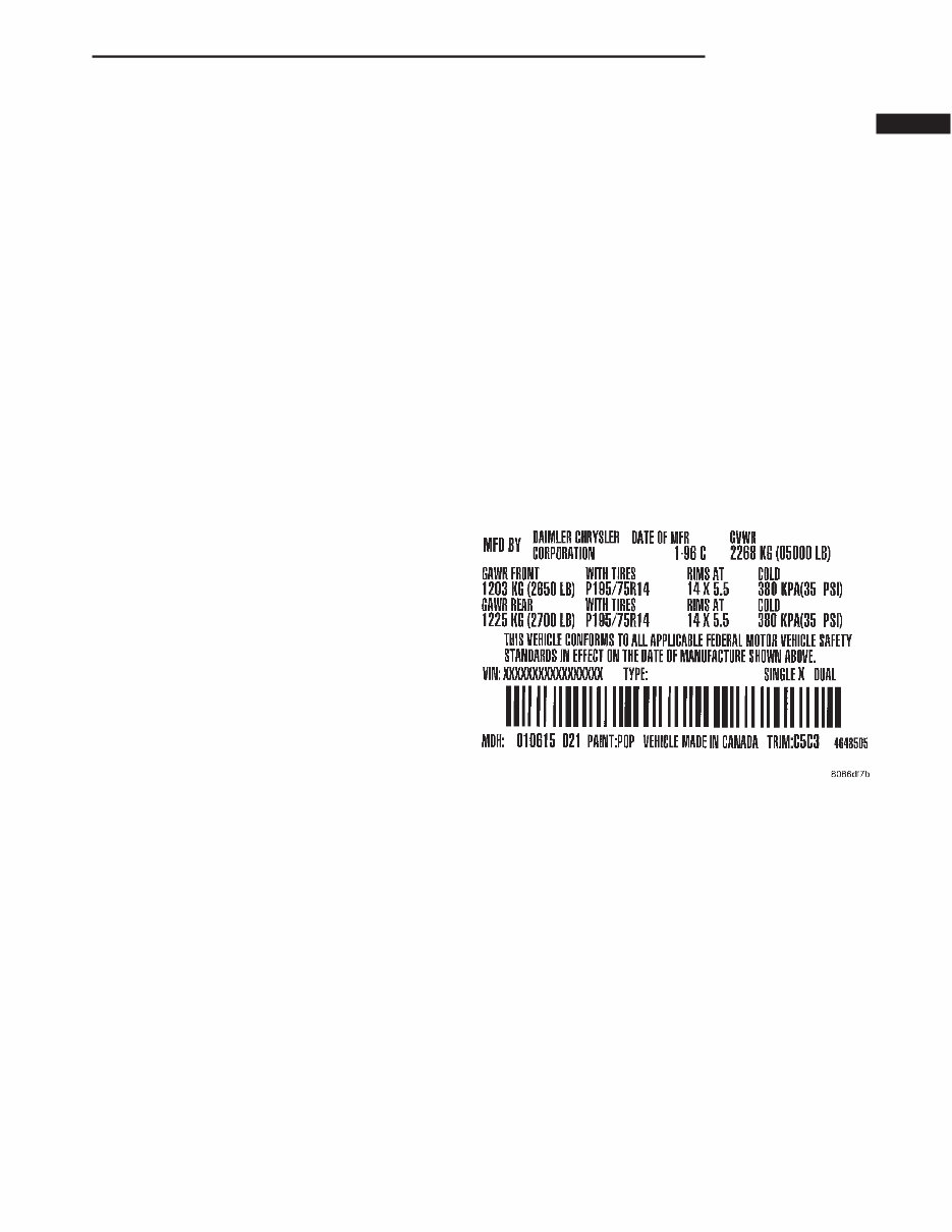
INTRODUCTION TABLE OF CONTENTS page page VEHICLE SAFETY CERTIFICATION LABEL DESCRIPTION .......................... 1 VEHICLE IDENTIFICATION NUMBER DESCRIPTION .......................... 2 VEHICLE EMISSION CONTROL INFORMATION (VECI) DESCRIPTION .......................... 3 BODY CODE PLATE DESCRIPTION .......................... 3 INTERNATIONAL VEHICLE CONTROL & DISPLAY SYMBOLS DESCRIPTION - INTERNATIONAL SYMBOLS ...5 FASTENER IDENTIFICATION DESCRIPTION .......................... 5 FASTENER USAGE DESCRIPTION - FASTENER USAGE ......... 8 THREADED HOLE REPAIR DESCRIPTION - THREADED HOLE REPAIR .... 8 METRIC SYSTEM DESCRIPTION .......................... 8 TORQUE REFERENCES DESCRIPTION ......................... 10 VEHICLE SAFETY CERTIFICATION LABEL DESCRIPTION A vehicle safety certification label (Fig. 1) is attached to every DaimlerChrysler Corporation vehi- cle. The label certifies that the vehicle conforms to all applicable Federal Motor Vehicle Safety Standards. The label also lists: • Month and year of vehicle manufacture. • Gross Vehicle Weight Rating (GVWR). The gross front and rear axle weight ratings (GAWR’s) are based on a minimum rim size and maximum cold tire inflation pressure. • Vehicle Identification Number (VIN). • Type of vehicle. • Type of rear wheels. • Bar code. • Month, Day and Hour (MDH) of final assembly. • Paint and Trim codes. • Country of origin. The label is located on the driver-side door shut- face. Fig. 1 VEHICLE SAFETY CERTIFICATION LABEL - TYPICAL DR INTRODUCTION 1
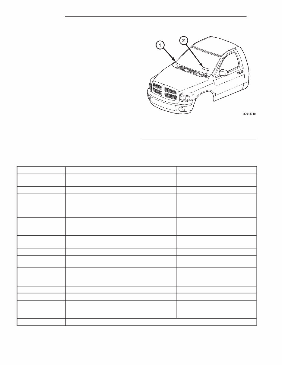
VEHICLE IDENTIFICATION NUMBER DESCRIPTION VIN CODING/LOCATIONS The Vehicle Identification Number (VIN) plate is located on the lower windshield fence near the left a-pillar (Fig. 2). The VIN contains 17 characters that provide data concerning the vehicle. Refer to the VIN decoding chart to determine the identification of a vehicle. The VIN is also imprinted on the: • Body Code Plate. • Equipment Identification Plate. • Vehicle Safety Certification Label. • Frame rail. To protect the consumer from theft and possible fraud the manufacturer is required to include a Check Digit at the ninth position of the VIN. The check digit is used by the manufacturer and govern- ment agencies to verify the authenticity of the vehi- cle and official documentation. The formula to use the check digit is not released to the general public. POSITION INTERPRETATION CODE = DESCRIPTION 1 Country of Origin 1 = United States 3 = Mexico 2 Make B = Dodge 3 Vehicle Type 2 = Incomplete with Side Airbag 3 = Truck with Side Airbag 6 = Incomplete Less Side Airbag 7 = Truck Less Side Airbag 4 Gross Vehicle Weight Rating H = 6,001-7,000 lbs. W = Buses/Incomplete Vehicles with Hydraulic Brakes 5 Vehicle Line A = Ram Pickup 4X2 U = Ram Pickup 4X4 6 Series Ram Pickup 1 = 1500 7 Body Style 6 = Conventional Cab 8 = Quad Cab Full Rear Doors 8 Engine K = 3.7L 6 cyl. MPI N = 4.7L 8 cyl. MPI Z = 5.9L 8 cyl. MPI-LDC 9 Check Digit 0 through 9 or X 10 Model Year 2=2002 11 Plant Location S = Dodge City G = Saltillo J = St. Louis (North) 12 thru 17 Vehicle Build Sequence Fig. 2 VIN LOCATION 1 - DASH PANEL 2 - VIN CODE PLATE 2 INTRODUCTION DR
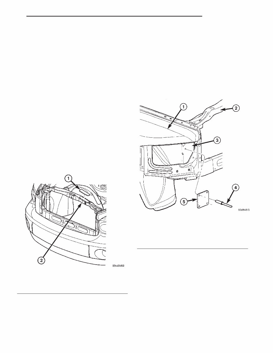
VEHICLE EMISSION CONTROL INFORMATION (VECI) DESCRIPTION All models have a Vehicle Emission Control Infor- mation (VECI) Label. DaimlerChrysler permanently attaches the label in the engine compartment (Fig. 3). The label cannot be removed without defacing label information and destroying label. The label contains the vehicle’s emission specifica- tions and vacuum hose routings. All hoses must be connected and routed according to the label. The label also contains an engine vacuum sche- matic. There are unique labels for vehicles built for sale in the state of California and the country of Canada. Canadian labels are written in both the English and French languages. The VECI label contains the following: • Engine family and displacement • Evaporative family • Emission control system schematic • Certification application • Engine timing specifications (if adjustable) • Idle speeds (if adjustable) • Spark plug and gap BODY CODE PLATE DESCRIPTION The Body Code Plate (Fig. 5) is located on the right front hydroform fender rail just behind the headlight assembly (Fig. 4). There are seven lines of informa- tion on the body code plate. Lines 5, 6, and 7 are not used to define service information. Information reads from left to right, starting with line 4 in the center of the plate to line 1 at the bottom of the plate. The last code imprinted on a vehicle code plate will be followed by the imprinted word END. When two vehicle code plates are required, the last available spaces on the first plate will be imprinted with the letters CTD (for continued). When a second vehicle code plate is necessary, the first four spaces on each row will not be used because of the plate overlap. BODY CODE PLATE—LINE 4 DIGITS 1 THROUGH 12 Vehicle Order Number DIGITS 13, 14, AND 15 Transmission Codes • DGT = 4–speed Automatic (46RE) • DG4 = 4–speed Automatic (45RFE) • DDC = 5–speed Manual (NVG-3500) DIGITS 16, 17, AND 18 Car Line Shell • DR1 = 1500 4 X 2 • DR6 = 1500 4 X 4 Fig. 3 VEHICLE EMISSIONS CERTIFICATION INFORMATION LABEL 1 - VECI LABEL LOCATION 2 - RADIATOR SUPPORT Fig. 4 BODY CODE PLATE LOCATION 1 - FENDER 2 - RADIATOR CROSSMEMBER 3 - HYDROFORM FENDER RAIL 4 - RIVOT (2) 5 - BODY CODE PLATE DR INTRODUCTION 3
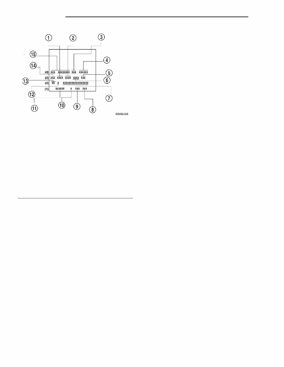
DIGIT 19 Price Class • L = Ram Truck (All) DIGITS 20 AND 21 Body Type • 41 = Ram Truck Quad Cab, Short Box • 42 = Ram Truck Quad Cab, Long Box • 61 = Ram Truck Standard Cab, Short Box • 62 = Ram Truck Standard Cab, Long Box BODY CODE PLATE—LINE 3 DIGITS 1,2, AND 3 Paint Procedure • APA = Monotone • AP9 = Special • APD = Two-tone (Lower break) DIGIT 4 Open Space DIGITS 5 THROUGH 8 Primary Paint (Refer to 23 - BODY/PAINT - SPECIFICATIONS) for color codes. DIGIT 9 Open Space DIGITS 10 THROUGH 13 Secondary Paint DIGIT 14 Open Space DIGITS 15 THROUGH 18 Interior Trim Code DIGIT 19 Open Space DIGITS 20, 21, AND 22 Engine Code • EKG = 3.7 L 6 cyl. MPI Gasoline • EVA = 4.7 L 8 cyl. MPI Gasoline • EML = 5.9 L 6 cyl. MPI Gasoline BODY CODE PLATE—LINE 2 DIGIT 1 Open Space DIGITS 2 AND 3 Species Code. (Used for Manufacturing) DIGIT 4 Open Space DIGIT 5 Market Code • B = International • C = Canada • M = Mexico • U = United States DIGIT 6 Open Space DIGITS 7 THROUGH 23 Vehicle Identification Number (VIN) (Refer to INTRODUCTION/VEHICLE INFORMA- TION/VEHICLE IDENTIFICATION NUMBER - DESCRIPTION) for proper breakdown of VIN code. BODY CODE PLATE—LINE 1 DIGITS 1 THROUGH 6 Body-in-white assembly sequence. DIGIT 7 Open Space DIGIT 8 Tailgate trim code. DIGIT 9 Open Space Fig. 5 BODY CODE PLATE 1 - PRIMARY PAINT 2 - SECONDARY PAINT 3 - TRANSMISSION CODE 4 - VEHICLE MODEL NUMBER 5 - ENGINE CODE 6 - INTERIOR TRIM CODE 7 - VEHICLE IDENTIFICATION NUMBER 8 - TAILGATE CODE 9 - CARGO BOX CODE 10 - TAILGATE TRIM CODE 11 - BODY-IN-WHITE SEQUENCE 12 - MARKET CODE 13 - SPECIES CODE 14 - PAINT PROCEDURE 15 - VEHICLE ORDER NUMBER 4 INTRODUCTION DR BODY CODE PLATE (Continued)
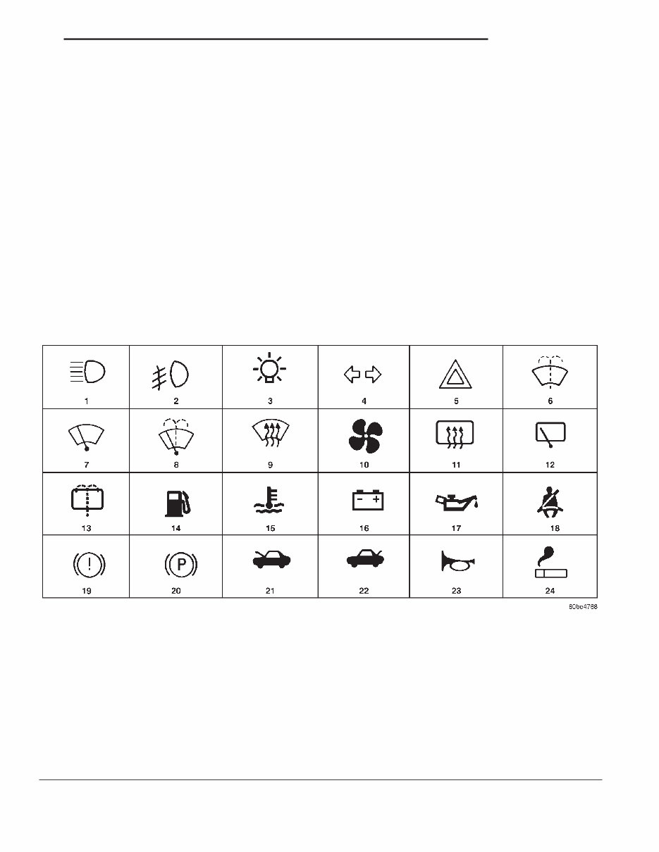
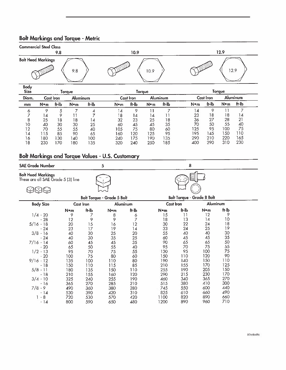
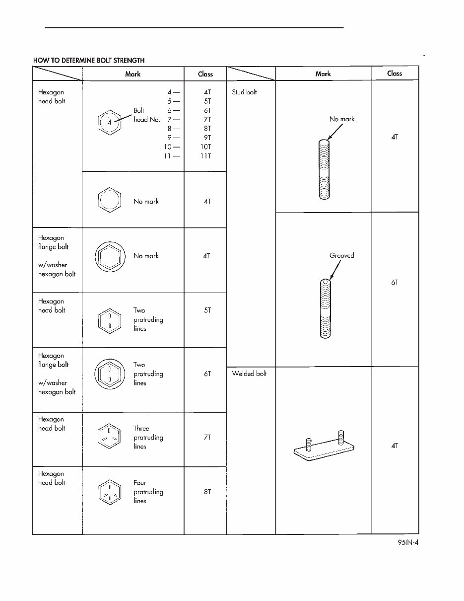
DIGITS 10 THROUGH 12 Cargo box code DIGIT 13 Open Space DIGITS 14 THROUGH 16 Tailgate code INTERNATIONAL VEHICLE CONTROL & DISPLAY SYMBOLS DESCRIPTION - INTERNATIONAL SYMBOLS The graphic symbols illustrated in the following International Control and Display Symbols Chart are used to identify various instrument controls. The symbols correspond to the controls and displays that are located on the instrument panel. FASTENER IDENTIFICATION DESCRIPTION The SAE bolt strength grades range from grade 2 to grade 8. The higher the grade number, the greater the bolt strength. Identification is determined by the line marks on the top of each bolt head. The actual bolt strength grade corresponds to the number of line marks plus 2. The most commonly used metric bolt strength classes are 9.8 and 10.9. The metric strength class identification number is imprinted on the head of the bolt. The higher the class number, the greater the bolt strength. Some metric nuts are imprinted with a single-digit strength class on the nut face. Refer to the Fastener Identification and Fastener Strength Charts (Fig. 6) and (Fig. 7). INTERNATIONAL SYMBOLS 1 High Beam 13 Rear Window Washer 2 Fog Lamps 14 Fuel 3 Headlamp, Parking Lamps, Panel Lamps 15 Engine Coolant Temperature 4 Turn Warning 16 Battery Charging Condition 5 Hazard Warning 17 Engine Oil 6 Windshield Washer 18 Seat Belt 7 Windshield Wiper 19 Brake Failure 8 Windshield Wiper and Washer 20 Parking Brake 9 Windscreen Demisting and Defrosting 21 Front Hood 10 Ventilating Fan 22 Rear hood (Decklid) 11 Rear Window Defogger 23 Horn 12 Rear Window Wiper 24 Lighter DR INTRODUCTION 5 BODY CODE PLATE (Continued)
Fig. 6 FASTENER IDENTIFICATION 6 INTRODUCTION DR FASTENER IDENTIFICATION (Continued)
Fig. 7 FASTENER STRENGTH DR INTRODUCTION 7 FASTENER IDENTIFICATION (Continued)
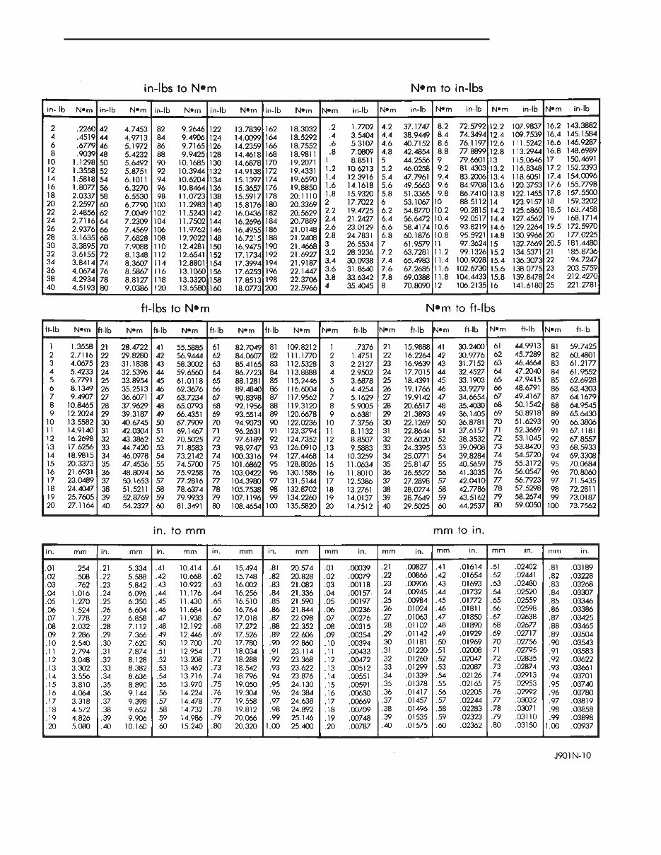
FASTENER USAGE DESCRIPTION - FASTENER USAGE WARNING: USE OF AN INCORRECT FASTENER MAY RESULT IN COMPONENT DAMAGE OR PER- SONAL INJURY. Fasteners and torque specifications references in this Service Manual are identified in metric and SAE format. During any maintenance or repair procedures, it is important to salvage all fasteners (nuts, bolts, etc.) for reassembly. If the fastener is not salvageable, a fastener of equivalent specification must be used. THREADED HOLE REPAIR DESCRIPTION - THREADED HOLE REPAIR Most stripped threaded holes can be repaired using a Helicoilt. Follow the vehicle or Helicoilt recommen- dations for application and repair procedures. METRIC SYSTEM DESCRIPTION The metric system is based on quantities of one, ten, one hundred, one thousand and one million. The following chart will assist in converting metric units to equivalent English and SAE units, or vise versa. CONVERSION FORMULAS AND EQUIVALENT VALUES MULTIPLY BY TO GET MULTIPLY BY TO GET in-lbs x 0.11298 = Newton Meters (N·m) N·m x 8.851 = in-lbs ft-lbs x 1.3558 = Newton Meters (N·m) N·m x 0.7376 = ft-lbs Inches Hg (60° F) x 3.377 = Kilopascals (kPa) kPa x 0.2961 = Inches Hg psi x 6.895 = Kilopascals (kPa) kPa x 0.145 = psi Inches x 25.4 = Millimeters (mm) mm x 0.03937 = Inches Feet x 0.3048 = Meters (M) M x 3.281 = Feet Yards x 0.9144 = Meters M x 1.0936 = Yards mph x 1.6093 = Kilometers/Hr. (Km/h) Km/h x 0.6214 = mph Feet/Sec x 0.3048 = Meters/Sec (M/S) M/S x 3.281 = Feet/Sec mph x 0.4470 = Meters/Sec (M/S) M/S x 2.237 = mph Kilometers/Hr. (Km/h) x 0.27778 = Meters/Sec (M/S) M/S x 3.600 Kilometers/Hr. (Km/h) COMMON METRIC EQUIVALENTS 1 inch = 25 Millimeters 1 Cubic Inch = 16 Cubic Centimeters 1 Foot = 0.3 Meter 1 Cubic Foot = 0.03 Cubic Meter 1 Yard = 0.9 Meter 1 Cubic Yard = 0.8 Cubic Meter 1 Mile = 1.6 Kilometers Refer to the Metric Conversion Chart to convert torque values listed in metric Newton- meters (N·m). Also, use the chart to convert between millimeters (mm) and inches (in.) (Fig. 8). 8 INTRODUCTION DR
Fig. 8 METRIC CONVERSION CHART DR INTRODUCTION 9 METRIC SYSTEM (Continued)
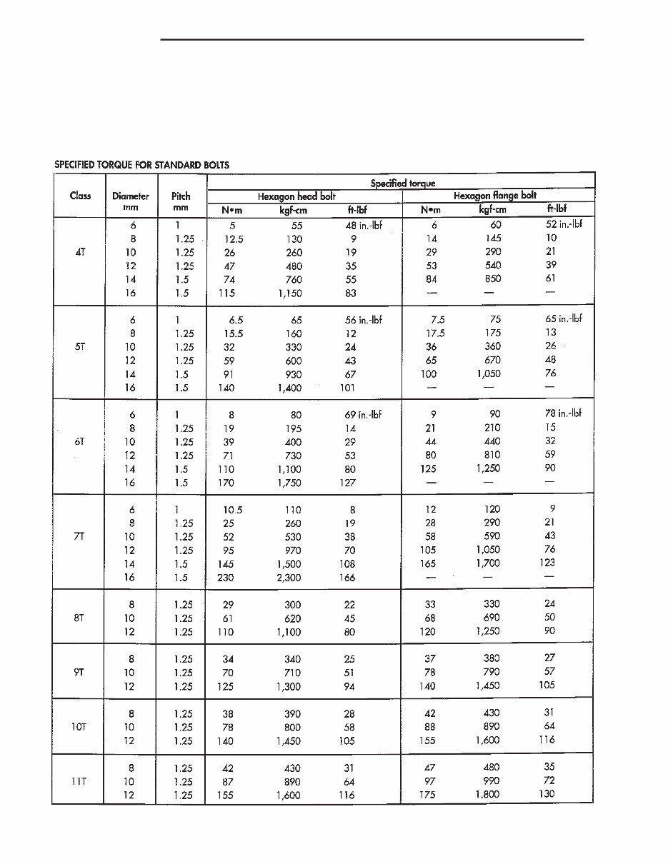
TORQUE REFERENCES DESCRIPTION Individual Torque Charts appear within many or the Groups. Refer to the Standard Torque Specifica- tions Chart for torque references not listed in the individual torque charts (Fig. 9). Fig. 9 TORQUE SPECIFICATIONS 10 INTRODUCTION DR
The 2003 Dodge Ram 3500 OEM Service & Repair Manual is the factory reference designed for maintaining and repairing Ram 3500 models equipped with the 5.9L Magnum V8, 8.0L Magnum V10, and 5.9L Cummins ISB turbo diesel. Transmission coverage includes both automatic (42RE, 46RE, 47RE) and manual (NVG-3500, NVG-4500, NVG-5600) gearboxes.
This manual provides clear step-by-step service instructions for engine diagnostics, lubrication, clutch systems, cooling, driveline, and suspension. It also details brake system procedures, including ABS components, plus steering column and gear service. Electrical and electronic sections cover everything from control module testing to power system checks, with additional guidance on instruments, lamps, speed control, airbags, and theft prevention systems.
Content overview:
Complete lubrication and maintenance procedures
Front and rear suspension service information
Driveline and differential diagnostics and repairs
Brake system service including hydraulics and ABS
Clutch system removal, inspection, and adjustment
Cooling system diagnostics and repair procedures
Audio system and chime/buzzer troubleshooting
Electronic control module locations and testing
Engine systems diagnostics and mechanical service
Heated components and system repair
Horn system and circuit troubleshooting
Ignition system diagnostics and component testing
Instrument cluster removal and fault isolation
Lamp and lighting circuit service procedures
Message systems and dashboard communications
Power system wiring and operation checks
Airbag and restraint system diagnostics
Speed control and cruise system servicing
Vehicle theft security system diagnostics
Wiper and washer motor and switch repairs
Complete wiring diagrams and harness routing
Engine mechanical service and overhaul
Exhaust system inspection and replacement
Frame, bumper, and structural body service
Fuel system pressure, flow, and injection details
Steering column, gear, and pump service
Transmission and transfer case diagnostics
Tires and wheels, balancing, and torque specs
Body panels, trim, and repair procedures
Heating and air conditioning troubleshooting
Emissions control system testing and compliance
Practical for both DIY owners and professional technicians, the manual includes maintenance schedules, torque specifications, and overhaul procedures for all major systems. From body panel repair to HVAC and emissions servicing, it’s a complete guide to keeping a Ram 3500 running at factory standards.
Printable: Yes Language: English Compatibility: Pretty much any electronic device, incl. PC & Mac computers, Android and Apple smartphones & tablet, etc. Requirements: Adobe Reader (free)