1996-1997 Dodge Ram 1500 Series Service & Repair Manual
What's Included?
Lifetime Access
Fast Download Speeds
Online & Offline Access
Access PDF Contents & Bookmarks
Full Search Facility
Print one or all pages of your manual
FOREWORD The information contained in this service manual has been prepared for the professional automotive tech- nician involved in daily repair operations. This manual does not cover theory of operation, which is addressed in service training material. Information describing the operation and use of standard and optional equipment is included in the Owner's Manual provided with the vehicle. Information in this manual is divided into groups. These groups contain general information, diagnosis, testing, adjustments, removal, installation, disassembly, and assembly procedures for the systems and compo- nents. To assist in locating a group title page, use the Group Tab Locator on the following page. The solid bar after the group title is aligned to a solid tab on the first page of each group. The first page of the group has a contents section that lists major topics within the group. I f you are not sure which Group contains the infor- mation you need, look up the Component/System in the alphabetical index located in the rear of this manual. A Service Manual Comment form is included at the rear of this manual. Use the form to provide Chrysler Corporation with your comments and suggestions. Tightening torques are provided as a specific value throughout this manual. This value represents the midpoint of the acceptable engineering torque range for a given fastener application. These torque values are intended for use in service assembly and installation procedures using the correct OEM fasteners. When replacing fasteners, always use the same type (part number) fastener as removed. Chrysler Corporation reserves the right to change testing procedures, specifications, diagnosis, repair methods, or vehicle wiring at any time without prior notice or incurring obligation.
GROUP TAB LOCATOR Introduction life! Lubrication and Maintenance 2 Suspension Differential and Driveline Brakes Clutch 7 Cooling System 8A Battery 8B Starting Systems 8C Charging System 8D Ignition System 8E Instrument Panel Systems 8F Audio Systems 8G Horn Systems 8H Vehicle Speed Control System 8 J Turn Signal and Hazard Warning Systems 8P 8K Wiper and Washer Systems 8L Lamps 8M Passive Restraint Systems Power Door Locks 8R Power Seat Systems 8S Power Window Systems 8T Power Mirror Systems 8U Chime/Buzzer Warning Systems 8V Overhead Console Systems 8W Wiring Diagrams Q Engine j 1 Exhaust System and Intake Manifold j 3 Frame and Bumpers 14 Fuel System j 9 Steering 21 Transmission and Transfer Case 22 Tires and Wheels Hi 23 Body 24 Heating and Air Conditioning 25 Emission Control Systems Component and System Index Service Manual Comment Forms (Rear of Manual)
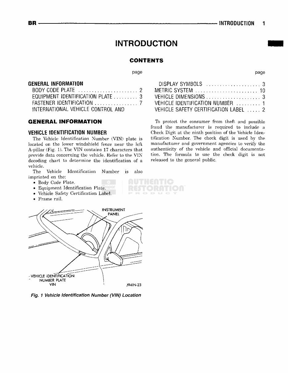
BR INTRODUCTION 1 INTRODUCTION CONTENTS page GENERAL INFORMATION BODY CODE PLATE . 2 EQUIPMENT IDENTIFICATION PLATE ......... 3 FASTENER IDENTIFICATION 7 INTERNATIONAL VEHICLE CONTROL AND page DISPLAY SYMBOLS 3 METRIC SYSTEM 10 VEHICLE DIMENSIONS 3 VEHICLE IDENTIFICATION NUMBER ......... 1 VEHICLE SAFETY CERTIFICATION LABEL ..... 2 GENERAL INFORMATION VEHICLE IDENTIFICATION NUMBER The Vehicle Identification Number (VIN) plate is located on the lower windshield fence near the left A-pillar (Fig. 1). The VIN contains 17 characters that provide data concerning the vehicle. Refer to the VIN decoding chart to determine the identification of a vehicle. The Vehicle Identification Number is also imprinted on the: • Body Code Plate. ® Equipment Identification Plate. • Vehicle Safety Certification Label. • Frame rail. To protect the consumer from theft and possible fraud the manufacturer is required to include a Check Digit at the ninth position of the Vehicle Iden- tification Number. The check digit is used by the manufacturer and government agencies to verify the authenticity of the vehicle and official documenta- tion. The formula to use the check digit is not released to the general public. Fig. 1 Vehicle Identification Number (VIN) Location
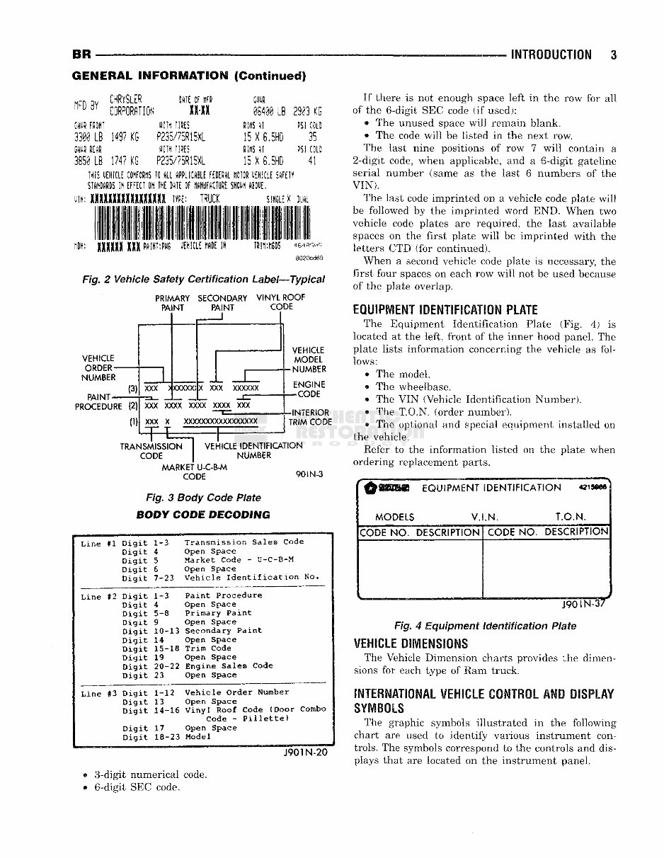
INTRODUCTION BR GENERAL INFORMATION (Continued) POSITION INTERPRETATION CODE = DESCRIPTION 1 Country of Origin 1 = United States 3 = Mexico 2 Make B = ^odge 3 Vehicle Type 4 = Multipurpose Passenger 5 = Bus 6 = Incomplete 7 = Truck 4 Gross Vehicle Weight Rating H = 6001-7000 J = 7001-8000 K = 8001-9000 L = 9001-10,000 M = 10,001-14,000 W = Hydraulic Brakes 5 Vehicle Line C = Ram Cab Chassis/Ram Pick Up (4x2) F = Ram Cab Chassis/Ram Pick Up (4x4) 6 Series 1 = 1500 2 = 2500 3 = 3500 7 Body Style 3 = Club Cab 6 = Conventional Cab Cab Chassis 8 Engine C = 5.9L 6cyl. Diesel W = 8.0L 10 cyl. MPI X = 3.9L 6 cyl. MPI Y = 5.2L 8 cyl. MPI Z = 5.9L 8 cyl. MPI-LDC 5 = 5.9L 8cyl. MPI-HDC 9 Check Digit 10 Model Year T = 1996 11 Plant Location J = St. Louis North S = Dodge City G = Saltillo M = Lago Alberto Assembly 12 thru 17 Vehicle Build Sequence VEHICLE SAFETY CERTIFICATION LABEL A certification label is attached to the left side B-pillar (Fig. 2). The label certifies that the vehicle conforms to Federal Motor Vehicle Safety Standards (FMVSS). The label also lists the: • Month and year of vehicle manufacture. • Gross Vehicle Weight Rating (GVWR). The gross front and rear axle weight ratings (GAWR's) are based on a minimum rim size and maximum cold tire inflation pressure. • Vehicle Identification Number (VIN). • Type of vehicle. • Type of rear wheels. • Bar code. • Paint Code. • Month, Day and Hour (MDH) of final assembly. BODY CODE PLATE The Body Code Plate is located on the floor pan under the passenger seat (Fig. 3). There can be a maximum of seven rows of vehicle information imprinted on the plate. The information should be read from left to right, starting with line 1 at the bottom of the plate up through line 7 (as applicable) at the top of the code plate. Refer to the decoding chart to decode lines 1 up through 3. Lines 4 through 7 (if used) on the vehicle code plate are imprinted on the plate (in sequence) accord- ing to the following: • 3-character sales code.
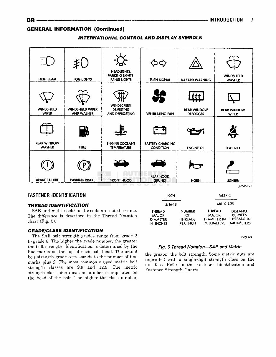
BR INTRODUCTION 3 GENERAL INFORMATION (Continued) flFD BY CHRYSLER DATE OF m CORPORATION MM G f t PR FRONT U1IH T I RES 3309 LB 149? KG P235/75R15KL m m W I TH !!KS 3850 LB 1747 KG P235/75R15XL THIS UEH I CLE COHFOP t l S !0 ALL APPL I CABLE FEDERAL I EFFECI OH THE DATE OF I xxxxxx II II! IIIII TVPE : TRUCK 88488 LB 2903 KG R I MS ft? PSI COO 15 X GiHD 35 MS ft! PSI COLD 15 X BiHD 41 TOR UEH J CLE WW yn ABOVE. SINGLE X DO H L )H: liUli HI PftIHT:PUS UEH ICLE HADE IN TIM« 4G4 B<* 5 8020cd69 Fig. 2 Vehicle Safety Certification Label—Typical PRIMARY SECONDARY VINYL ROOF PAINT PAINT CODE I VEHICLE ORDER- NUMBER PAINT- (3) PROCEDURE (2) 0) XXX > XXXXX) X XXX xxxxxx XXX xxxx xxxx xxxx XXX XXX X XXXXXXXXXXXXXXXXX VEHICLE MODEL -NUMBER ENGINE -CODE -INTERIOR TRIM CODE TRANSMISSION VEHICLE IDENTIFICATION CODE J NUMBER MARKET U-C-B-M CODE 90IN-3 Fig. 3 Body Code Plate BODY CODE DECODING Line #1 Digit 1-3 Transmission Sales Code Digit 4 Open Space Digit 5 Market Code - U-C-B-M Digit 6 Open Space Digit 7-23 Vehicle Identification No. Line #2 Digit 1-3 Digit 4 Paint Procedure Open Space Digit 5-8 Primary Paint Digit 9 Open Space Digit 10-13 Secondary Paint Digit 14 Open Space Digit 15-18 Trim Code Digit 19 Open Space Digit 20-22 Engine Sales Code Digit 23 Open Space Line #3 Digit 1-12 Vehicle Order Number Digit 13 Open Space Digit 14-16 Vinyl Roof Code CDoor Combo Code - P i l l e t t e ) Digit 17 Open Space Digit 18-23 Model J901N-20 • 3-digit numerical code. • 6-digit SEC code. If there is not enough space left in the row for all of the 6-digit SEC code (if used): • The unused space will remain blank. • The code will be listed in the next row. The last nine positions of row 7 will contain a 2-digit code, when applicable, and a 6-digit gateline serial number (same as the last 6 numbers of the VIN). The last code imprinted on a vehicle code plate will be followed by the imprinted word END. When two vehicle code plates are required, the last available spaces on the first plate will be imprinted with the letters CTD (for continued). When a second vehicle code plate is necessary, the first four spaces on each row will not be used because of the plate overlap. EQUIPMENT IDENTIFICATION PLATE The Equipment Identification Plate (Fig. 4) is located at the left, front of the inner hood panel. The plate lists information concerning the vehicle as fol- lows: • The model. • The wheelbase. • The VIN (Vehicle Identification Number). • The T.O.N, (order number). • The optional and special equipment installed on the vehicle. Refer to the information listed on the plate when ordering replacement parts. r Qmmsi EQUIPMENT !Dem¥iE^ MODELS V.I.N. \^.\. CODE NO. DESCRIPTION CODE NO. DESCRIPTION —u Fig. 4 Equipment Identification Plate VEHICLE DIMENSIONS The Vehicle Dimension charts provides the dimen- sions for each type of Ram truck. INTERNATIONAL VEHICLE CONTROL AND DISPLAY SYMBOLS The graphic symbols illustrated in the following chart are used to identify various instrument con- trols. The symbols correspond to the controls and dis- plays that are located on the instrument panel.
4 INTRODUCTION GENERAL INFORMATION (Continued) vehicle exterior dimensions—STD cab 1500/ 1500 4x4 2500/ 3500/ 3500 4x4 A Wheelbase 1 19" 135" 135" 135" e Box Length (feet) 6.5 8.0 8.0 € Ground Clearance (Empty) —Front 9.7/8.1 10.0/8.1 10.1/8.1 7 7/'. 12 € —Rear 10.1/9.8 ! 10.179J! 10.1/9.3 71 ..77 D Overall Length —Without rear bumper 199.9 220.1 220.1 220.1 D —With rear bumper 204.1 224.3 224.3 224.3 1 Overall Height (Empty) 72.1/75.9 1 72.1/75.9 73.7/78.0 7777:7 ¥ Overall Width —At Front Wheel Lip 70.4 79.4 79.4 79.5 1 8 Track —Front 68.5 68,5 68.6 63.6 8 —Rear 68.0 68.0 73.0 H Tailgate Load Height 3 72/35.6 31.5/35.6 31.5/35.6 31.4/35.6 i Overhang—Front 37.9 3^ 37.9 37.9 J Overhang—Rear —Without Rear Bumper 47.6 47.6 47.6 47.6 J —With Rear Bumper r 51.7 51.7 51.7 5 77 f€ Back Of Cab To Rear Bumper 87.2 107.4 107.4 77,- I Front Bumper To Back Of Cab " \ \ v 116.9 116.9 116.9 Approach Angle (Degrees} 25.3/29 7 25.3/29.7 25.3/29.7 1 "25.3/29.7 1 M Breakover Angle (Degrees] : 7.8/2 70 I 17.8/21.0 7-' •; : 0 Departure Angle (Degrees) 1076/35.2 ^30^56.2 1 30.6/3o.2~ 30.6/36.2 1 93.5 at cargo box. J941N-25
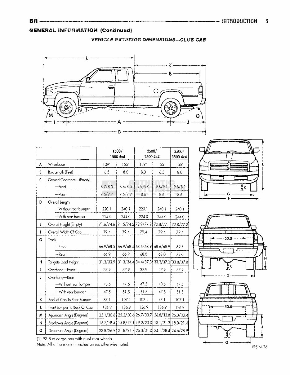
GENERAL INFORMATION (Continued) VEHICLE EXTERIOR DIMENSIONS—CLUE CAB 1500/ 15004x4 2500/ 25004x4 3500/ 3500 4x4 A Wheelbase 139" 155" 139" 155" 155" 1 Box Length (Feet) 6.5 8.0 8.0 6.5 8.0 C Ground Clearance—(Empty) —Front 87/8.5 8.6/8.5 9.9/9.0 9.8/9.1 9.8/8.1 C —Rear 7.5/7.7 7.5/7.7 8.6 8.6 8.6 D Overall Length —Without rear bumper 220.1 240.1 220.1 240.1 240.1 D —With rear bumper 224.0 244.0 224.0 244.0 244.0 E Overall Height (Empty) 71.6/74.6 7).5/74.5 72.9/77.2 72.8/77.1 72.8/77.2 f Overall Width Of Cab 79.4 79.4 79.4 79.4 79.4 G Track —?rorii 66.9/68.5 66.9/68.5 68.6/68.9 68.6/68.9 69.8 G —Rear 66.9 667 68 0 68.0 73.0 H Tailgate Load Height 31.3/33.9 31 3/34.4 34.4/37.3 33.3/37.2 33.8/37.8 I Overhang—Front 37.9 37.9 37.9 37.9 37.9 J Overhang;— Rear —Without rear bumper .a.s 47.5 A7.5 43.5 5 J —With rear bumper 475 51.5 51.5 47.5 51.5 K Back of Cab To Rear Bumper 87.1 107.1 ! 107.1 87.1 ' 107.1 L Front Bumper To Back Of Cab 136.9 136.9 •; 36.9 136.9 136/' M Approach Angle (Degrees) 25.1/30.6 25.2/30.6 .267/33.7 26.8/33.8 26.3/33/ N Breakover Angle (Degrees) 16.7/18.4 15.8/17.1 19.2/23.0 18.1/21.3 18.0/2i/i 0 Depariure Angle (Degrees) 23.8/26.9 21.8/247 26.0/31.0 24.1/28.4 24.6/28.9 (1) 93.3 at cargo box with dual-rear wheels. Note: All dimensions in inches unless otherwise noted. J95IN-26
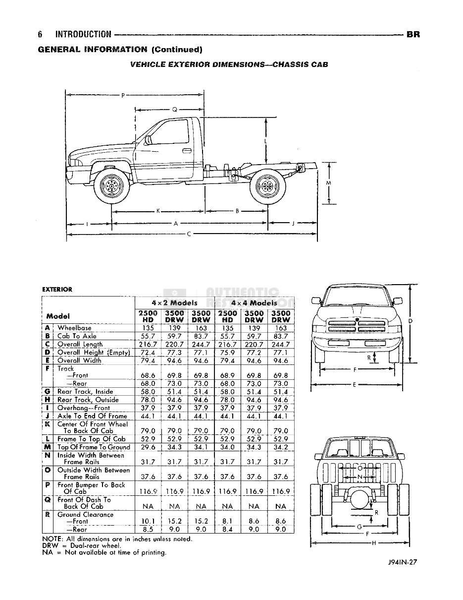
6 INTRODUCTION — GENERAL INFORMATION (Continued) VEHICLE EXTERIOR DIMENSIONS—CHASSIS CAB BR EXTERIOR Model 4x2 Models 4x4 models Model HD mm mw 35§§ mw 2500 HD 3500 DRW 3500 mw A Wheelbase 135 139 163 135 139 163 i Cab To Axle 55.7 59.7 83.7 55.7 59.7 83.7 C Overall Length 216.7 220.7 244.7 216.7 220.7 244.7 D Overall Height (Empty) 72.4 77.3 77.1 75.9 77.2 77.1 E Overall Width . 79.4 94 .6 94 .6 79.4 94 .6 94.6 F Track —Front 68 .6 69.8 69.8 68.9 69.8 69.8 F —Rear 68.0 73.0 73.0 68.0 73.0 73.0 G Rear Track, Inside 58.0 51.4 51.4 58.0 51.4 51.4 H Rear Track, Outside 78.0 94 .6 94.6 78.0 94 .6 94.6 1 Overhang—Front 37.9 37.9 37.9 37.9 37.9 37.9 J Axle To End Of Frame 44 .1 44.1 44.1 44 .1 44.1 44.1 K Center Of Front Wheel To Back Of Cab 79.0 79.0 79.0 79.0 79.0 79.0 L Frame To Top Of Cab 52.9 52.9 52.9 52.9 52.9 52.9 M Top Of Frame To Ground 29 .6 34.3 34.1 34.0 34.3 34.2 N Inside Width Between Frame Rails 31.7 31.7 31.7 31.7 31.7 31.7 O Outside Width Between Frame Rails 37 .6 37 .6 37 .6 37 .6 37 .6 37 .6 P Front Bumper To Back Of Cab 116.9 116.9 116.9 116.9 116.9 116.9 Q Front Of Dash To lack Of Cab NA NA NA NA NA NA R Ground Clearance —Front 10.1 15.2 15.2 8.1 8.6 8.6 R —Rear 8.5 9.0 9.0 8.4 9.0 9.0 inches unless noted. NOTE: All dimensions are in DRW = Dual-rear wheel. NA = Not available at time of printing. / n n anr/3HD n n \ J94IN-27
This professional technical manual contains service, maintenance, and troubleshooting information for your Dodge Ram 1500 Series 1996 1997, covering all models, engines, trim, and transmission types. It is useful for both professional mechanics and DIY enthusiasts.
The Dodge Ram 1500 Series 1996 1997 workshop repair service manual is complete and intact, containing hundreds of pages of diagrams and detailed information for specific vehicle or equipment repair. It includes:
Dodge Ram 1500 Series 1996 1997 General Maintenance
Dodge Ram 1500 Series 1996 1997 Troubleshooting
Dodge Ram 1500 Series 1996 1997 Engine Service/Repair
Dodge Ram 1500 Series 1996 1997 Transmission Service/Repair
And more...
The manual also features detailed substeps, notes, cautions, warnings, numbered instructions, illustrations, and photos to guide you through every procedure. It is available in English and can be zoomed in/out. The file format is .PDF, making it easy to diagnose and repair problems with your machine's electrical system.
Having the manual in an electronic format is advantageous, allowing you to print the desired section from your PC and dispose of it after completing the repair or service. Whether using a paper manual or electronic version, you'll find the same features in both. This Dodge Ram 1500 Series 1996 1997 workshop repair service manual includes step-by-step repair procedures, critical specifications, illustrations, maintenance, disassembly, assembly, cleaning, and reinstalling procedures.
With this professional quality, highly detailed Dodge Ram 1500 Series 1996 1997 service repair workshop manual, you will have the best resources available to work on your vehicle, saving you money in repair costs and helping you look after your Dodge Ram 1500 Series 1996 1997.
Product Details:
File Format: .PDF
Language: English
Specifications: Full Printable
Zoom IN/OUT: Yes
Delivery: Instant
Requirements: Adobe Reader & Win
Compatible: All Versions of Windows & Mac
Recently Viewed
5,521,897Happy Clients
2,594,462eManuals
1,120,453Trusted Sellers
15Years in Business
Price:
Actual Price:
1996-1997 Dodge Ram 1500 Series Service & Repair Manual