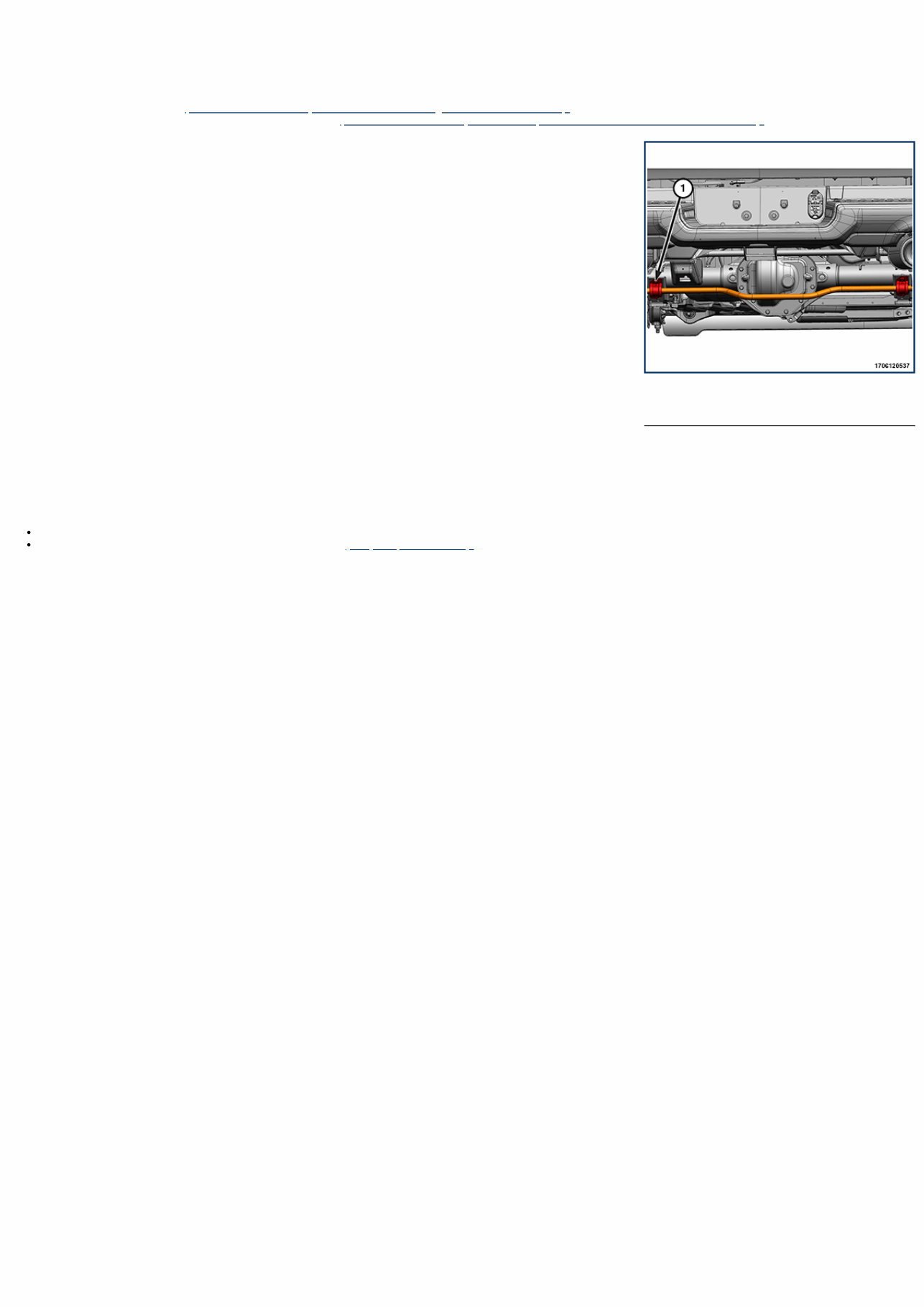
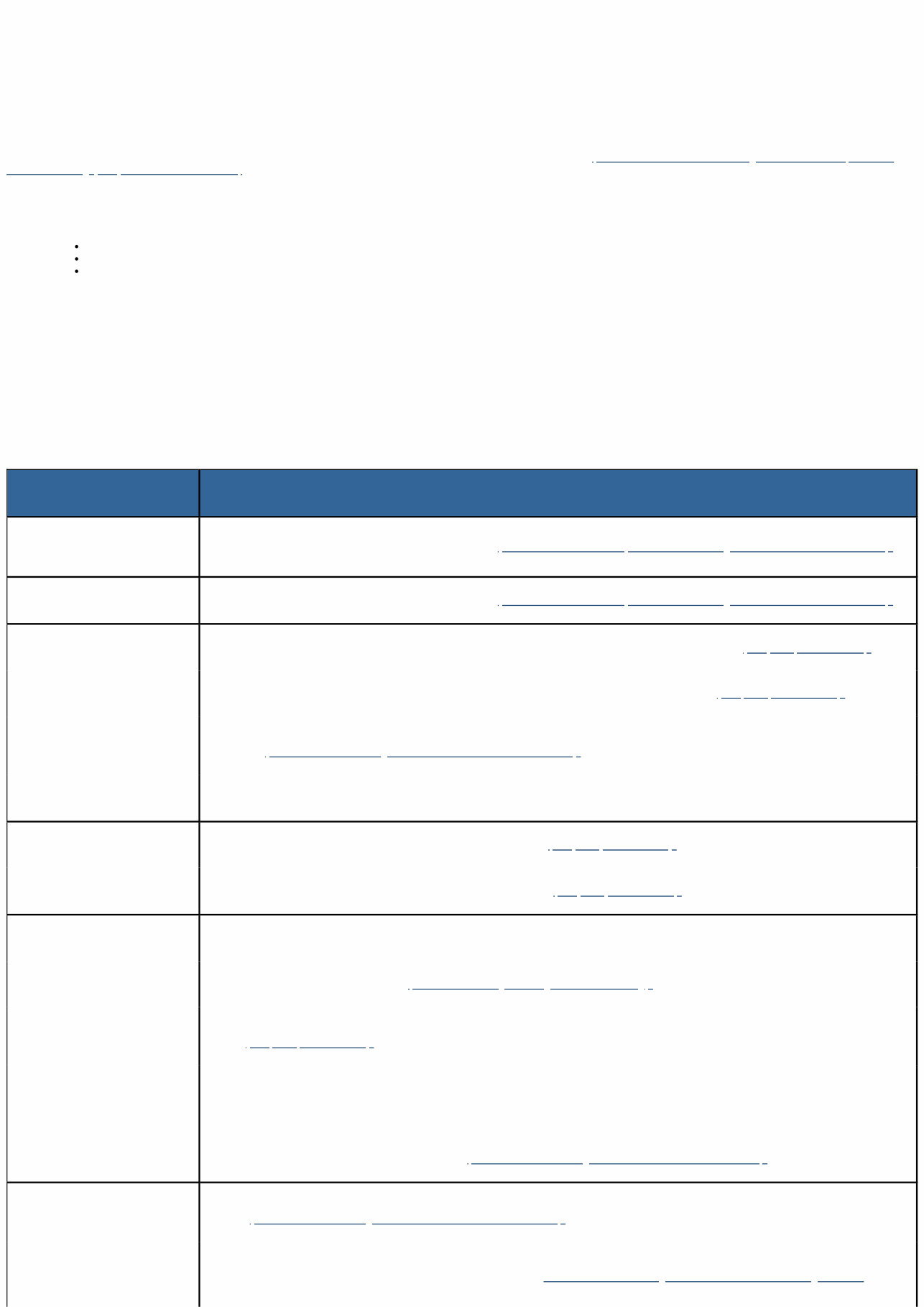
1 - Stabilizer Bar Bolts 17 - Rear Suspension / STABILIZER BAR, Rear Suspension / Removal and Installation REAR SUSPENSION STABILIZER BAR REMOVAL 1. Raise and support vehicle (Refer to 04 - Vehicle Quick Reference/Hoisting - Standard Procedure) . 2. Disconnect both stabilizer links from the stabilizer bar (Refer to 17 - Rear Suspension/LINK, Stabilizer Bar/Removal and Installation) . 3. Remove the stabilizer bar bolts. 4. Remove stabilizer bar, bushings, and brackets as an assembly. 5. Remove the stabilizer bar brackets from the bushings. 6. Remove the stabilizer bar bushings from the stabilizer bar. INSTALLATION Follow the removal procedure in reverse for general reassembly of the components on the vehicle. The steps listed below are calling out specific procedures that should be followed during installation. Position the stabilizer bar assembly to the axle and center it with equal spacing on both sides. Install the stabilizer bar bolts and tighten to the proper (Torque Specifications) .
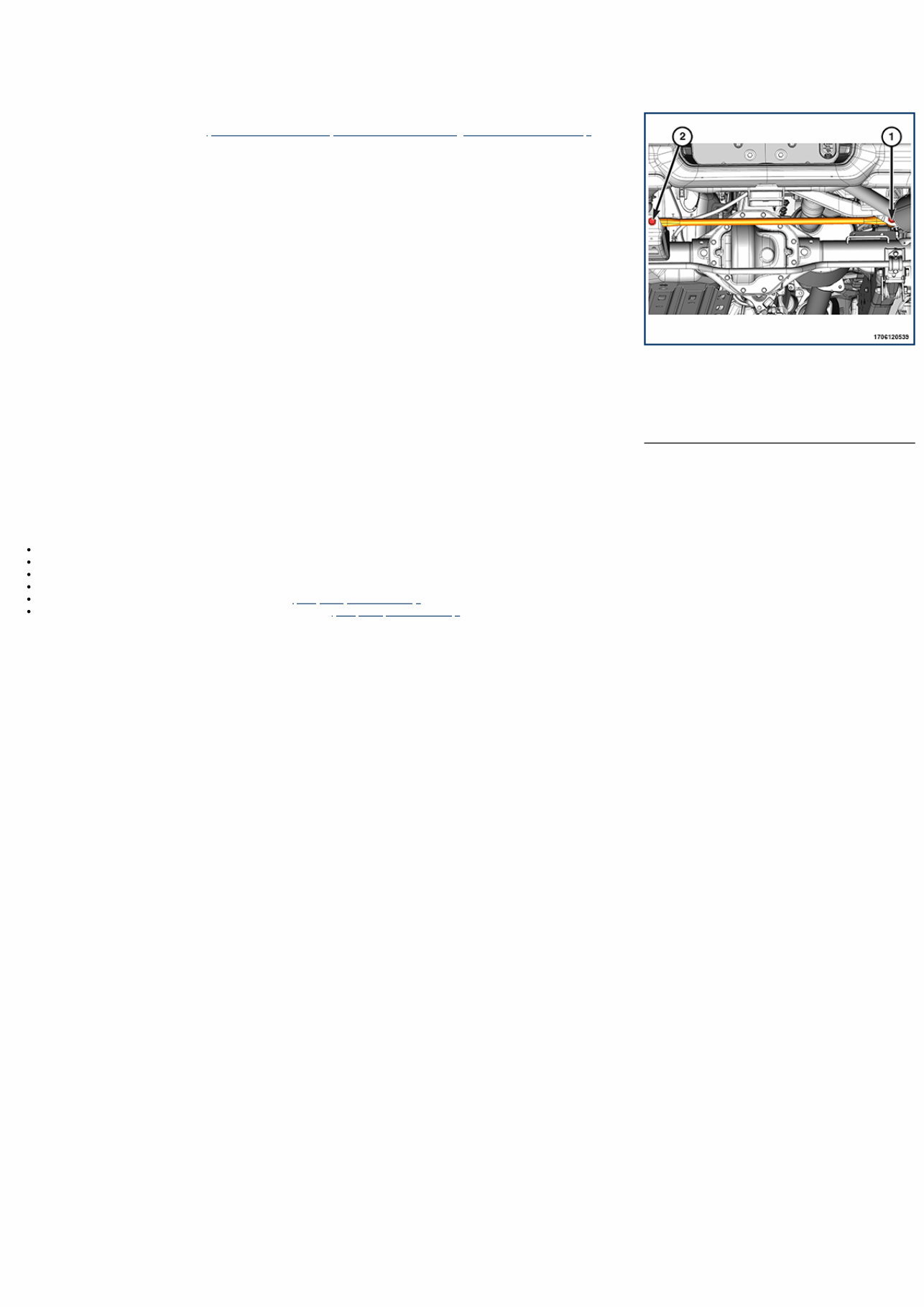
1 - Track Bar Frame Bolt 2 - Track Bar Axle Bolt 17 - Rear Suspension / TRACK BAR, Rear / Removal and Installation REAR TRACK BAR WITHOUT TRX REMOVAL 1. Raise and support the vehicle (Refer to 04 - Vehicle Quick Reference/Hoisting - Standard Procedure) . 2. Support the rear axle with a suitable holding fixture. 3. Remove the track bar frame bolt and DISCARD the nut and bolt. 4. Remove the track bar axle bolt and DISCARD the nut and bolt. 5. Remove the track bar. INSTALLATION Follow the removal procedure in reverse for general reassembly of the components on the vehicle. The steps listed below are calling out specific procedures that should be followed during installation. In any instance where a bolt is through a rubber bushing, the bolt must be torqued with the vehicle at normal ride height. Install a NEW track bar axle bolt and a NEW nut but do not tighten at this time. The rear axle assembly may need to be shifted to one side in order to install upper track bar bolt. Install a NEW track bar frame bolt and a NEW nut but do not tighten at this time. Tighten the track bar frame nut to the proper (Torque Specifications) . Tighten the track bar axle bolt and nut to the proper (Torque Specifications) .
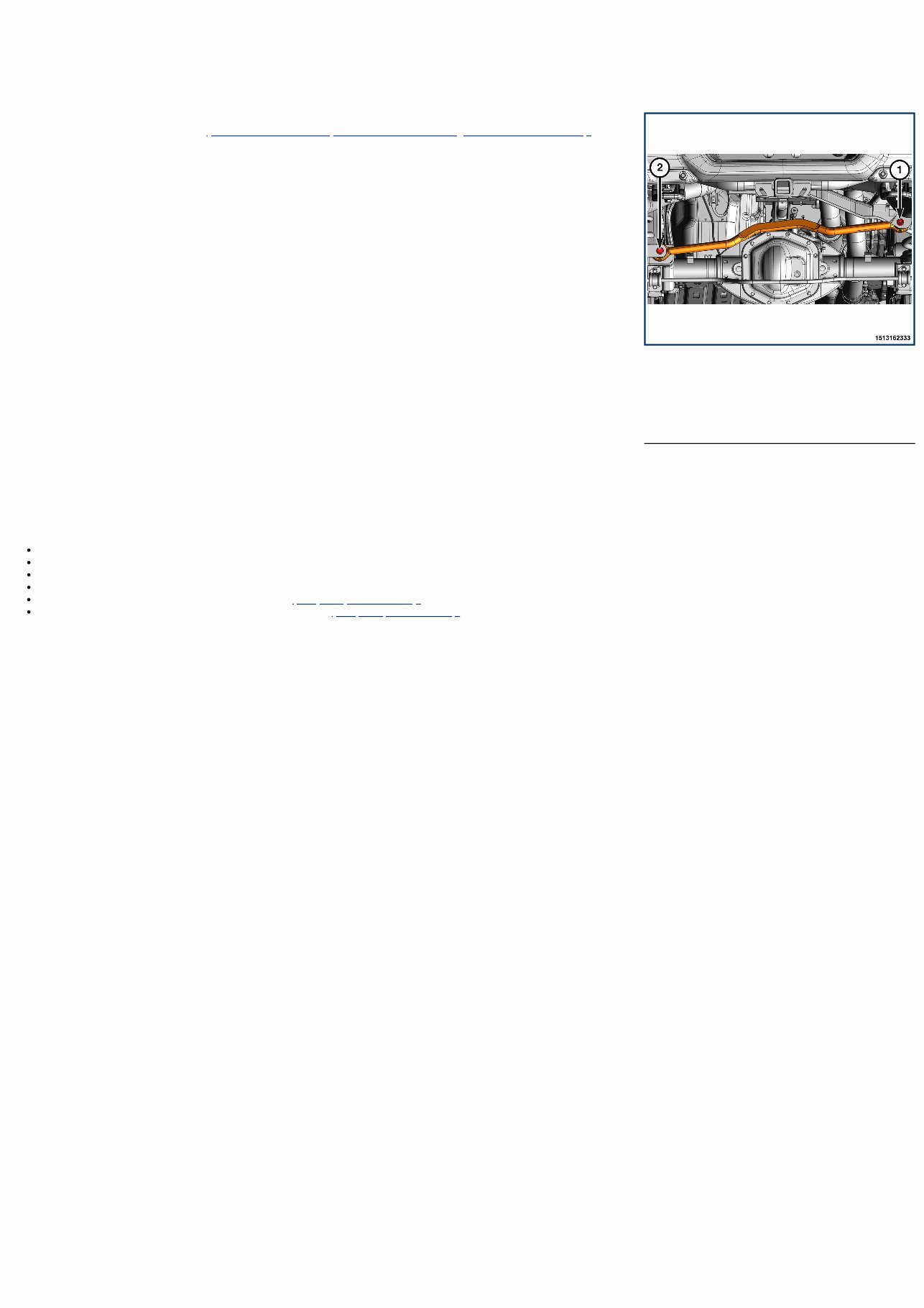
1 - Track Bar Frame Bolt 2 - Track Bar Axle Bolt 17 - Rear Suspension / TRACK BAR, Rear / Removal and Installation REAR TRACK BAR WITH TRX REMOVAL 1. Raise and support the vehicle (Refer to 04 - Vehicle Quick Reference/Hoisting - Standard Procedure) . 2. Support the rear axle with a suitable holding fixture. 3. Remove the track bar frame bolt and DISCARD the nut and bolt. 4. Remove the track bar axle bolt and DISCARD the nut and bolt. 5. Remove the track bar. INSTALLATION Follow the removal procedure in reverse for general reassembly of the components on the vehicle. The steps listed below are calling out specific procedures that should be followed during installation. In any instance where a bolt is through a rubber bushing, the bolt must be torqued with the vehicle at normal ride height. Install a NEW track bar axle bolt and a NEW nut but do not tighten at this time. The rear axle assembly may need to be shifted to one side in order to install upper track bar bolt. Install a NEW track bar frame bolt and a NEW nut but do not tighten at this time. Tighten the track bar frame nut to the proper (Torque Specifications) . Tighten the track bar axle bolt and nut to the proper (Torque Specifications) .
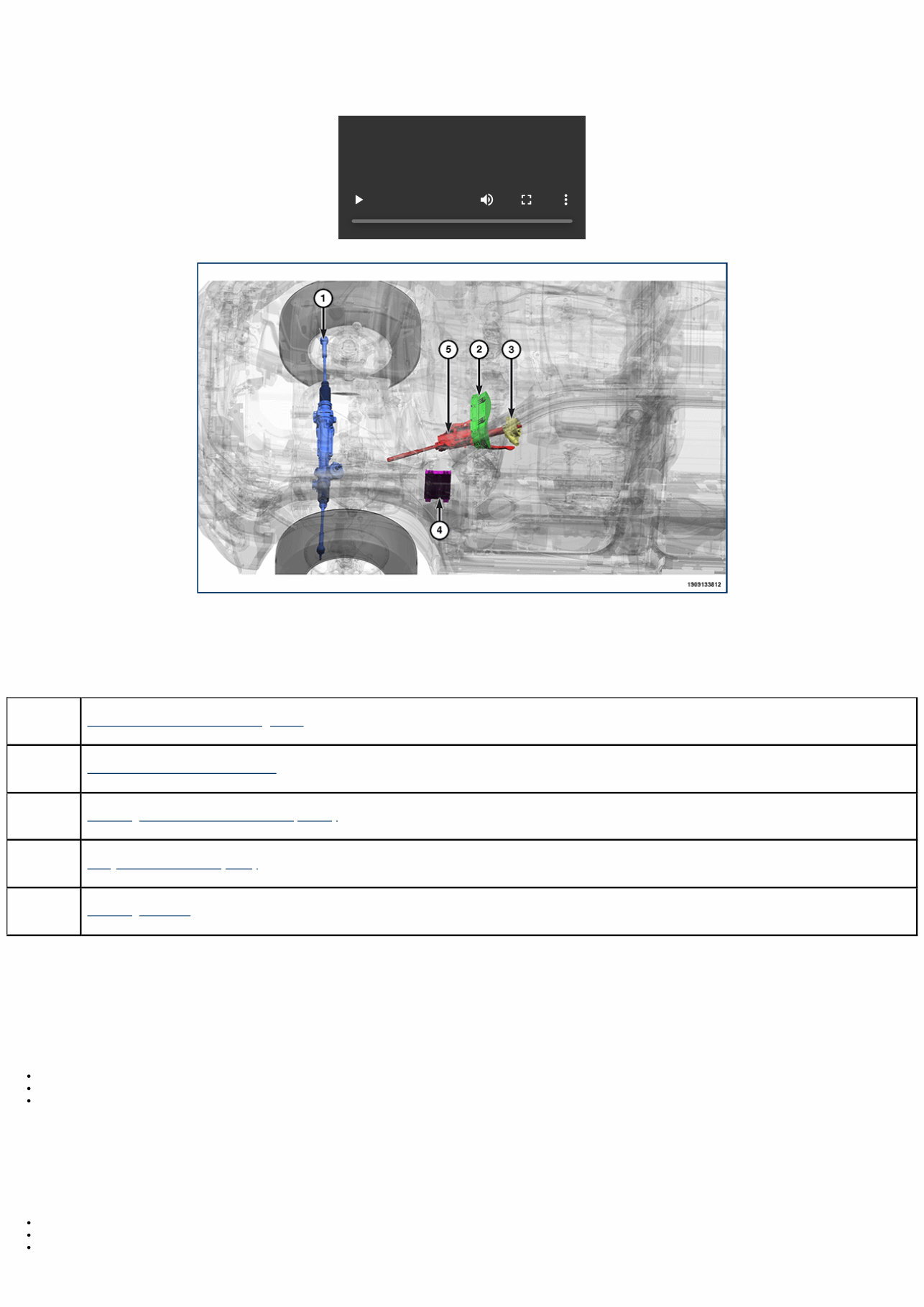
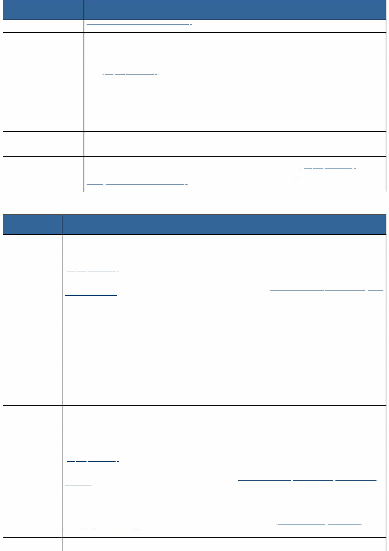
19 - Steering / Description DESCRIPTION DESCRIPTION The Electric Power Steering (EPS) consists of the following components: Component Index 1. EPS Rack and Pinion Steering Gear 2. Instrument Panel Cluster (IPC) 3. Steering Column Control Module (SCCM) 4. Body Control Module (BCM) 5. Steering Column OPERATION The standard equipment EPS system provides variable assist to the driver according to driver inputs and the vehicle speed while performing system diagnostic tests and providing this information to the vehicle electrical system. The SCCM has a Steering Angle Sensor (SAS) which transmits the direction and the angle information on the Controller Area Network-Chassis (CAN-C) or Controller Area Network-Interior High Speed (CAN-IHS) bus networks. The SCCM has primary and backup microprocessors with different software algorithms that provide Cyclical Redundancy Checks (CRC) to confirm the SAS position. The EPS warning lamp is used to visually indicate a fault status of the EPS system to the IPC. The EPS system is a dry gear system. The EPS system does not contain any hydraulic components such as: Belt-driven hydraulic pump. High-pressure hydraulic hoses. Power steering fluid. The EPS system will not experience a hydraulic leak. If fluid is detected at the front of the vehicle, on or near the steering gear, investigate other systems. Turning of the steering wheel is converted into linear (side-to-side) travel through the meshing of the helical pinion teeth with the rack teeth within the steering gear. The lateral travel pushes and pulls the tie rods to change the direction of the vehicle's front wheels. Power assist steering is provided by an electric motor and module connected to the steering gear. The EPS system provides variable assist for steering maneuvers based on several inputs: Steering wheel position and rate of movement from SAS. Steering wheel torque from torque sensors in the EPS rack and pinion steering gear. Vehicle speed received from the Anti-lock Brake System (ABS) module. 0:00
The EPS rack and pinion steering gear is not serviceable and is replaced as a complete assembly. The inner and outer tie rods and the tie rod bellows are serviced separately from the EPS rack and pinion steering gear. Manual steering control of the vehicle can be maintained if power steering assist is lost. However, under this condition, steering effort is significantly increased. Body Control Module (BCM) Component Index The BCM receives the following: CAN-C INPUTS Steering wheel angle. Steering wheel angle sensor status. EPS mode status. Power steering system type. EPS warning display request. The BCM provides the following: CAN-C OUTPUTS Vehicle configuration data. Commanded ignition switch status. System voltage. EPS module type. CAN-IHS OUTPUTS Steering wheel angle. Steering wheel angle sensor status. EPS mode status. EPS warning display request. Power steering system type. EPS Rack and Pinion Steering Gear Component Index The EPS rack and pinion steering gear consists of the following components: Electric motor. EPS module. Internal steering torque sensor. Rack and pinion gear. If any of the components need to be replace, the EPS rack and pinion steering gear is replaced as a complete assembly. The EPS rack and pinion steering gear receives the following: CAN-C INPUTS Steering wheel angle. Delta steering wheel angle. Steering wheel angle sensor status. Vehicle longitudinal acceleration. Vehicle lateral acceleration. ESS engine status. Drivers Assistance Module (DASM) torque overlay steering request. Hybrid propulsion system active. Transmission gear. STOP/START feature present. Vehicle speed. Wheel Revolutions Per Minute (RPM) front left. Wheel Revolutions Per Minute (RPM) front right. Commanded ignition switch status. Engine RPM. System voltage. EPS module type. Vehicle configuration data. The EPS rack and pinion steering gear provides the following: CAN-C OUTPUTS EPS warning display request. Engine fan activation request for cooling. EPS mode status. Power steering system type. EPS assistance status. EPS current. Torque provided by EPS to the steering shaft. Steering column torque. Steering column torque valid data. Instrument Panel Cluster (IPC)
Component Index The IPC receives the following: CAN-C INPUTS EPS module present. EPS warning display request. Commanded ignition state. Steering Column Component Index The steering column has been designed to be serviced as an assembly; less wiring, switches, shrouds, steering wheel, etc. Most steering column components can be serviced without removing the steering column from the vehicle. The adjustable pedal switch is mounted on the left side of the steering column below the multi- function switch and the ignition switch is mounted to the instrument panel. Steering Column Control Module (SCCM) Component Index The SCCM combines the following components in a single assembly: Clockspring. Multifunction switch. Steering angle sensor. The SCCM receives the following: CAN-C INPUTS Steering position. Commanded ignition switch status. System voltage. The SCCM provides the following: CAN-C OUTPUTS Steering wheel angle. Delta steering wheel angle. Steering wheel angle sensor status. Steering wheel angle remainder high precision. Steering angle polarity.
19 - Steering / Diagnosis and Testing DIAGNOSIS AND TESTING - STEERING SYSTEM NOTE: Verify the correct software and calibration files are loaded in the Electric Power Steering (EPS) system. If any EPS DTCs are present, perform the appropriate diagnostic procedure before continuing (Refer to 28 - DTC-Based Diagnostics/MODULE, Electric Power Steering (EPS) /Standard Procedure). NOTE: The EPS system is a dry gear system. The EPS system does not contain any hydraulic components such as: Belt-driven hydraulic pump. High-pressure hydraulic hoses. Power steering fluid. The EPS system will not experience a hydraulic leak. If fluid is detected at the front of the vehicle, on or near the steering gear, investigate other systems. NOTE: The EPS gear may have residual grease from the supplier for water intrusion prevention purposes and does not constitute failure of the EPS gear. MECHANICAL PERFORMANCE ISSUES CONDITION EVALUATION/CORRECTION STEERING WHEEL IS OFF CENTER 1 . Perform the wheel alignment standard procedure (Refer to 02 - Front Suspension/Wheel Alignment - Standard Procedure) . VEHICLE PULLS LEFT OR RIGHT 1 . Perform the wheel alignment standard procedure (Refer to 02 - Front Suspension/Wheel Alignment - Standard Procedure) . PERCEIVED COLUMN/STEERING WHEEL FREE PLAY 1. Check pinch bolt torque. Replace pinch bolt with thread locker patch and tighten to the proper (Torque Specifications) . 2. Check steering gear mounting bolt torque. Replace if necessary and tighten to the proper (Torque Specifications) . 3. Rotate the steering wheel back-and-forth while watching the coupling. Observe free-play. Replace steering column as necessary (Refer to 19 - Steering/Column/Removal and Installation) . 4. If the issue remains despite previous steps, perform further evaluation of the steering joints. STEERING WHEEL HAS FORE AND AFT LOOSENESS 1. Check steering wheel bolt torque and tighten to the proper (Torque Specifications) . 2. Check steering column nut torque and tighten to the proper (Torque Specifications) . PERCEIVED DASH, VEHICLE, STEERING WHEEL VIBRATION BY DRIVER 1. Check tire pressure. Inflate tires to specified pressure if necessary. 2. Verify engine tuning/performance (Refer to 09 - Engine/Diagnosis and Testing) . 3. Check the torque of the tie rod jam nut, tie rod end to knuckle nut, and steering gear mounting bolts, and tighten to the proper (Torque Specifications) . 4. Visually inspect for damaged or misaligned mounts. Check fastener torque. Replace or realign as necessary. 5. While the vehicle is still at 0 mph, turn the steering wheel end lock to end lock to verify if there is vibration only while steering. Steer in both directions and verify that the noise/vibration follows the steering input. Check TSBs for any known issues. Replace the steering gear as necessary (Refer to 19 - Steering/Gear/Removal and Installation) . DIFFICULT STEERING BOTH DIRECTIONS 1. Disconnect the intermediate shaft and rotate the steering column. If the condition is still present, replace the steering column (Refer to 19 - Steering/Column/Removal and Installation) . 2. Verify that the steering column intermediate shaft bearing is installed with the Pentastar stamping up. Inspect the steering column intermediate shaft bearing and replace as necessary (Refer to 19 - Steering/Column/BEARING, Steering Column
CONDITION EVALUATION/CORRECTION Intermediate Shaft/Removal and Installation) . STEERING CATCHES/STICKS 1. Refer to “DIFFICULT STEERING BOTH DIRECTIONS”. Then review TSBs for a recent posting. If issue not resolved, proceed through the following: 2. Check the torque of the tie rod jam nut, tie rod end to knuckle nut, and steering gear mounting bolts, and tighten to the proper (Torque Specifications) . 3. Visually inspect for damaged or misaligned mounts. Check fastener torque. Replace or realign as necessary. 4. With vehicle on hoist, tires unsupported and engine on, steer gear end lock to end lock and check for smooth operation. Replace steering gear if steering efforts are not consistent throughout travel (only after all previous components have been checked). STEERING WHEEL DOES NOT RETURN TO CENTER POSITION 1. Refer to recent TSBs, followed by “VEHICLE PULLS LEFT/RIGHT”, then “DIFFICULT STEERING BOTH DIRECTIONS”, then “STEERING CATCHES/STICKS”. EXCESSIVE ROAD FEEDBACK 1. Check steering gear mounting bolt torque. Replace if necessary and tighten to the proper (Torque Specifications) . If the issue remains, rotate steering wheel back-and-forth while inspecting intermediate shaft going into the steering gear. Look for excessive free-play. Retighten if loose bolt is found. Replace steering column if necessary (Refer to 19 - Steering/Column/Removal and Installation) . NOISE, VIBRATION, AND HARSHNESS (NVH) ISSUES CONDITION EVALUATION/CORRECTION RATTLE 1. Refer to recent TSBs. If procedures outlined do not fix issue, proceed through the following: 2. Check the torque of the tie rod jam nut, tie rod end to knuckle nut, and steering gear mounting bolts, and tighten to the proper (Torque Specifications) . 3. If torque was adjusted on the steering gear mounting bolts, perform wheel alignment (Refer to 02 - Front Suspension/Wheel Alignment - Standard Procedure) . 4. Visually inspect for damaged or misaligned mounts. Check fastener torque. Replace or realign as necessary. 5. Visually inspect wheel mounting bolts for damage or loosen. Check torque. Replace or torque to specification as necessary. 6. Review the stabilizer bar links for damage, looseness, or deformities. Replace and torque to specification as necessary. 7. Rotate the intermediate (steering) shaft in relationship to gear, checking for free-play. Check the steering column nuts and tighten to specifications as necessary. 8. Inspect the cradle/crossmember for cracks or other damage. Replace as necessary. EXCESSIVE CLUNK 1. Refer to recent TSBs. If the procedures outlined do not fix issue, proceed through the following: 2. Inspect stabilizer bar links for damage, looseness, or deformities. Replace and torque to specification as necessary. 2. Check the torque of the tie rod jam nut, tie rod end to knuckle nut, and steering gear mounting bolts, and tighten to the proper (Torque Specifications) . 4. If torque was adjusted on EPS gear assembly, perform wheel alignment (Refer to 02 - Front Suspension/Wheel Alignment - Standard Procedure) . 5. Visually inspect for damaged or misaligned mounts. Check fastener torque. Replace or realign as necessary. 6. If issue remains despite previous steps, perform further evaluation in the steering joints (Refer to 19 - Steering/Gear/TIE ROD, Steering/Diagnosis and Testing) . POPPING 1. Refer to recent TSBs. If procedures outlined do not fix issue, proceed through the following:
CONDITION EVALUATION/CORRECTION 2. Visually inspect for damaged or misaligned mounts. Check fastener torque. Replace or realign as necessary. 3. Make sure the coupling is fully seated on gear input shaft. Retighten or re-seat as necessary. 5. If the previous steps did not fix the issue (Refer to 03 - Differential and Driveline/Diagnosis and Testing) . 4. If issues remain despite previous steps, perform further evaluation in the steering joints (Refer to 19 - Steering/Gear/TIE ROD, Steering/Diagnosis and Testing) . SQUEAKING/RUBBING 1. Refer to recent TSBs. If procedures outlined do not fix issue, proceed through the following: 2. While turning the steering wheel, check interference between moving components. Move, realign, or replace shrouds or shaft as necessary. 3. Remove the clockspring and reinstall steering wheel for testing. If noise is gone, replace the clockspring. 4. Remove the boot seal and recheck for noise. Lubricate the seal as necessary. 5. While a helper turns the steering wheel, use an electronic listening tool to determine which front suspension joint produces the noise. Replace as necessary. SCRUBBING/KNOCKING 1. Refer to recent TSBs. If procedures outlined do not fix issue, proceed through the following: 2. Verify the size tire or wheel installed is compatible with the original equipment size. 3. Drive the vehicle, moving accelerator pedal rapidly up and down attempting to locate noise. Try in both forward and reverse. Replace mounts as necessary. 4. Make sure the wheel house is properly positioned. If not, reposition as necessary. Check for bent or misaligned components. Correct or replace as necessary.
The 2023 RAM 1500 Pickup Service & Repair Manual Is A Comprehensive Guide For Fixing Issues On Your Vehicle. This Manual Provides Step-By-Step Instructions, Clear Images, And Exploded-View Illustrations For Every Troubleshooting And Replacement Procedure Recommended By The Manufacturer. The Durability Of Your Vehicle Is Unquestionable, But Regular Maintenance Is Necessary To Ensure Its Longevity. With Time, Some Parts Will Wear Out And Need To Be Replaced, And This Manual Will Provide You With All The Necessary Information To Do So.
With The Help Of This Repair Manual, You Can Save On Repairs, Increase Your Vehicle'S Reliability, And Keep The Repair Shop At Bay. No Need To Flip Through Hundreds Of Pages To Find Specific Information. The Manual Contains All The Troubleshooting Charts And Replacement Procedures Recommended By The Manufacturer, Making It Easier For You To Fix Your Vehicle. Plus, With The Ability To Carry It Around, Search, Screenshot, And Bookmark Information, This Manual Is More Convenient Than A Traditional Bound Manual.
In Addition, The 2023 RAM 1500 Pickup Service & Repair Manual Is Printable And Compatible With Various Electronic Devices, Including Pc And Mac Computers, Android And Apple Smartphones And Tablets. All You Need Is Adobe Reader, Which Is Available For Free. So Whether You Prefer A Physical Copy Or A Digital Version, This Manual Has Got You Covered.
Reviews
Q&A
Recently Viewed
5,521,897Happy Clients
2,594,462eManuals
1,120,453Trusted Sellers
15Years in Business
Price:
Actual Price:
2023 RAM 1500 Pickup 3.6L V6 24v VVT ETorque UPG I Service & Repair Manual