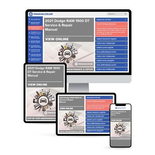
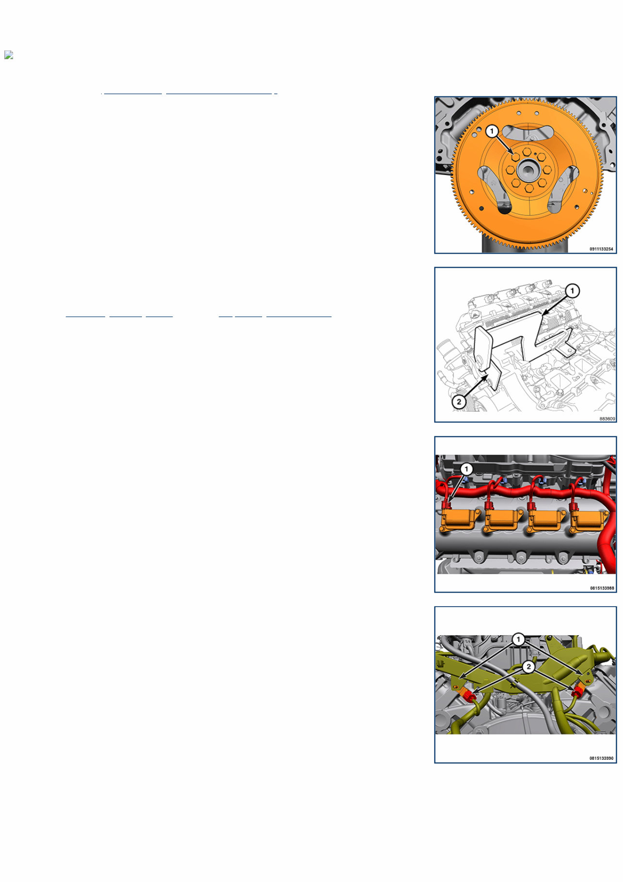
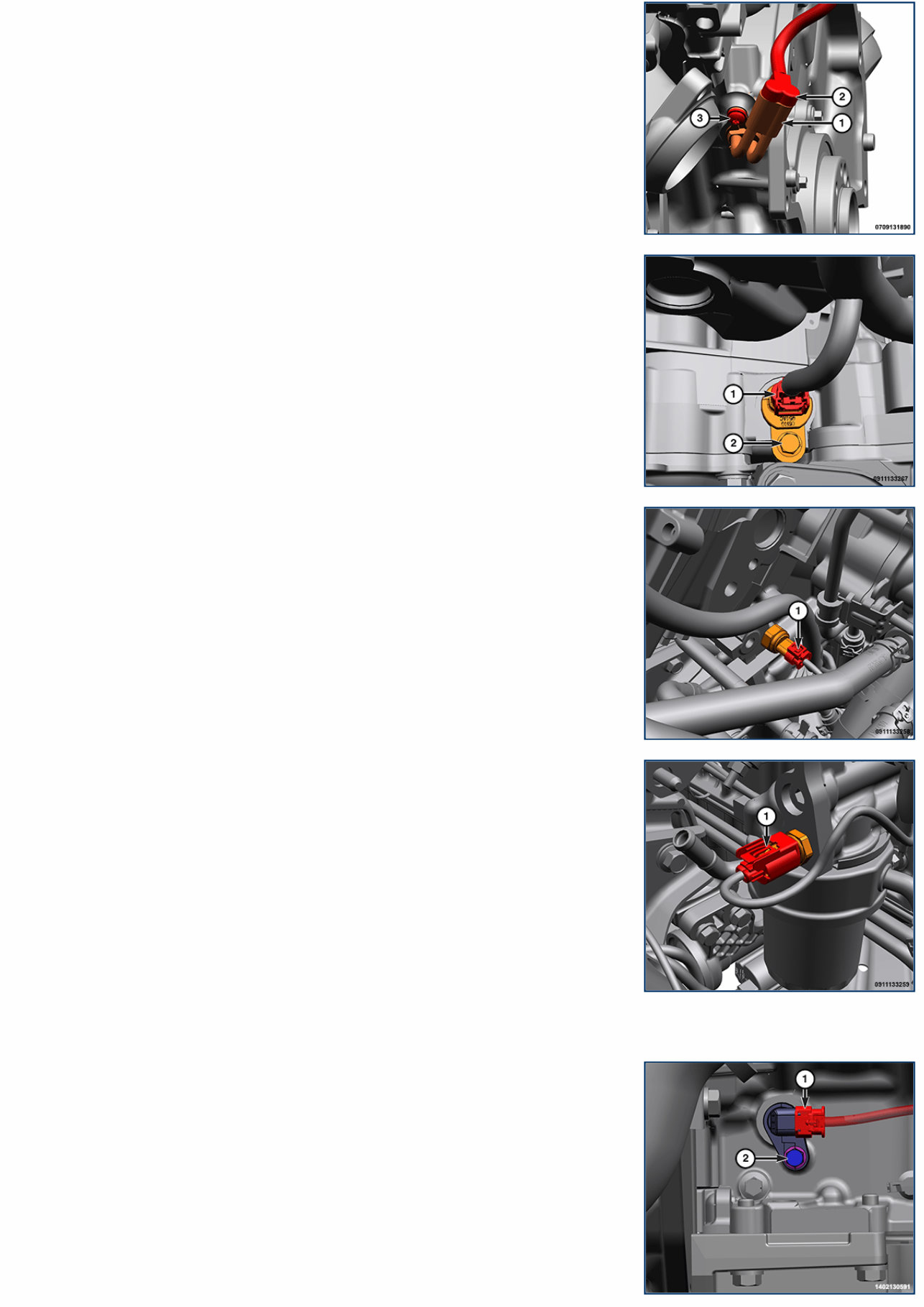
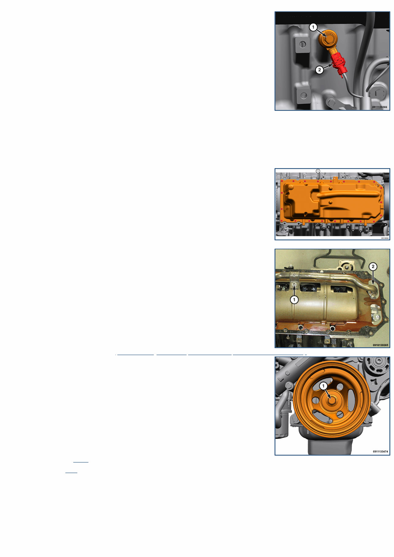
09 - Engine, 5.7L / Standard Procedure LONG BLOCK REPLACEMENT Special Tools: Click to display a list of tools used in this procedure REMOVAL 1. Remove the engine (Refer to 09 - Engine/Removal and Installation) . 2. Using a crisscross pattern, remove the bolts (1) and the flexplate. 3. Uncreate the NEW engine and mount on engine stand. NOTE: Do not use air tools to install Engine Lift Fixture (1) and Adapter (2). 4. Install the Fixture, Engine Lifting 8984C (1) and the Adapter, Engine Lift 8984-UPD (2) and securely tighten the bolts. 5. Disconnect the left side and right side ignition coil wire harness connector (1). 6. Detach the three wire harness retainers from the left cylinder head cover. 7. Disconnect the left and right ignition capacitor wire harness connector (2). 8. Remove the two fasteners securing the wire harness to the back of the cylinder heads. 9. Remove the bolt (3) and the engine block heater (1).
10. Detach the four wire harness retainers from the right cylinder head cover. 11. Disconnect the Camshaft Position Sensor (CMP) sensor wire harness connector (1). 12. Disconnect the oil pressure sensor wire harness connector (1). 13. Disconnect the oil temperature sensor wire harness connector (1). 14. Remove the lower heater hose to oil cooler. 15. Remove the lower radiator hose from the water pump. 16. Remove the fastener securing the coolant hose from oil cooler to timing cover. 17. Remove the coolant hose from the timing cover. 18. Remove the coolant hose from the oil cooler.
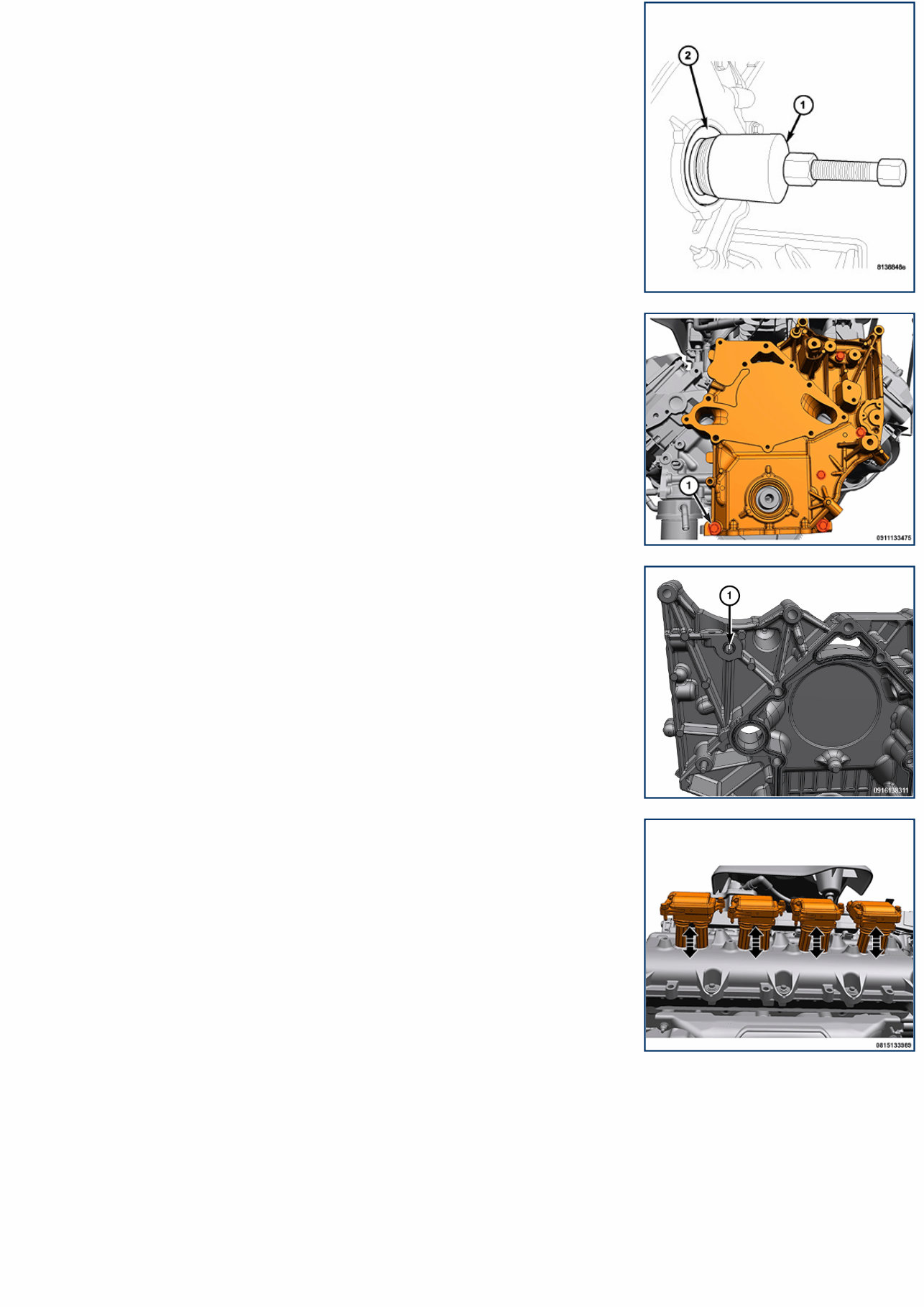
Left side shown, right side similar 19. Disconnect the Crankshaft Position (CKP) wire harness connector (1). 20. Disconnect the right knock sensor wire harness connector (2). 21. Detach the two CMP wire harness retainers from the engine block. 22. Detach the two wire harness retainers from the right cylinder head. 23. Remove the engine wire harness from the engine. 24. Remove the bolts and the left engine mount. 25. Remove the bolts and the right engine mount. 26. Remove the water pump stretchy belt. 27. Remove the oil dipstick tube. NOTE: Do not pry on oil pan or oil pan gasket. The gasket is integral to engine windage tray and does not come out with oil pan. 28. Remove the bolts (1) and the oil pan. 29. Clean the oil pan sealing surface. 30. Remove the nut (1), bolt (2) and the oil pump pickup tube. 31. Remove the appropriate belt tensioner(s) (Refer to 09 - Engine/Accessory Drive/TENSIONER, Belt/Removal and Installation) . 32. Remove the vibration damper bolt (1). 33. Using Crankshaft Insert 8513B and a commercially available puller, remove the vibration damper. 34. Using Seal Remover 9071 (1), remove the crankshaft front oil seal (2). 35. Clean the area around the front crankshaft oil seal.
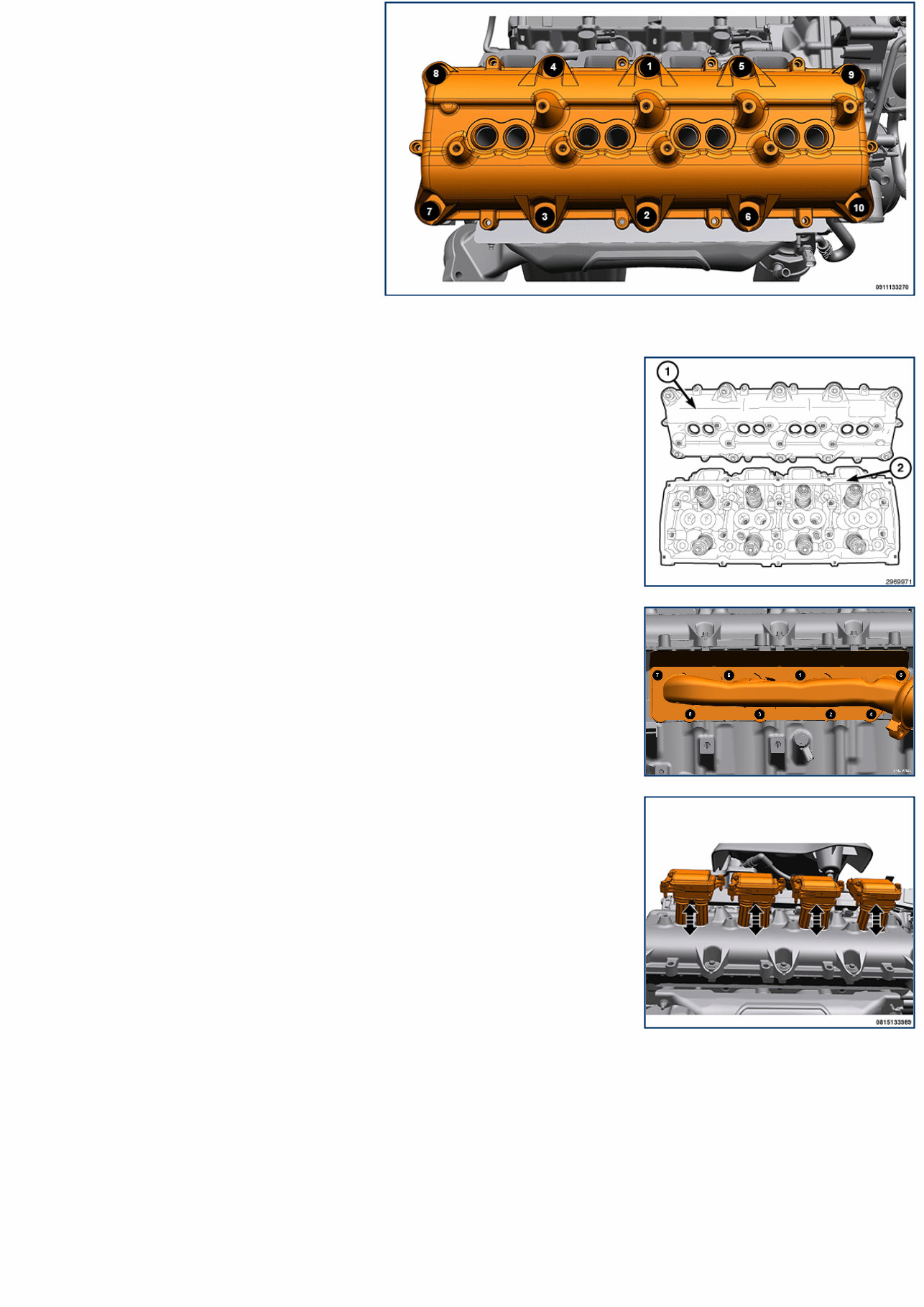
36. Remove the five remaining bolts (1) and the timing cover. 37. Verify that timing cover slide bushing (1) is located in timing cover. 38. Clean the gasket sealing surface. 39. Remove the bolts and all four ignition coils (left side). 40. Using the sequence shown, remove the left cylinder head cover retaining bolts.
Right side shown, left side similar. 41. Remove the left cylinder head cover (1). CAUTION: Do not use harsh cleaners to clean the cylinder head covers. Severe damage to covers may occur. NOTE: The cylinder head cover gasket may be used again, provided no cuts, tears, or deformation have occurred. 42. Clean the sealing surface of the cylinder head (2). 43. Remove the three nuts and the left exhaust manifold head shield. NOTE: All fasteners removed must be installed in the same location they were removed from. 44. Using the sequence shown, remove the bolts and the left exhaust manifold. 45. Clean the gasket sealing surface. 46. Remove the bolts and all four ignition coils (right side). 47. Using the sequence shown, remove the right cylinder head cover retaining bolts.
Get ready to tackle any repair or maintenance task on your 2021 Dodge RAM 1500 DT with confidence! Our comprehensive service and repair manual provide you with all the essential information you need to keep your vehicle running smoothly.
Whether you're a seasoned mechanic or a DIY enthusiast, this manual is your ultimate guide to understanding and maintaining your Dodge RAM 1500 DT. From routine maintenance procedures to complex repairs, we've got you covered.
Key Features:
Easy-to-follow instructions: Step-by-step guidance to help you complete any task with ease.
Comprehensive diagrams: Detailed illustrations and diagrams to aid in understanding every aspect of your vehicle.
Troubleshooting tips: Common problems and solutions to help you diagnose and fix issues quickly.
Vehicle specifications: Detailed information on specifications, including engine, transmission, and more.
Maintenance schedules: Keep your Dodge RAM 1500 DT in top condition with recommended maintenance schedules.
With instant delivery via download link upon purchase, you can access the manual anytime, anywhere. No waiting for shipping – get started on your repairs right away!
Don't let maintenance tasks or repairs intimidate you – empower yourself with the knowledge and guidance provided in our service and repair manual for the 2021 Dodge RAM 1500 DT.