Thank you for buying our digital service manual. This digital manual will help you to maintain and repair your vehicle/outboard/motorcycle/atv. If you have any problems with our service manual please do not hesitate to contact us. For more digital service manuals please click the link below: www.digitalservicemanuals.com
GROUP TAB LOCATOR Introduction 0 Lubrication & Maintenance 2 Suspension 3 Differential & Driveline 5 Brakes 7 Cooling 8A Audio 8B Chime/Buzzer 8E Electronic Control Modules 8F Engine Systems 8G Heated Systems 8H Horn 8I Ignition Control 8J Instrument Cluster 8L Lamps 8M Message Systems 8N Power Systems 8O Restraints 8P Speed Control 8Q Vehicle Theft Security 8R Wipers/Washers 8W Wiring 9 Engine 11 Exhaust System 13 Frame & Bumpers 14 Fuel System 19 Steering 21 Transmission/Transaxle 22 Tires/Wheels 23 Body 24 Heating & Air Conditioning 25 Emissions Control Systems 30 New Vehicle Preparation Component and System Index Service Manual Comment Forms (Rear of Manual)
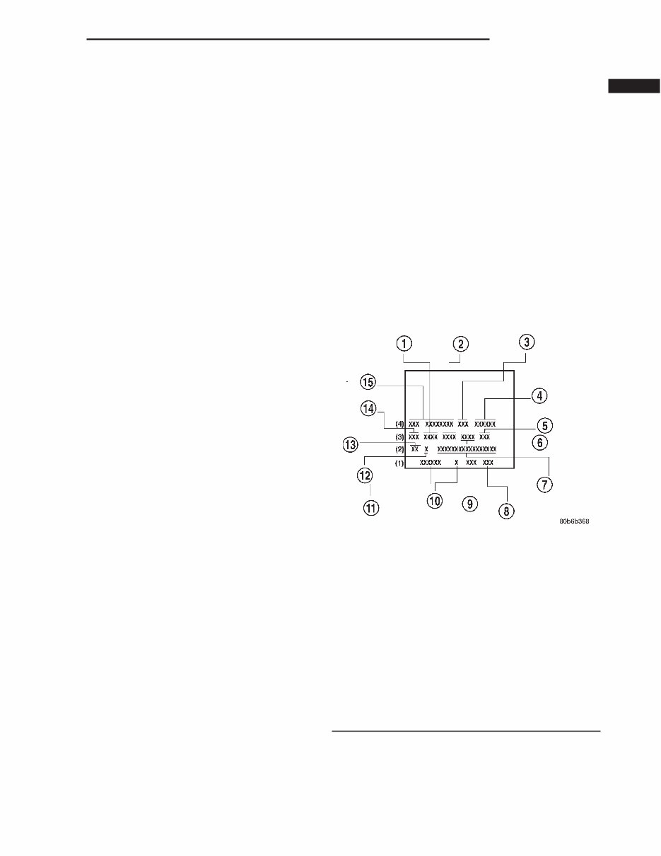
INTRODUCTION TABLE OF CONTENTS page page BODY CODE PLATE DESCRIPTION ............................ 1 FASTENER IDENTIFICATION DESCRIPTION ............................ 3 FASTENER USAGE DESCRIPTION ............................ 6 INTERNATIONAL VEHICLE CONTROL & DISPLAY SYMBOLS DESCRIPTION ............................ 6 METRIC SYSTEM DESCRIPTION ............................ 6 TORQUE REFERENCES DESCRIPTION ............................ 9 VECI LABEL DESCRIPTION ........................... 10 OPERATION............................. 10 VEHICLE IDENTIFICATION NUMBER DESCRIPTION ........................... 10 VEHICLE SAFETY CERTIFICATION LABEL DESCRIPTION ........................... 12 EQUIPMENT IDENTIFICATION PLATE DESCRIPTION ........................... 12 BODY CODE PLATE DESCRIPTION The Body Code Plate (Fig. 1) is located on the floor pan under the passenger seat or attached to the front face of the radiator closure panel. There are seven lines of information on the body code plate. Lines 5, 6, and 7 are not used to define service information. Information reads from left to right, starting with line 4 in the center of the plate to line 1 at the bot- tom of the plate. The last code imprinted on a vehicle code plate will be followed by the imprinted word END. When two vehicle code plates are required, the last available spaces on the first plate will be imprinted with the letters CTD (for continued). When a second vehicle code plate is necessary, the first four spaces on each row will not be used because of the plate overlap. BODY CODE PLATE—LINE 4 DIGITS 1 THROUGH 12 Vehicle Order Number DIGITS 13, 14, AND 15 Transmission Codes • DGP = 4–speed Automatic (47RE) • DGT = 4–speed Automatic (46RE) • DGK = 4–speed Automatic (42RE) • DDP = 5–speed Manual (NVG-4500) • DDX = 5–speed Manual (NVG-4500 Heavy Duty) • DDC = 5–speed Manual (NVG-3500) • DEE = 6–speed Manual (NVG-5600) DIGITS 16, 17, AND 18 Car Line Shell • BR1 = 1500 4 X 2 • BE1 = 1500 4 X 2 • BR6 = 1500 4 X 4 Fig. 1 Body Code Plate 1 - PRIMARY PAINT 2 - SECONDARY PAINT 3 - TRANSMISSION CODE 4 - VEHICLE MODEL NUMBER 5 - ENGINE CODE 6 - INTERIOR TRIM CODE 7 - VEHICLE IDENTIFICATION NUMBER 8 - TAILGATE CODE 9 - CARGO BOX CODE 10 - TAILGATE TRIM CODE 11 - BODY-IN-WHITE SEQUENCE 12 - MARKET CODE 13 - SPECIES CODE 14 - PAINT PROCEDURE 15 - VEHICLE ORDER NUMBER BR/BE INTRODUCTION 1
• BE6 = 1500 4 X 4 • BR2 = 2500 4 X 2 • BE2 = 2500 4 X 2 • BR7 = 2500 4 X 4 • BE7 = 2500 4 X 4 • BR3 = 3500 4 X 2 • BE3 = 3500 4 X 2 • BR8 = 3500 4 X 4 • BE8 = 3500 4 X 4 DIGIT 19 Price Class • L = Ram Truck (All) DIGITS 20 AND 21 Body Type • 31 = Ram Truck Club Cab (138.7 in. Wheel Base) • 32 = Ram Truck Club Cab (154.7 in. Wheel Base) • 33 = Ram Truck Quad Cab (138.7 in. Wheel Base) • 34 = Ram Truck Quad Cab (154.7 in. Wheel Base) • 61 = Ram Truck (118.7 in. Wheel Base) • 62 = Ram Truck (134.7 in. Wheel Base) • 63 = Ram Truck Cab Chassis (138.7 in. Wheel Base) • 64 = Ram Truck Cab Chassis (162.7 in. Wheel Base) BODY CODE PLATE—LINE 3 DIGITS 1,2, AND 3 Paint Procedure • APA = Monotone • AP9 = Special • APB = Two-tone (Waterfall) • APC = Two-tone (Centerband) • APD = Two-tone (Lower break) DIGIT 4 Open Space DIGITS 5 THROUGH 8 Primary Paint Refer to Group 23, Body for color codes. DIGIT 9 Open Space DIGITS 10 THROUGH 13 Secondary Paint DIGIT 14 Open Space DIGITS 15 THROUGH 18 Interior Trim Code DIGIT 19 Open Space DIGITS 20, 21, AND 22 Engine Code • EHC = 3.9 L 6 cyl. MPI Gasoline • ELF = 5.2 L 8 cyl. MPI Gasoline • ELN = 5.2 L 8 cyl. (CNG) • EML = 5.9 L 8 cyl. MPI Gasoline • EMM = 5.9 L 8 cyl. MPI Gasoline (Heavy Duty) • ETC = 5.9 L 6 cyl. Turbo Diesel • EWA = 8.0 L 10 cyl. MPI Gasoline BODY CODE PLATE—LINE 2 DIGIT 1 Open Space DIGITS 2 AND 3 Species Code. (Used for Manufacturing) DIGIT 4 Open Space DIGIT 5 Market Code • B = International • C = Canada • M = Mexico • U = United States DIGIT 6 Open Space DIGITS 7 THROUGH 23 Vehicle Identification Number (VIN) Refer to Vehicle Identification Number (VIN) para- graph for proper breakdown of VIN code. BODY CODE PLATE—LINE 1 DIGITS 1 THROUGH 6 Body-in-white assembly sequence. DIGIT 7 Open Space DIGIT 8 Tailgate trim code. DIGIT 9 Open Space DIGITS 10 THROUGH 12 Cargo box code • XBS = Sweptline DIGIT 13 Open Space 2 INTRODUCTION BR/BE BODY CODE PLATE (Continued)
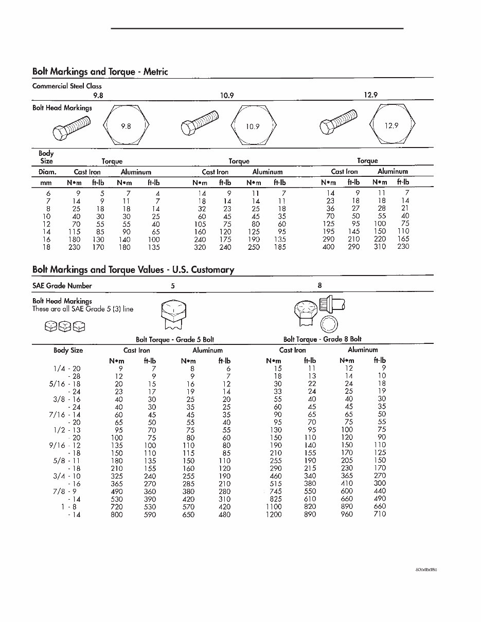
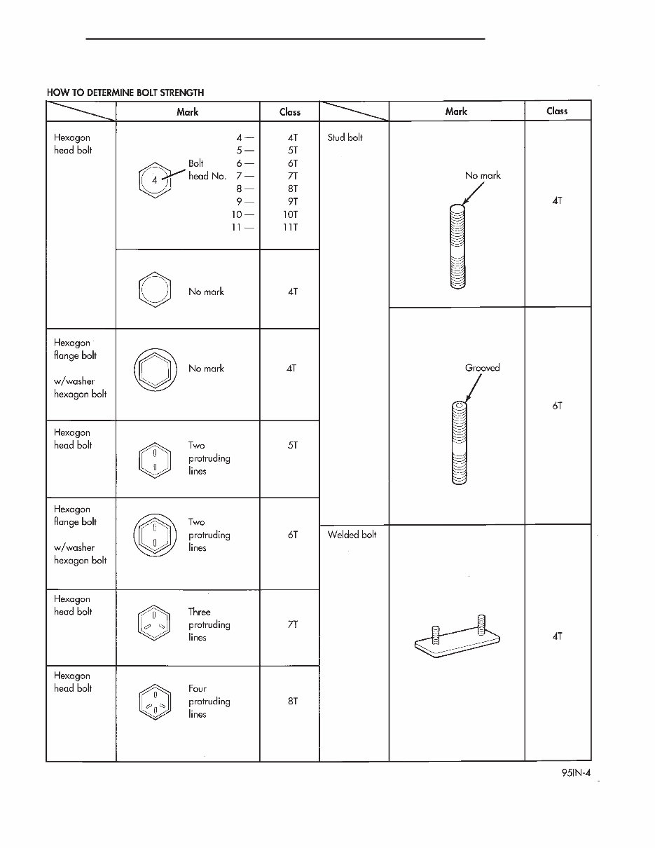
DIGITS 14 THROUGH 16 Tailgate code • MWD = Plain Tailgate • MPB = Tailgate Applique (Black) FASTENER IDENTIFICATION DESCRIPTION The SAE bolt strength grades range from grade 2 to grade 8. The higher the grade number, the greater the bolt strength. Identification is determined by the line marks on the top of each bolt head. The actual bolt strength grade corresponds to the number of line marks plus 2. The most commonly used metric bolt strength classes are 9.8 and 10.9. The metric strength class identification number is imprinted on the head of the bolt. The higher the class number, the greater the bolt strength. Some metric nuts are imprinted with a single-digit strength class on the nut face. Refer to the Fastener Identification and Fastener Strength Charts. BR/BE INTRODUCTION 3 BODY CODE PLATE (Continued)
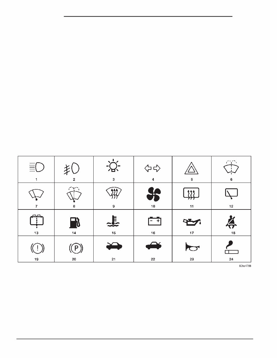
FASTENER USAGE DESCRIPTION - FASTENER USAGE WARNING: USE OF AN INCORRECT FASTENER MAY RESULT IN COMPONENT DAMAGE OR PER- SONAL INJURY. Figure art, specifications and torque references in this Service Manual are identified in metric and SAE format. During any maintenance or repair procedures, it is important to salvage all fasteners (nuts, bolts, etc.) for reassembly. If the fastener is not salvageable, a fastener of equivalent specification must be used. DESCRIPTION - THREADED HOLE REPAIR Most stripped threaded holes can be repaired using a Helicoilt. Follow the manufactures recommenda- tions for application and repair procedures. INTERNATIONAL VEHICLE CONTROL & DISPLAY SYMBOLS DESCRIPTION - INTERNATIONAL SYMBOLS The graphic symbols illustrated in the following International Control and Display Symbols Chart are used to identify various instrument controls. The symbols correspond to the controls and displays that are located on the instrument panel. METRIC SYSTEM DESCRIPTION - METRIC SYSTEM The metric system is based on quantities of one, ten, one hundred, one thousand and one million . The following chart will assist in converting metric units to equivalent English and SAE units, or vise versa. International Symbols 1 High Beam 13 Rear Window Washer 2 Fog Lamps 14 Fuel 3 Headlamp, Parking Lamps, Panel Lamps 15 Engine Coolant Temperature 4 Turn Warning 16 Battery Charging Condition 5 Hazard Warning 17 Engine Oil 6 Windshield Washer 18 Seat Belt 7 Windshield Wiper 19 Brake Failure 8 Windshield Wiper and Washer 20 Parking Brake 9 Windscreen Demisting and Defrosting 21 Front Hood 10 Ventilating Fan 22 Rear hood (Decklid) 11 Rear Window Defogger 23 Horn 12 Rear Window Wiper 24 Lighter 6 INTRODUCTION BR/BE
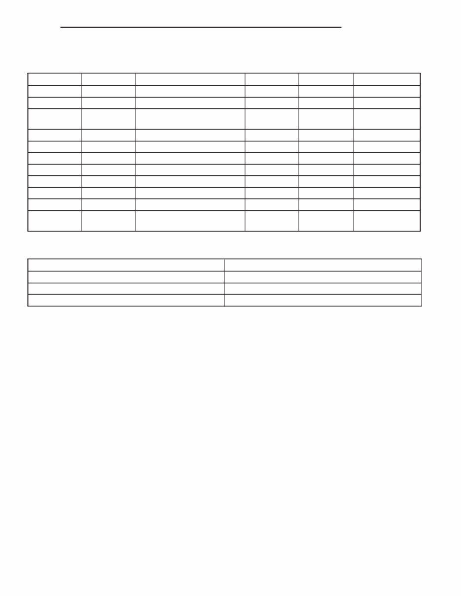
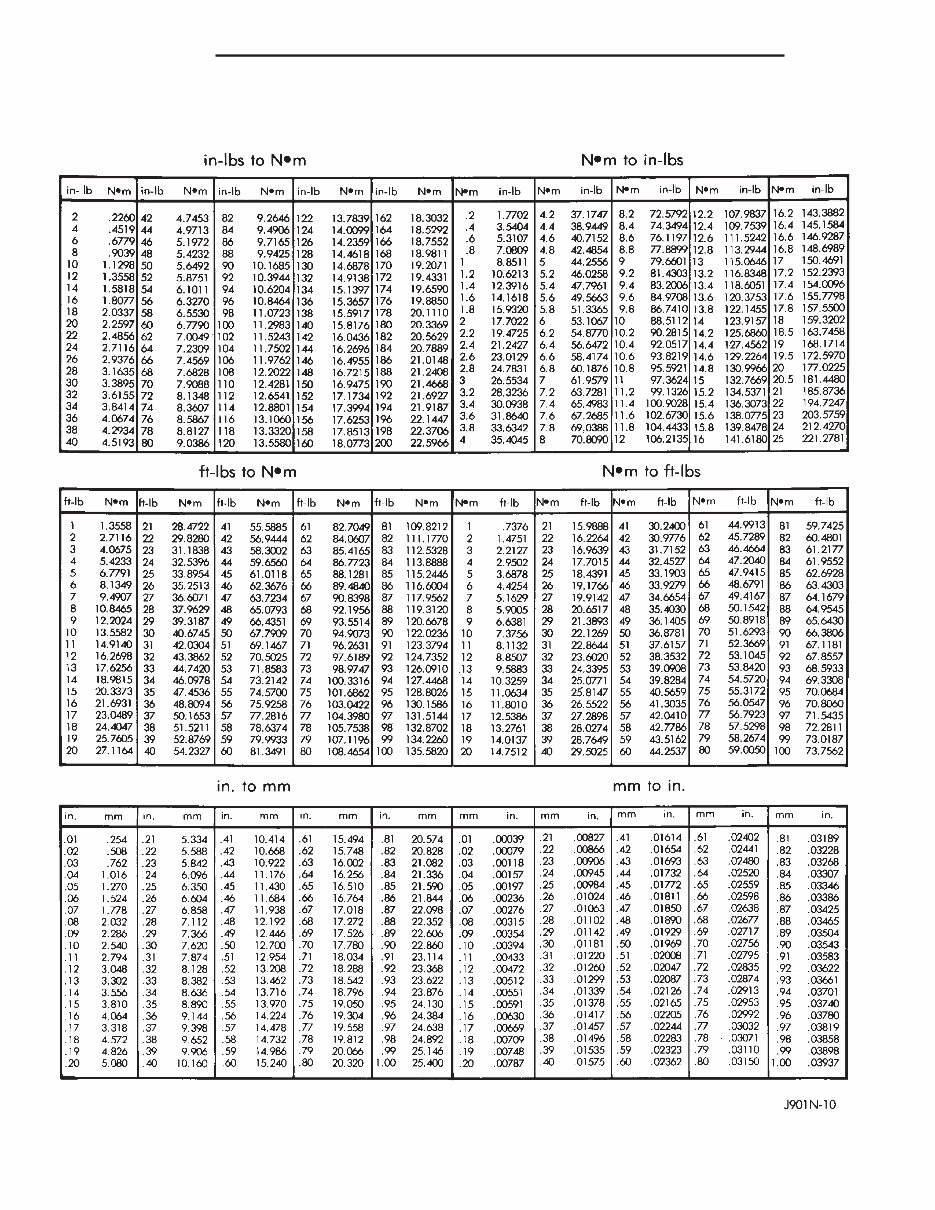
CONVERSION FORMULAS AND EQUIVALENT VALUES MULTIPLY BY TO GET MULTIPLY BY TO GET in-lbs x 0.11298 = Newton Meters (N·m) N·m x 8.851 = in-lbs ft-lbs x 1.3558 = Newton Meters (N·m) N·m x 0.7376 = ft-lbs Inches Hg (60° F) x 3.377 = Kilopascals (kPa) kPa x 0.2961 = Inches Hg psi x 6.895 = Kilopascals (kPa) kPa x 0.145 = psi Inches x 25.4 = Millimeters (mm) mm x 0.03937 = Inches Feet x 0.3048 = Meters (M) M x 3.281 = Feet Yards x 0.9144 = Meters M x 1.0936 = Yards mph x 1.6093 = Kilometers/Hr. (Km/h) Km/h x 0.6214 = mph Feet/Sec x 0.3048 = Meters/Sec (M/S) M/S x 3.281 = Feet/Sec mph x 0.4470 = Meters/Sec (M/S) M/S x 2.237 = mph Kilometers/ Hr. (Km/h) x 0.27778 = Meters/Sec (M/S) M/S x 3.600 Kilometers/Hr. (Km/h) COMMON METRIC EQUIVALENTS 1 inch = 25 Millimeters 1 Cubic Inch = 16 Cubic Centimeters 1 Foot = 0.3 Meter 1 Cubic Foot = 0.03 Cubic Meter 1 Yard = 0.9 Meter 1 Cubic Yard = 0.8 Cubic Meter 1 Mile = 1.6 Kilometers Refer to the Metric Conversion Chart to convert torque values listed in metric Newton- meters (N·m). Also, use the chart to convert between millimeters (mm) and inches (in.) BR/BE INTRODUCTION 7 METRIC SYSTEM (Continued)
Metric Conversion Chart 8 INTRODUCTION BR/BE METRIC SYSTEM (Continued)
This automotive service repair manual is designed for Windows XP, Vista, Windows 7, and Mac, providing all the necessary instructions for comprehensive vehicle repair from bumper to bumper. It is the same manual utilized by technicians and mechanics for vehicle diagnosis and repair, offering the most complete and accurate information available. The clear and concise text, along with detailed illustrations, enables individuals with basic mechanical knowledge to safely and easily service and repair their vehicles. The manual includes comprehensive diagrams, in-depth illustrations, and all the manufacturer's specifications and technical information required.