FOREWORD - The information contained in this service manual has been prepared for the professional automotive tech- nician involved in daily repair operations. This manual does not cover theory of operation, which is addressed in service training material. Information describing the operation and use of standard and optional equipment is included in the Owner's Manual provided with the vehicle. Information in this manual is divided into groups. These groups contain general information, diagnosis, testing, adjustments, removal, installation, disassembly, and assembly procedures for the components, lb as- sist in locating a group title page, use the Group Tab Locator on the following page. The solid bar after the group title is aligned to a solid tab on the first page of each group. The first page of the group has a contents section that lists major topics within the group. If you are not sure which Group contains the information you need, look up the Component/System in the alphabetical index located in the rear of this manual. A Service Manual Comment form is included at the rear of this manual. Use the form to provide Chrysler Corporation with your comments and suggestions. Tightening torques are provided as a specific value throughout this manual. This value represents the midpoint of the acceptable engineering torque range for a given fastener application. These torque values are intended for use in service assembly and installation procedures using the correct OEM fasteners. When re- placing fasteners, always use the same type (part number) fastener as removed. Chrysler Corporation reserves the right to change testing procedures, specifications, diagnosis, repair methods, or vehicle wiring at any time without prior notice or incurring obligation. NOTE: The acronyms, terminology and nomenclature used to identify emissions related components in this manual may have changed from prior publications. These new terms are in compliance with S.A.E. recommended practice J1930.
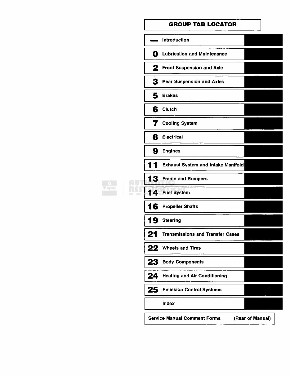
GROUP TAB LOCATOR Introduction 0 Lubrication and Maintenance 2 Front Suspension and Axle 3 Rear Suspension and Axles 5 Brakes j- j v # :: 3 6 Clutch HHHHHHjj 7 Cooling System 8 Electrical v ^i 9 Engines 11 Exhaust System and Intake Manifold 13 Frame and Bumpers 14 Fuel System 16 Propeller Shafts 19 Steering , v-.--.'\. 21 Transmissions and Transfer Cases 22 Wheels and Tires 23 Body Components 24 Heating and Air Conditioning . , f..- '• 7;.^' 25 Emission Control Systems Index Service Manual Comment Forms (Rear of Manual)
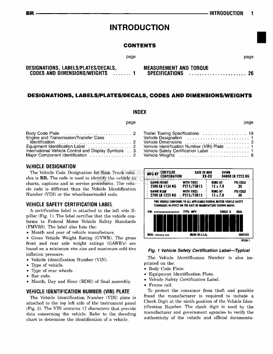
BR INTRODUCTION 1 INTRODUCTION CONTENTS page page DESIiNATIONS, LA1ELS/PLATE8/DECALS, l E I S U i E i E N T AND TOFtQUE COOES ANi DilENSIONS/WEIiHTS 1 SPECIFICATIONS 21 DESIGNATIONS, LABELS/PLATES/DECALS, CODES AND DIMENSIONS/WEIGHTS INDEX page Body Code Plate 2 Engine and Transmission/Transfer Case Identification 2 Equipment Identification Label 2 International Vehicle Control and Display Symbols . . 3 Major Component Identification 2 VEHICLE DESIGNATION The Vehicle Code Designation for Ram Truck vehi- cles is BR. The code is used to identify the vehicle in charts, captions and in service procedures. The vehi- cle code is different than the Vehicle Identification Number (V1N) or the wheelbase/model code. VEHICLE SAFETY CERTIFICATION LABEL A certification label is attached to the left side B- pillar (Fig. 1). The label certifies that the vehicle con- forms to Federal Motor Vehicle Safety Standards (FMVSS). The label also lists the: • Month and year of vehicle manufacture. • Gross Vehicle Weight Rating (GVWR). The gross front and rear axle weight ratings (GAWR's) are based on a minimum rim size and maximum cold tire inflation pressure. • Vehicle Identification Number (VIN). • Type of vehicle. ® Type of rear wheels . • Bar code. • Month, Day and Hour (SlDH) of final assembly. VEHICLE IDENTIFICATION NUMBER (VIN) PLATE The Vehicle Identification Number (VIN) plate is attached to the top left side of the instrument panel (Fig. 2). The VIN contains 17 characters that provide data concerning the vehicle. Refer to the decoding chart to determine the identification of a vehicle. page Trailer Towing Specifications 19 Vehicle Designation . 1 Vehicle Dimensions . 3 Vehicle Identification Number (VIN) Plate 1 Vehicle Safety Certification Label ............... 1 Vehicle Weights 8 m r v B I CORPORATION XX-XX 04800 LB 2223 KG ' GAWR FRONT ; WITH TIRES > RIMS AT PSI COLD > | 2500 LB 1134 KG j P215/75R15 j 15x 7.0 30 | ; GAWR REAR ' WITH TIRES \ RIMS AT PSI COLD ! j 2700 LB 1225 KG j P215/7SR15 j 15x 7.0 30 j TNIS VEHKLE CONFORMS TO ALL APPLKAILE FEDERAL MOTOR VEHKLE SAFETY STANDARDS IN EFFECT ON THE DATE OF MANUFACTURE SHOWN ABOVE. VIN: xxxxxxxxxxxxxxxxx TYPE: MPV SINGLE X DUAL MDH: xxxxxx xxx MADE IN U.SJL. 4340503 J95IN-1 Fig. 1 Vehicle Safety Certification Label—Typical The Vehicle Identification Number is also im- printed on the: • Body Code Plate. ' Equipment Identification Plate. • Vehicle Safety Certification Label. • Frame rail. To protect the consumer from theft and possible fraud the manufacturer is required to include a Check Digit at the ninth position of the Vehicle Iden- tification Number. The check digit is used by the manufacturer and government agencies to verify the authenticity of the vehicle and official documenta-
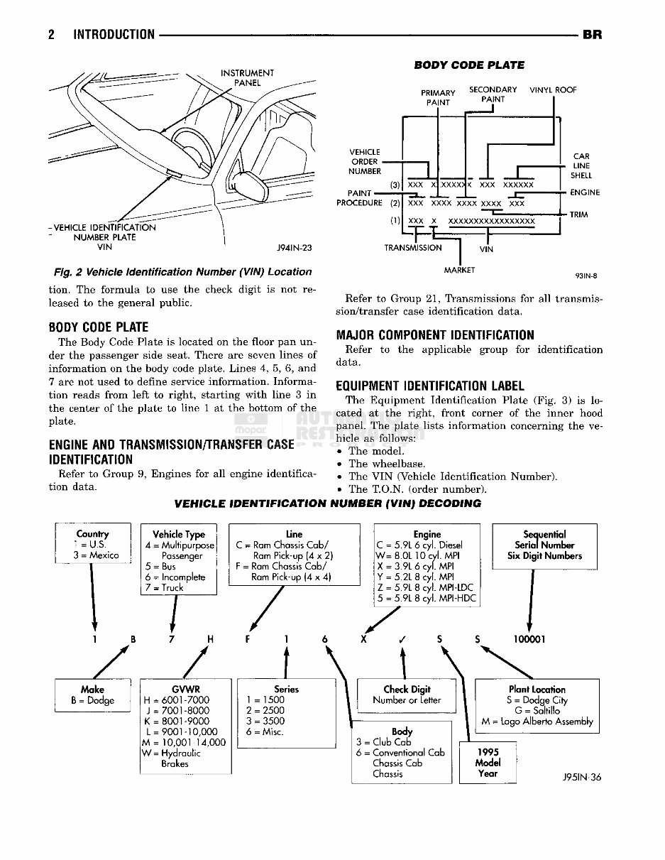
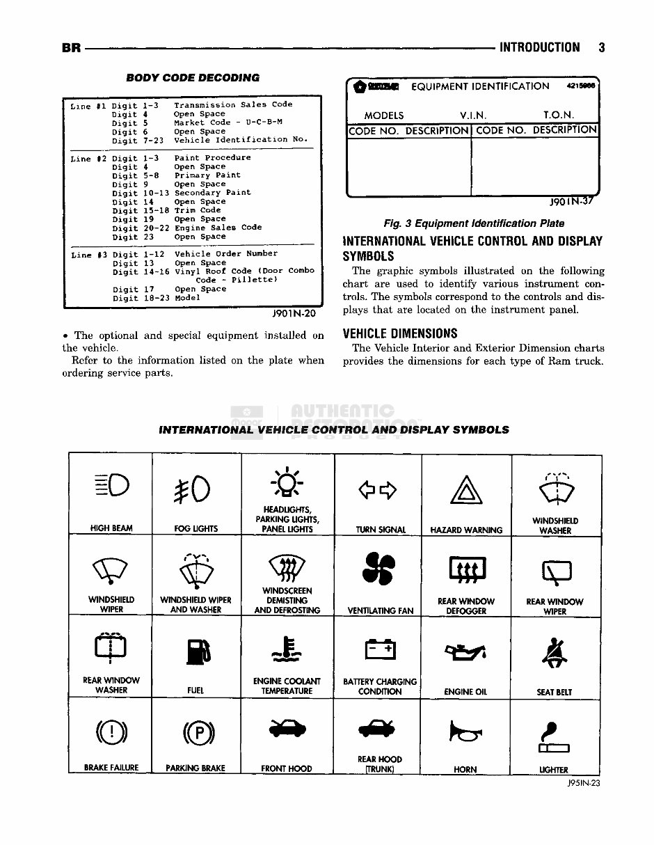
2 INTRODUCTION BR NSTRUMENT -VEHICLE IDENTIFICATION NUMBER PLATE VIN J94SN -23 BODY CODE PLATE PRIMARY SECONDARY VINYL ROOF PAINT PAINT VEHICLE ORDER - NUMBER PAINT - (3) PROCEDURE (2) (1) XXX X _ ± _r XXXX> K XXX xxxxxx XXX xxxx xxxx xxxx XXX XXX X XXXXXXXXXXXXXXXXX Fig. 2 Vehicle Identification Number (VIN) Location tion. The formula to use the check digit is not re- leased to the general public. BODY CODE PLATE The Body Code Plate is located on the floor pan un- der the passenger side seat. There are seven lines of information on the body code plate. Lines 4, 5, 6, and 7 are not used to define service information. Informa- tion reads from left to right, starting with line 3 in the center of the plate to line 1 at the bottom of the plate. ENGINE AND TRANSMISSION/TRANSFER CASE IDENTIFICATION Refer to Group 9, Engines for all engine identifica- tion data. VEHICLE IDENTIFICATION ON j CAR LINE SHELL ENGINE •TRIM TRANSMISSION | VIN AAARKET 93IN-8 Refer to Group 21, Transmissions for all transmis- sion/transfer case identification data. 1AJ0R COiPONENT IDENTIFICATION Refer to the applicable group for identification data. E0U1P1ENT IDENTIFICATION LABEL The Equipment Identification Plate (Fig. 3) is lo- cated at the right, front corner of the inner hood panel. The plate lists information concerning the ve- hicle as follows: • The model. • The wheelbase. • The VIN (Vehicle Identification Number). • The T.O.N, (order number). NUMBER (VIN) DECODING 1 B z. Moke B = Dodge Vehicle Type 4 = Multipurpose Passenger 5 = Bus 6 = Incomplete 7 = Truck 7 n z Line C = Ram Chassis Cab/ Ram Pick-up (4 x 2) F = Ram Chassis Cab/ Ram Pick-up (4 x 4) GVWR H = 6001 -7000 J - 7001-8000 K = 8001-9000 L = 9001-10,000 M = 10,001-14,000 W = Hydraulic Brakes Engine C = 5.9L 6 cyl. Diesel W= 8.0L 10 cyl. MPI X = 3.9L 6 cyl. MPI Y = 5.2L 8 cyl. MPI Z = 5.9L 8 cyl. MPI-LDC 5 = 5.9L 8 cyl. MPI-HDC Check Digit Number or Letter Body 3 = Club Cab 6 = Conventional Cab Chassis Cab Chassis Sequential Serial Number Six Digit Numbers 100001 Plant Location S = Dodge City G = Saltillo Lago Alberto Assembly J95IN-36
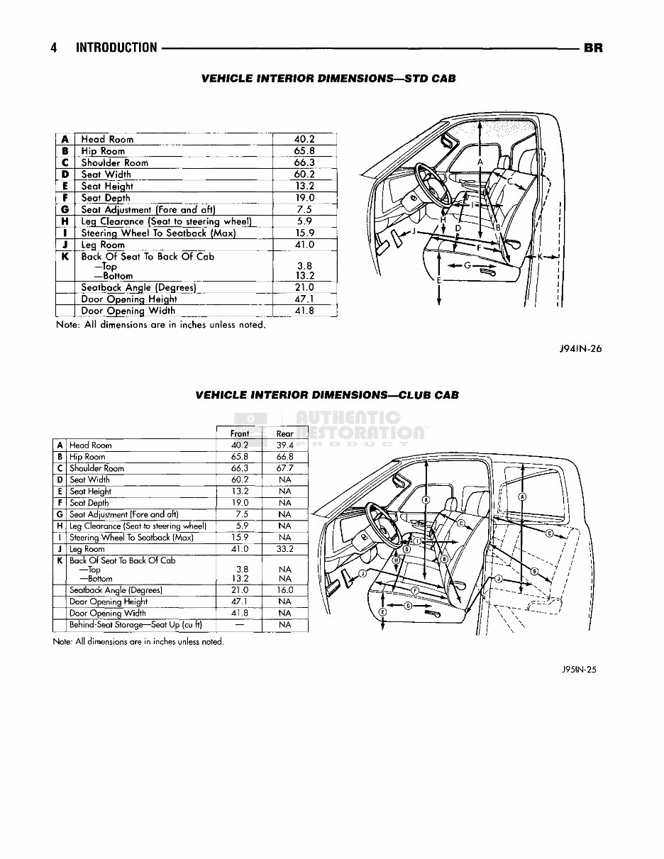
4 INTRODUCTION BR VEHICLE INTERIOR DIMENSIONS—STD CAB A Head Room 40.2 B Hip Room 65.8 C Shoulder Room 66.3 D Seat Width 60.2 E Seat Height 13.2 F Seat Depth 19.0 c§ Seat Adjustment (Fore and aft) 7.5 H Leg Clearance (Seat to steering wheel) 5.9 I Steering Wheel To Seatback (Max) 15.9 J Leg Room 41.0 §c Back Of Seat To Back Of Cab —Top —Bottom 3.8 13.2 Seatback Angle (Degrees) 21.0 Door Opening Height 47.1 Door Opening Width 41.8 Note: All dimensions are in inches unless noted. J94IN-26 VEHICLE INTERIOR DIMENSIONS—CLUB CAB Front Rear A Head Room 40.2 39.4 B Hip Room 65.8 66 8 C Shoulder Room 66.3 67.7 D Seat Width 60.2 NA E Seat Height 13.2 NA F Seat Depth 19.0 NA G Seat Adjustment (Fore and aft) 7.5 NA H Leg Clearance (Seat to steering wheel) 5.9 NA 1 Steering Wheel To Seatback (Max) 15.9 NA J Leg Room 41.0 33.2 K Back Of Seat To Back Of Cab —Top —Bottom 3.8 13.2 NA NA Seatback Angle (Degrees) 21.0 16.0 Door Opening Height 47.1 NA Door Opening Width 41.8 NA Behind-Seat Storage—Seat Up (cu ft) — NA Note: All dimensions are in inches unless noted. J95IN-25
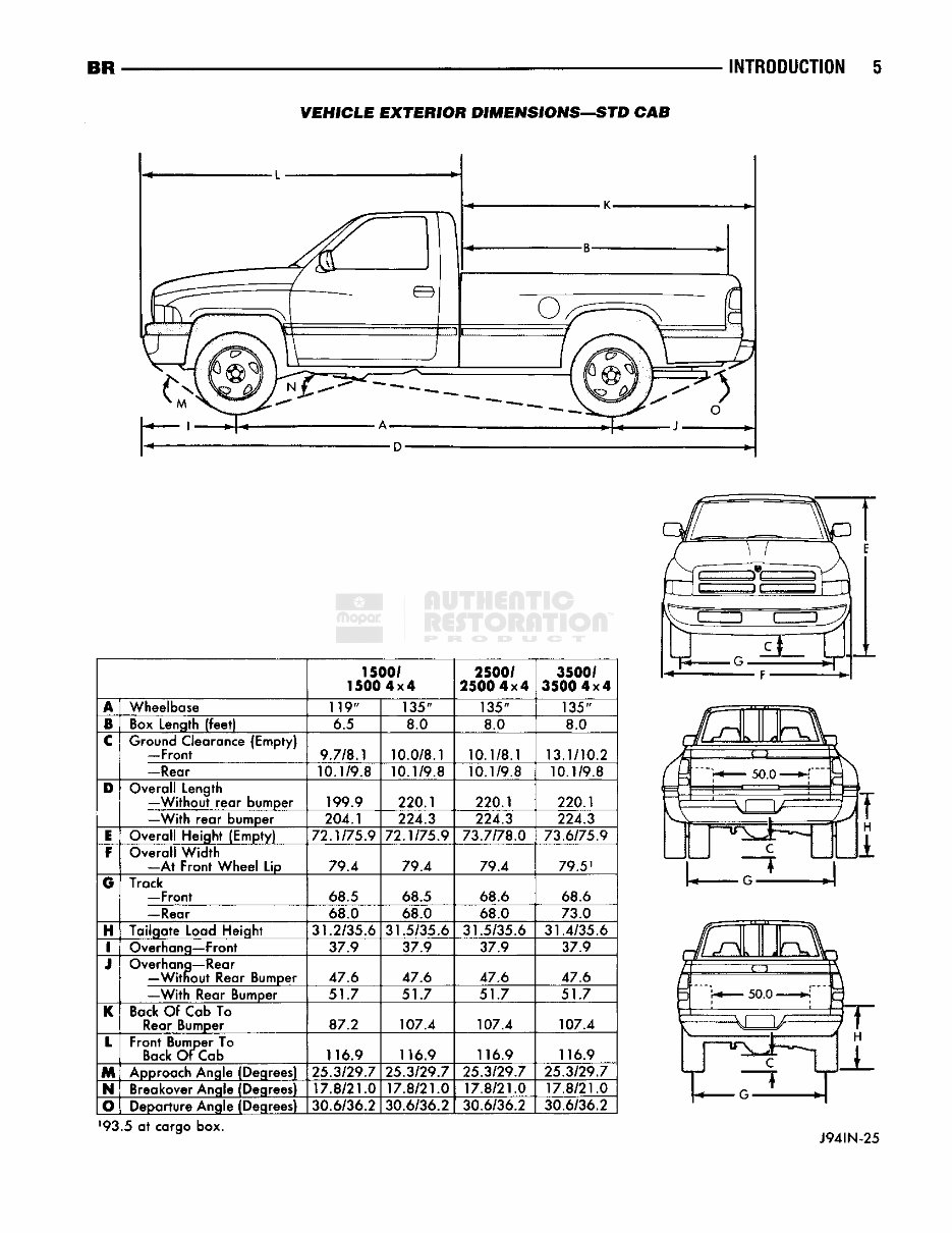
BR INTRODUCTION 5 VEHICLE EXTERIOR DIMENSIONS—STD CAB 1500/ 1500 4x4 2500/ 2500 4x4 3500/ 3500 4x4 A Wheelbase 119" 135" 135" 135" 1 Box Length (feet) 6.5 8.0 8.0 8.0 C Ground Clearance {Empty) —Front 9.7/8.1 10.0/8.1 10.1/8.1 13.1/10.2 —Rear 10.1/9.8 10.1/9.8 10.1/9.8 10.1/9.8 D Overall Length -—Without rear bumper 199.9 220.1 220.1 220.1 —With rear bumper 204.1 224.3 224.3 224.3 1 Overall Height (Empty) 72.1/75.9 72.1/75.9 73.7/78.0 73.6/75.9 F Overall Width —At Front Wheel Lip 79.4 79.4 79.4 79.5 1 G Track ' —Front 68.5 68.5 68.6 68.6 —Rear 68.0 68.0 68.0 73.0 H Tailgate Load Height 31.2/35.6 31.5/35.6 31.5/35.6 31.4/35.6 1 Overhang—Front 37.9 37.9 37.9 37 Q J Overhang—Rear —Without Rear lumper 47.6 47.6 47.6 47.6 —With Rear lumper 51.7 51.7 51.7 51.7 K Back Of Cab To Rear Bumper 87.2 107.4 107.4 107.4 L Front Bumper To Back Of Cab 116.9 116.9 116.9 116.9 M Approach Angle (Degrees) 25.3/29.7 25.3/29.7 25.3/29.7 25.3/29.7 M Breakover Angle (Degrees) 17.8/21.0 17.8/21.0 17.8/21.0 17.8/21.0 o Departure Angle (Degrees) 30.6/36.2 30.6/36.2 30,6/36.2 30.6/36.2 5u_ KV 50.0 C } 93.5 at cargo box. J94IN-25
You're Reading a Preview
What's Included?
Lifetime Access
Fast Download Speeds
Online & Offline Access
Access PDF Contents & Bookmarks
Full Search Facility
Print one or all pages of your manual
$40.99
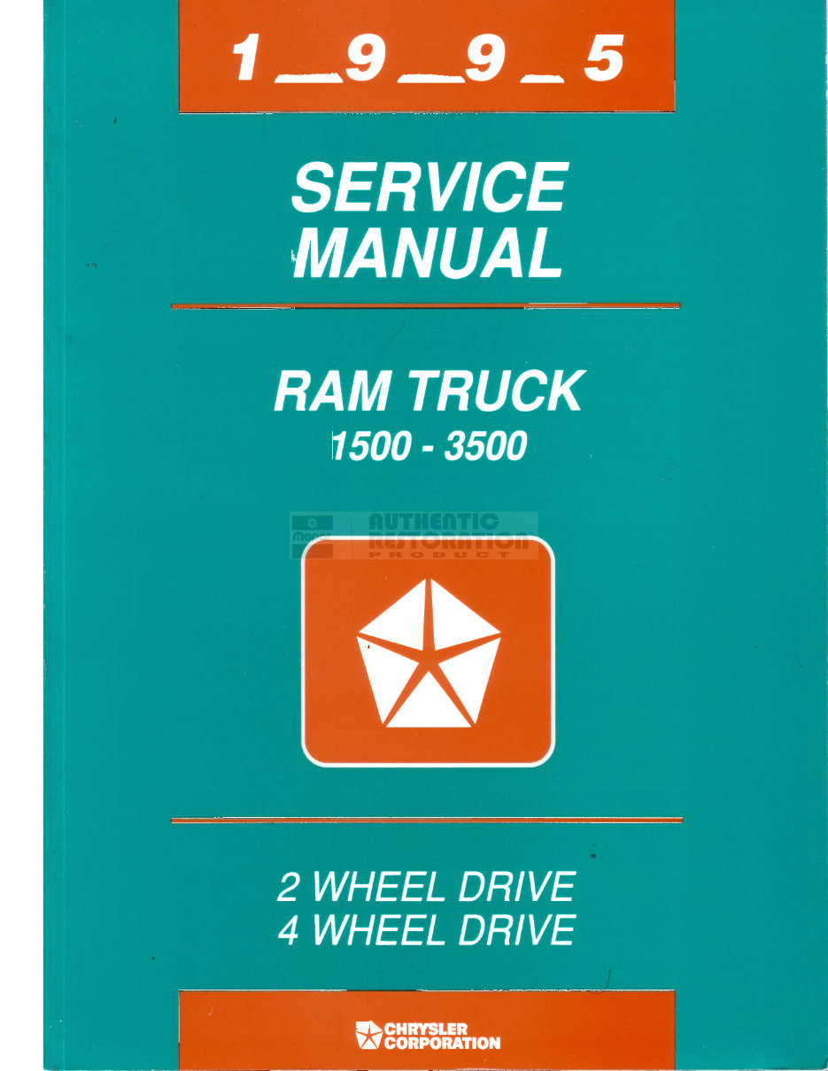
1995 Dodge Ram 1500/2500/3500 Series Service & Repair Manual
1995 Dodge Ram 1500/2500/3500 Series Service & Repair Manual
Engines covered:
3.9 L Magnum V6
5.2 L Magnum V8
5.9 L Cummins turbo-diesel I6
5.9 L Magnum V8
8.0 L Magnum V10
Transmissions covered:
42RH-RE 4-speed automatic
46RH-RE 4-speed automatic
47RH-RE 4-speed automatic
NV3500 5-speed manual
NV4500 5-speed manual
For both professional mechanics and DIY enthusiasts, this repair manual provides every troubleshooting and replacement procedure recommended by the manufacturer. It includes step-by-step instructions, clear images, and exploded-view illustrations.
Regular maintenance is essential for the durability of your truck. Over time, some parts will wear out and require replacement. This manual offers the manufacturer's recommended troubleshooting charts and replacement procedures, enabling you to save on repairs, increase your vehicle’s reliability, and minimize visits to the repair shop.
Featuring step-by-step instructions, exploded-view illustrations, and clear images, the manual eliminates the need to search through numerous pages for specific information. It is easily accessible, searchable, and portable, making it more convenient than a traditional bound manual.
Additionally, it is printable and compatible with various electronic devices, including PC & Mac computers, Android and Apple smartphones & tablets, etc. The only requirement is Adobe Reader, which is available for free.
Reviews
Q&A
Recently Viewed
5,521,897Happy Clients
2,594,462eManuals
1,120,453Trusted Sellers
15Years in Business
Price:
Actual Price:
1995 Dodge Ram 1500/2500/3500 Series Service & Repair Manual