

Dodge Nitro 2007 Service Manual
What's Included?
Fast Download Speeds
Online & Offline Access
Access PDF Contents & Bookmarks
Full Search Facility
Print one or all pages of your manual

2007-2008 Dodge Nitro
ENGINE
3.7L - Service Information - Nitro
DESCRIPTION
3.7L ENGINE DESCRIPTION
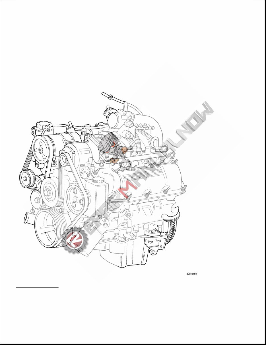
Fig. 1: 3.7L Engine
Courtesy of CHRYSLER LLC
The 3.7 liter (226 CID) six-cylinder engine is an 90° single overhead camshaft engine. The cast iron cylinder
block is made up of two different components; the first component is the cylinder bore and upper block, the
second component is the bedplate that comprises the lower portion of the cylinder block and houses the lower
half of the crankshaft main bearings. The cylinders are numbered from front to rear with the left bank being
numbered 1,3, and 5 and the right bank being numbered 2,4, and 6. The firing order is 1-6-5-4-3-2. The engine
serial number is located at the right front side of the engine block. See Fig. 1 .
DIAGNOSIS AND TESTING
CYLINDER COMBUSTION PRESSURE LEAKAGE
The combustion pressure leakage test provides an accurate means for determining engine condition.
Combustion pressure leakage testing will detect:
Exhaust and intake valve leaks (improper seating).
Leaks between adjacent cylinders or into water jacket.
Any causes for combustion/compression pressure loss.
1. Check the coolant level and fill as required. DO NOT install the radiator cap.
2. Start and operate the engine until it attains normal operating temperature, then turn the engine OFF.
3. Remove the spark plugs.
4. Remove the oil filler cap.
5. Remove the air cleaner.
6. Calibrate the tester according to the manufacturer's instructions. The shop air source for testing should
maintain 483 kPa (70 psi) minimum, 1,379 kPa (200 psi) maximum and 552 kPa (80 psi) recommended.
7. Perform the test procedures on each cylinder according to the tester manufacturer's instructions. Set
piston of cylinder to be tested at TDC compression. While testing, listen for pressurized air escaping
through the throttle body, tailpipe and oil filler cap opening. Check for bubbles in the radiator coolant.
All gauge pressure indications should be equal, with no more than 25% leakage.
FOR EXAMPLE: At 552 kPa (80 psi) input pressure, a minimum of 414 kPa (60 psi) should be maintained in
the cylinder.
Refer to CYLINDER COMBUSTION PRESSURE LEAKAGE DIAGNOSIS CHART .
CYLINDER COMBUSTION PRESSURE LEAKAGE DIAGNOSIS CHART
CONDITION POSSIBLE CAUSE CORRECTION
AIR ESCAPES THROUGH
THROTTLE BODY
Intake valve bent, burnt, or not
seated properly
Inspect valve and valve seat.
Reface or replace, as necessary.
Inspect valve springs. Replace as
necessary.
AIR ESCAPES THROUGH
TAILPIPE
Exhaust valve bent, burnt, or not
seated properly
Inspect valve and valve seat.
Reface or replace, as necessary.
Inspect valve springs. Replace as
necessary.
CYLINDER COMPRESSION PRESSURE
The results of a cylinder compression pressure test can be utilized to diagnose several engine malfunctions.
Ensure the battery is completely charged and the engine starter motor is in good operating condition. Otherwise
the indicated compression pressures may not be valid for diagnosis purposes.
1. Clean the spark plug recesses with compressed air.
2. Remove the spark plugs.
3. Secure the throttle in the wide-open position.
4. Disable the fuel system (Refer to FUEL DELIVERY - GAS ).
5. Remove the ASD relay. Refer to REMOVAL .
6. Insert a compression pressure gauge and rotate the engine with the engine starter motor for three
revolutions.
7. Record the compression pressure on the 3rd revolution. Continue the test for the remaining cylinders.
8. See SPECIFICATIONS for the correct engine compression pressures.
ENGINE DIAGNOSIS - INTRODUCTION
Engine diagnosis is helpful in determining the causes of malfunctions not detected and remedied by routine
maintenance.
These malfunctions may be classified as either performance (e.g, engine idles rough and stalls) or mechanical
(e.g, a strange noise).
See ENGINE PERFORMANCE DIAGNOSTIC TABLE and ENGINE MECHANICAL DIAGNOSTIC
TABLE for possible causes and corrections of malfunctions. Refer to DIAGNOSIS AND TESTING for fuel
system diagnosis.
Additional tests and diagnostic procedures may be necessary for specific engine malfunctions that can not be
isolated with the Service Diagnosis charts. Information concerning additional tests and diagnosis is provided
within the following diagnosis:
Cylinder Compression Pressure Test. See CYLINDER COMPRESSION PRESSURE .
AIR ESCAPES THROUGH
RADIATOR
Head gasket leaking or cracked
cylinder head or block
Remove cylinder head and
inspect. Replace defective part
MORE THAN 50% LEAKAGE
FROM ADJACENT
CYLINDERS
Head gasket leaking or crack in
cylinder head or block between
adjacent cylinders
Remove cylinder head and
inspect. Replace gasket, head, or
block as necessary
MORE THAN 25% LEAKAGE
AND AIR ESCAPES THROUGH
OIL FILLER CAP OPENING
ONLY
Stuck or broken piston rings;
cracked piston; worn rings and/or
cylinder wall
Inspect for broken rings or piston.
Measure ring gap and cylinder
diameter, taper and out-of-round.
Replace defective part as
necessary
Cylinder Combustion Pressure Leakage Test. See CYLINDER COMBUSTION PRESSURE
LEAKAGE .
Engine Cylinder Head Gasket Failure Diagnosis. See CYLINDER HEAD GASKET (Left) or
CYLINDER HEAD GASKET (Right).
Intake Manifold Leakage Diagnosis. See DIAGNOSIS AND TESTING .
ENGINE LUBRICATION DIAGNOSTIC TABLE
CONDITION POSSIBLE CAUSES CORRECTION
OIL LEAKS 1. Gaskets and O-Rings. -
(a) Misaligned or damaged. (a) Replace as necessary.
(b) Loose fasteners, broken or
porous metal parts.
(b) Tighten fasteners, Repair or
replace metal parts.
2. Crankshaft rear seal 2. Replace as necessary. See
REMOVAL .
3. Crankshaft seal flange.
Scratched, nicked or grooved.
3. Polish or replace crankshaft.
4. Oil pan flange cracked. 4. Replace oil pan. See
REMOVAL .
5. Timing chain cover seal
damaged.
5. Reseal timing cover.
6. Scratched or damaged vibration
damper hub.
6. Polish or replace damper.
OIL PRESSURE DROP 1. Low oil level. 1. Check and correct oil level.
2. Faulty oil pressure sending unit. 2. Replace sending unit. See
REMOVAL .
3. Low oil pressure. 3. Check oil pump and bearing
clearance.
4. Clogged oil filter. 4. Replace oil filter. See
REMOVAL .
5. Worn oil pump. 5. Replace oil pump. See
REMOVAL .
6. Thin or diluted oil. 6. Change oil and filter.
7. Excessive bearing clearance. 7. Replace as necessary.
8. Oil pump relief valve stuck. 8. Replace oil pump. See
REMOVAL .
9. Oil pick up tube loose, damaged
or clogged.
9. Replace as necessary.
OIL PUMPING AT RINGS;
SPARK PLUGS FOULING
1. Worn or damaged rings. 1. Hone cylinder bores and replace
rings.
2. Carbon in oil ring slots. 2. Replace rings. See
STANDARD PROCEDURE .
3. Incorrect ring size installed. 3. Replace rings. See
STANDARD PROCEDURE .
ENGINE MECHANICAL DIAGNOSTIC TABLE
ENGINE PERFORMANCE DIAGNOSTIC TABLE
4. Worn valve guides. 4. Ream guides and replace
valves. See STANDARD
PROCEDURE .
5. Leaking valve guide seals. 5. Replace valve guide seals.
CONDITION POSSIBLE CAUSES CORRECTIONS
NOISY VALVES 1. High or low oil level in
crankcase.
1. Refer to SPECIFICATIONS .
2. Thin or diluted oil. 2. Change oil and filter.
3. Low oil pressure. 3. Check oil pump, if OK, check rod
and main bearings for excessive
wear.
4. Dirt in lash adjusters. 4. Clean or replace as necessary.
5. Worn rocker arms. 5. Replace as necessary.
6. Worn valve guides. 6. See STANDARD
PROCEDURE .
7. Excessive runout of valve
seats.
7. Service valves and valve seats.
See STANDARD PROCEDURE .
ENGINE VIBRATION 1. Counter Balance Shaft not
timed properly
1. Refer to VALVE TIMING .
CONNECTING ROD NOISE 1. Insufficient oil supply. 1. Refer to SPECIFICATIONS .
2. Low oil pressure. 2. Check oil pump, if OK, check rod
and main bearings for excessive
wear.
3. Thin or diluted oil. 3. Change oil and filter.
4. Excessive bearing clearance. 4. Replace as necessary.
5. Connecting rod journal out-of-
round.
5. Service or replace crankshaft.
6. Misaligned connecting rods. 6. Replace bent connecting rods.
MAIN BEARING NOISE 1. Insufficient oil supply. 1. Refer to SPECIFICATIONS .
2. Low oil pressure. 2. Check oil pump, if OK, check rod
and main bearings for excessive
wear.
3. Thin or diluted oil. 3. Change oil and filter.
4. Excessive bearing clearance. 4. Replace as necessary.
5. Excessive end play. 5. Check thrust washers for wear.
6. Crankshaft journal out-of
round.
6. Service or replace crankshaft.
7. Loose flywheel or torque
converter.
7. Tighten to correct torque
CONDITION POSSIBLE
CAUSE
CORRECTION
ENGINE WILL
NOT START
1. Weak battery 1. Charge or replace
as necessary.
2. Corroded or loose
battery connections.
2. Clean and tighten
battery connections.
Apply a coat of
light mineral grease
to the terminals.
3. Faulty starter. 3. Refer to
DIAGNOSIS AND
TESTING .
4. Faulty coil or
control unit.
4. Refer to
REMOVAL .
5. Incorrect spark
plug gap.
5. Refer to SPARK
PLUG .
6. Incorrect right
bank cam timing.
6. Refer to VALVE
TIMING .
7. Dirt or water in
fuel system.
7. Clean system and
replace fuel filter.
8. Faulty fuel pump,
relay or wiring.
8. Repair or replace
as necessary.
9. Faulty cam or
crank sensor
9. Refer to
IGNITION
CONTROL -
SERVICE
INFORMATION
article.
ENGINE STALLS
OR ROUGH IDLE
1. Vacuum leak. 1. Inspect intake
manifold and
vacuum hoses,
repair or replace as
necessary.
-
2. Faulty crank
position sensor
2. Replace crank
position sensor.
3. Faulty coil. 3. Refer to
REMOVAL .
4. Incorrect cam
timing.
4. See STANDARD
PROCEDURE .
ENGINE LOSS OF
POWER
1. Dirty or
incorrectly gapped
spark plugs.
1. Refer to SPARK
PLUG .
2. Dirt or water in
fuel system.
2. Clean system and
replace fuel filter.
3. Faulty fuel pump. 3. Refer to PUMP -
FUEL .
STANDARD PROCEDURE
ENGINE CORE AND OIL GALLERY PLUGS
4. Blown cylinder
head gasket.
4. Replace cylinder
head gasket.
5. Low
compression.
5. See
DIAGNOSIS AND
TESTING , repair
as necessary.
6. Burned, warped
or pitted valves.
6. Replace as
necessary.
7. Plugged or
restricted exhaust
system.
7. Inspect and
replace as
necessary.
8. Faulty coil. 8. Refer to
REMOVAL .
9. Incorrect cam
timing.
9. Refer to VALVE
TIMING .
ENGINE MISSES
ON
ACCELERATION
1. Spark plugs dirty
or incorrectly
gapped.
1. Refer to SPARK
PLUG .
2. Dirt in fuel
system.
2. Clean fuel
system.
3. Burned, warped
or pitted valves.
3. Replace as
necessary.
4. Faulty coil. 4. Refer to
REMOVAL .
ENGINE MISSES
AT HIGH SPEED
1. Spark plugs dirty
or incorrectly
gapped.
1. Refer to SPARK
PLUG .
2. Faulty coil. 2. Refer to
REMOVAL .
3. Dirt or water in
fuel system.
3. Clean system and
replace fuel filter.
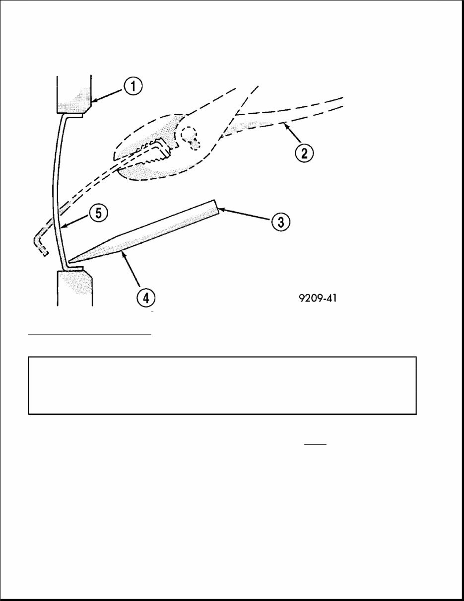
Fig. 2: Core Hole Plug Removal
Courtesy of CHRYSLER LLC
Using a blunt tool such as a drift and a hammer, strike the bottom edge of the cup plug (5). With the cup plug
rotated, grasp firmly with pliers or other suitable tool and remove plug. See Fig. 2 .
Thoroughly clean inside of cup plug hole in cylinder block or head. Be sure to remove old sealer. Lightly coat
inside of cup plug hole with Mopar® Stud and Bearing Mount. Make certain the new plug is cleaned of all oil
or grease. Using proper drive plug, drive plug into hole so that the sharp edge of the plug is at least 0.5 mm
(0.020 in.) inside the lead-in chamfer.
1 - CYLINDER BLOCK
2 - REMOVE PLUG WITH PLIERS
3 - STRIKE HERE WITH HAMMER
4 - DRIFT PUNCH
5 - CUP PLUG
CAUTION: Do not drive cup plug into the casting as restricted cooling can result and
cause serious engine problems.
It is not necessary to wait for curing of the sealant. The cooling system can be refilled and the vehicle placed in
service immediately.
ENGINE GASKET SURFACE PREPARATION
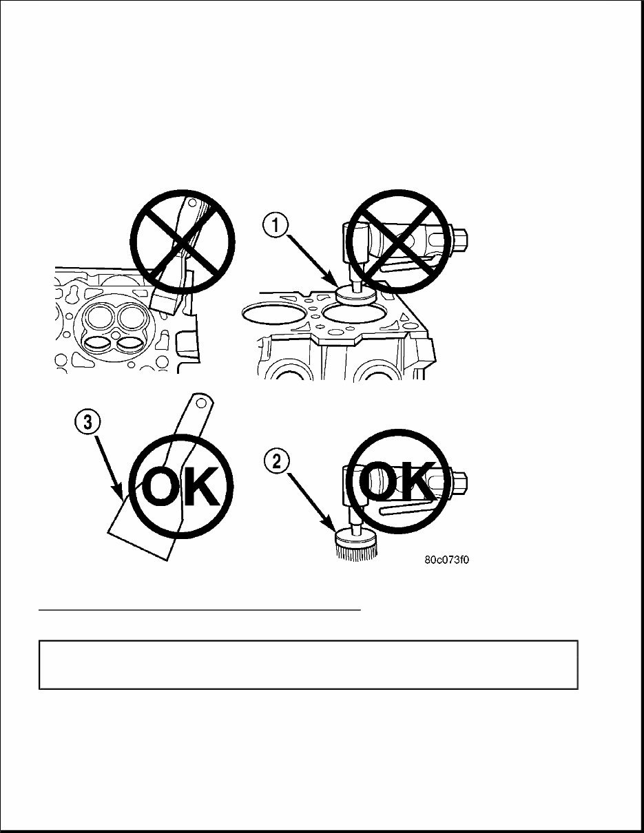
Fig. 3: View Of Proper Tool Usage For Surface Preparation
Courtesy of CHRYSLER LLC
To ensure engine gasket sealing, proper surface preparation must be performed, especially with the use of
aluminum engine components and multi-layer steel cylinder head gaskets.
Never use the following to clean gasket surfaces:
1 - ABRASIVE PAD
2 - 3M ROLOC™ BRISTLE DISC
3 - PLASTIC/WOOD SCRAPER
You're Reading a Preview
What's Included?
Fast Download Speeds
Online & Offline Access
Access PDF Contents & Bookmarks
Full Search Facility
Print one or all pages of your manual
$31.99
Viewed 67 Times Today


Secure transaction
What's Included?
Fast Download Speeds
Online & Offline Access
Access PDF Contents & Bookmarks
Full Search Facility
Print one or all pages of your manual
$31.99
This manual contains maintenance and repair procedures for the Dodge Nitro 2007.
- Dodge Nitro 2007 Service Repair Factory Manual is an electronic version of the best original maintenance manual. It can zoom in anywhere on your computer, so you can see it clearly. Your Dodge Nitro 2007 parts correspond with the number of pages printed on it in this manual, very easy to use.
- Covers the following models:
Dodge Nitro 2007 Service Repair Factory Manual
- Service Repair Factory Manual Covers:
- General Information
- Specifications
- Technical Features and Description
- Rigging Information
- Troubleshooting
- Electrical System
- Fuel System
- Power Unit
- Lower Unit
- Bracket Unit
- Maintenance
- Index
- Appendix
- ... and more
Dodge Nitro 2007 Service Repair Factory Manual is written step by step in details, so you become very easy to repair by yourself. It can save your expenses.
Do not hesitate, after your payment, you will immediately get the manual.
File Format:
- Compatible: All Versions of Windows & Mac
- Language: English
- Requirements: Adobe Reader
Tags:
- DODGE NITRO 2007 General Information
- DODGE NITRO 2007 Specifications
- DODGE NITRO 2007 Technical Features and Description
- DODGE NITRO 2007 Rigging Information
- DODGE NITRO 2007 Troubleshooting
- DODGE NITRO 2007 Electrical System
- DODGE NITRO 2007 Fuel System
- DODGE NITRO 2007 Power Unit
- DODGE NITRO 2007 Lower Unit
- DODGE NITRO 2007 Bracket Unit
- DODGE NITRO 2007 Maintenance
Dodge Nitro 2007 Service Manual


