DODGE NEON SRT-4 Service Repair Manual 2003 2004 2005
What's Included?
Lifetime Access
Fast Download Speeds
Offline Viewing
Access Contents & Bookmarks
Full Search Facility
Print one or all pages of your manual
TABLE OF CONTENTS 1.0 INTRODUCTION .........................................................1 1.1 SYSTEM COVERAGE ...............................................1 1.2 SIX-STEP TROUBLESHOOTING PROCEDURE ..........................1 2.0 IDENTIFICATION OF SYSTEM .............................................1 3.0 SYSTEM DESCRIPTION AND FUNCTIONAL OPERATION ......................1 3.1 GENERAL DESCRIPTION ............................................1 3.2 FUNCTIONAL OPERATION ...........................................2 3.2.1 FUEL CONTROL ............................................2 3.2.2 ON-BOARD DIAGNOSTICS ...................................2 3.2.3 OTHER CONTROLS .........................................5 3.2.4 PCM OPERATING MODES ..................................10 3.2.5 NON-MONITORED CIRCUITS ................................10 3.2.6 SKIS OVERVIEW ..........................................10 3.2.7 SKIM ON-BOARD DIAGNOSTICS .............................10 3.2.8 SKIS OPERATION ..........................................11 3.2.9 PROGRAMMING THE POWERTRAIN CONTROL MODULE ........11 3.2.10 PROGRAMMING THE SENTRY KEY IMMOBILIZER MODULE .....12 3.2.11 PROGRAMMING THE IGNITION KEYS TO THE SENTRY KEY IMMOBILIZER MODULE.....................................12 3.3 DIAGNOSTIC TROUBLE CODES .....................................12 3.3.1 HARD CODE ..............................................12 3.3.2 INTERMITTENT CODE ......................................13 3.3.3 STARTS SINCE SET COUNTER ..............................13 3.3.4 DISTANCE SINCE MI SET ...................................13 3.4 USING THE DRBIIIT ................................................13 3.5 DRBIIIT ERROR MESSAGES AND BLANK SCREEN .....................13 3.5.1 DRBIIIT DOES NOT POWER UP..............................14 3.5.2 DISPLAY IS NOT VISIBLE ...................................14 4.0 DISCLAIMERS, SAFETY, WARNINGS ......................................14 4.1 DISCLAIMERS.....................................................14 4.2 SAFETY ..........................................................14 4.2.1 TECHNICIAN SAFETY INFORMATION .........................14 4.2.2 VEHICLE PREPARATION FOR TESTING.......................14 4.2.3 SERVICING SUB ASSEMBLIES ..............................14 4.2.4 DRBIIIT SAFETY INFORMATION .............................14 4.3 WARNINGS AND CAUTIONS ........................................15 4.3.1 ROAD TEST WARNINGS ....................................15 4.3.2 VEHICLE DAMAGE CAUTIONS ..............................15 5.0 REQUIRED TOOLS AND EQUIPMENT .....................................15 6.0 GLOSSARY OF TERMS..................................................16 7.0 DIAGNOSTIC INFORMATION AND PROCEDURES ...........................17 COMMUNICATION *NO RESPONSE FROM PCM (PCI BUS) - NGC ..............................18 *NO RESPONSE FROM PCM (PCM SCI ONLY) - NGC ........................19 i
TABLE OF CONTENTS - Continued *NO RESPONSE FROM SENTRY KEY IMMOBILIZER MODULE ................22 *NO RESPONSE FROM TRANSMISSION CONTROL MODULE - NGC ...........24 *PCI BUS COMMUNICATION FAILURE .....................................27 DRIVEABILITY - NGC INTERMITTENT CONDITION ..............................................30 P0016-CRANKSHAFT/CAMSHAFT TIMING MISALIGNMENT....................31 P0031-O2 SENSOR 1/1 HEATER CIRCUIT LOW .............................35 P0037-O2 SENSOR 1/2 HEATER CIRCUIT LOW .............................35 P0032-O2 SENSOR 1/1 HEATER CIRCUIT HIGH .............................37 P0038-O2 SENSOR 1/2 HEATER CIRCUIT HIGH .............................37 P0033-SURGE VALVE SOLENOID CIRCUIT .................................40 P0068-MANIFOLD PRESSURE/THROTTLE POSITION CORRELATION...........42 P0071-AMBIENT TEMP SENSOR PERFORMANCE ...........................48 P0072-AMBIENT TEMP SENSOR LOW .....................................51 P0073-AMBIENT TEMP SENSOR HIGH .....................................53 P0107-MAP SENSOR LOW ...............................................55 P0108-MAP SENSOR HIGH...............................................58 P0111-INTAKEAIR TEMPERATURE SENSOR PERFORMANCE .................61 P0112-INTAKE AIR TEMPERATURE SENSOR LOW ...........................64 P0113-INTAKE AIR TEMPERATURE SENSOR HIGH ..........................66 P0116-ENGINE COOLANT TEMPERATURE PERFORMANCE...................68 P0117-ENGINE COOLANT TEMPERATURE SENSOR LOW ....................71 P0118-ENGINE COOLANT TEMPERATURE SENSOR HIGH ....................73 P0122-THROTTLE POSITION SENSOR #1 LOW .............................75 P0123-THROTTLE POSITION SENSOR #1 HIGH .............................78 P0125-INSUFFICIENT COOLANT TEMP FOR CLOSED-LOOP FUEL CONTROL . . .81 P0128-THERMOSTAT RATIONALITY .......................................83 P0129-BAROMETRIC PRESSURE OUT-OF-RANGE ..........................88 P0131-O2 SENSOR 1/1 VOLTAGE LOW ....................................92 P0137-O2 SENSOR 1/2 VOLTAGE LOW ....................................92 P0132-O2 SENSOR 1/1 VOLTAGE HIGH ....................................95 P0138-O2 SENSOR 1/2 VOLTAGE HIGH ....................................95 P0133-O2 SENSOR 1/1 SLOW RESPONSE .................................98 P0139-O2 SENSOR 1/2 SLOW RESPONSE .................................98 P0135-O2 SENSOR 1/1 HEATER PERFORMANCE ..........................100 P0141-O2 SENSOR 1/2 HEATER PERFORMANCE ..........................100 P0171-FUEL SYSTEM 1/1 LEAN ..........................................103 P0172-FUEL SYSTEM 1/1 RICH ..........................................108 P0201-FUEL INJECTOR #1 ..............................................112 P0202-FUEL INJECTOR #2 ..............................................112 P0203-FUEL INJECTOR #3 ..............................................112 P0204-FUEL INJECTOR #4 ..............................................112 P0234-OVERBOOST PERFORMANCE .....................................115 P1106-BARO SOLENOID PERFORMANCE .................................115 P1188 TIP SENSOR PERFORMANCE .....................................115 P0243-WASTEGATE SOLENOID CIRCUIT ..................................119 P0300-MULTIPLE CYLINDER MISFIRE ....................................122 P0301-CYLINDER #1 MISFIRE ...........................................122 P0302-CYLINDER #2 MISFIRE ...........................................122 P0303-CYLINDER #3 MISFIRE ...........................................122 P0304-CYLINDER #4 MISFIRE ...........................................122 P0315-NO CRANK SENSOR LEARNED ....................................130 ii
TABLE OF CONTENTS - Continued P0325-KNOCK SENSOR #1 CIRCUIT .....................................132 P0335-CRANKSHAFT POSITION SENSOR CIRCUIT .........................135 P0339-CRANKSHAFT POSITION SENSOR INTERMITTENT ...................140 P0340-CAMSHAFT POSITION SENSOR CIRCUIT ...........................144 P0344-CAMSHAFT POSITION SENSOR INTERMITTENT .....................149 P0420-CATALYTIC 1/1 EFFICIENCY .......................................153 P0440-GENERAL EVAP SYSTEM FAILURE.................................154 P0441-EVAP PURGE SYSTEM PERFORMANCE ............................159 P0442-EVAP SYSTEM MEDIUM LEAK .....................................161 P0455-EVAP SYSTEM LARGE LEAK ......................................161 P0443-EVAP PURGE SOLENOID CIRCUIT .................................166 P0452-NVLD PRESSURE SWITCH SENSE CIRCUIT LOW ....................169 P0453-NVLD PRESSURE SWITCH SENSE CIRCUIT HIGH....................172 P0456-EVAP SYSTEM SMALL LEAK ......................................174 P0461-FUEL LEVEL SENSOR #1 PERFORMANCE ..........................176 P0462-FUEL LEVEL SENSOR #1 LOW ....................................178 P0463-FUEL LEVEL SENSOR #1 HIGH ....................................178 P0480-COOLING FAN 1 CONTROL CIRCUIT ...............................179 P0481-COOLING FAN 2 CONTROL CIRCUIT (NON-TURBO) ..................179 P0481-COOLING FAN 2 CONTROL CIRCUIT (TURBO) .......................181 P0498-NVLD CANISTER VENT VALVE SOLENOID CIRCUIT LOW ..............184 P0499-NVLD CANISTER VENT VALVE SOLENOID CIRCUIT HIGH .............185 P0501-VEHICLE SPEED SENSOR #1 PERFORMANCE (AUTO TRANS) .........187 P0501-VEHICLE SPEED SENSOR #1 PERFORMANCE (MANUAL TRANS) ......188 P0506-IDLE SPEED LOW PERFORMANCE ................................190 P0507-IDLE SPEED HIGH PERFORMANCE ................................190 P0519-IDLE SPEED PERFORMANCE .....................................190 P0508-IAC VALVE SENSE CIRCUIT LOW ..................................192 P0509-IAC VALVE SENSE CIRCUIT HIGH ..................................195 P0513-INVALID SKIM KEY ...............................................197 P0516-BATTERY TEMPERATURE SENSOR LOW ...........................199 P0517-BATTERY TEMPERATURE SENSOR HIGH ...........................201 P0522-OIL PRESSURE SENSOR LOW ....................................203 P0551-POWER STEERING SWITCH PERFORMANCE .......................205 P0562-BATTERY VOLTAGE LOW .........................................207 P0563-BATTERY VOLTAGE HIGH.........................................210 P0572-BRAKE SWITCH #1 CIRCUIT LOW..................................212 P0573-BRAKE SWITCH #1 CIRCUIT HIGH .................................214 P0581-SPEED CONTROL SWITCH #1 HIGH ................................216 P0582-SPEED CONTROL VACUUM SOLENOID CIRCUIT .....................218 P0586-SPEED CONTROL VENT SOLENOID CIRCUIT ........................220 P0594-SPEED CONTROL SERVO POWER CIRCUIT .........................222 P0600-SERIAL COMMUNICATION LINK....................................225 P0601-INTERNAL MEMORY CHECKSUM INVALID...........................225 P0622-GENERATOR FIELD CONTROL CIRCUIT ............................226 P0627-FUEL PUMP RELAY CIRCUIT ......................................228 P0630-VIN NOT PROGRAMMED IN PCM ..................................230 P0632-ODOMETER NOT PROGRAMMED IN PCM ...........................231 P0633-SKIM KEY NOT PROGRAMMED IN PCM.............................232 P0645-A/C CLUTCH RELAY CIRCUIT .....................................233 P0660-MANIFOLD TUNE VALVE SOLENOID CIRCUIT ........................235 P0685-ASD RELAY CONTROL CIRCUIT ...................................238 P0688-ASD RELAY SENSE CIRCUIT LOW .................................240 iii
TABLE OF CONTENTS - Continued P0700-TRANSMISSION CONTROL SYSTEM/READ TRANSMISSION DTCS ON THE DRBIIIT .......................................................243 P0833-CLUTCH RELEASED SWITCH CIRCUIT .............................244 P0850-PARK/NEUTRAL SWITCH PERFORMANCE ..........................246 P1105-TIP SENSOR SOLENOID CIRCUIT ..................................247 P1115-GENERAL TEMP SENSOR PERFORMANCE ..........................249 P1189-TIP SENSOR CIRCUIT LOW .......................................253 P1190-TIP SENSOR CIRCUIT HIGH .......................................256 P1593-SPEED CONTROL SWITCH STUCK .................................259 P1602-PCM NOT PROGRAMMED ........................................262 P1603-PCM INTERNAL DUAL-PORT RAM COMMUNICATION .................263 P1604-PCM INTERNAL DUAL-PORT RAM READ/WRITE INTEGRITY FAILURE . . .263 P1607-PCM INTERNAL SHUTDOWN TIMER RATIONALITY ...................263 P1696-EEPROM MEMORY WRITE DENIED/INVALID .........................264 P1697-EMR (SRI) MILEAGE NOT STORED .................................264 P1854-TIP BARO OUT OF RANGE ........................................266 P2074-MANIFOLD PRESSURE/THROTTLE POSITION CORRELATION - HIGH FLOW/VACUUM LEAK ..................................................270 P2096-DOWN STREAM FUEL SYSTEM 1/2 LEAN ...........................276 P2097-DOWN STREAM FUEL SYSTEM 1/2 RICH ...........................276 P2302-IGNITION COIL #1 SECONDARY CIRCUIT-INSUFFICIENT IONIZATION . . .279 P2305-IGNITION COIL #2 SECONDARY CIRCUIT-INSUFFICIENT IONIZATION . . .279 P2503-CHARGING SYSTEM VOLTAGE LOW ...............................282 U0101-NO TRANSMISSION BUS MESSAGE................................285 U0155-NO CLUSTER BUS MESSAGE .....................................287 U0168-NO SKIM BUS MESSAGES ........................................288 U110C-NO FUEL LEVEL BUS MESSAGE ..................................290 *CHECKING PCM POWER AND GROUND CIRCUITS ........................292 *CHECKING RAD FAN HIGH SPEED OPERATION (TURBO) ..................293 *CHECKING RAD FAN LOW SPEED OPERATION (TURBO) ...................295 *CHECKING RADIATOR FAN RELAY OUTPUT ..............................298 *CHECKING THE A/C RELAY OUTPUT ....................................300 SENTRY KEY IMMOBILIZER ANTENNA FAILURE ....................................................302 COP FAILURE .........................................................302 EEPROM FAILURE .....................................................302 INTERNAL FAULT ......................................................302 RAM FAILURE.........................................................302 SERIAL LINK INTERNAL FAULT ..........................................302 STACK OVERFLOW FAILURE............................................302 PCM STATUS FAILURE .................................................304 SERIAL LINK EXTERNAL FAULT .........................................304 ROLLING CODE FAILURE ...............................................306 VIN MISMATCH ........................................................306 TRANSPONDER COMMUNICATION FAILURE ..............................308 TRANSPONDER CYCLIC REDUNDANCY CHECK (CRC) FAILURE .............308 TRANSPONDER ID MISMATCH ..........................................308 TRANSPONDER RESPONSE MISMATCH ..................................308 STARTING *CHECKING FUEL DELIVERY ............................................311 *CHECKING FUEL PRESSURE LEAK DOWN ...............................314 iv
TABLE OF CONTENTS - Continued *ENGINE CRANKS DOES NOT START ....................................315 *ENGINE CRANKS DOES NOT START - 1.6L ...............................323 *NO CRANK CONDITION................................................330 *NO RESPONSE FROM PCM WITH A NO START CONDITION ................333 *START AND STALL CONDITION .........................................334 VERIFICATION TESTS VERIFICATION TESTS ..................................................337 8.0 COMPONENT LOCATIONS ..............................................345 8.1 CONTROL MODULES AND PDC.....................................345 8.2 CONTROLS AND SOLENOIDS ......................................345 8.3 DATA LINK CONNECTOR ..........................................347 8.4 SENSORS .......................................................347 8.5 FUEL SYSTEM ...................................................349 8.6 SWITCHES/GAUGES ..............................................349 9.0 CONNECTOR PINOUTS ................................................351 A/C COMPRESSOR CLUTCH - BLACK 2 WAY ..............................351 A/C HIGH PRESSURE SWITCH - BLACK 2 WAY ............................351 A/C LOW PRESSURE SWITCH (2.0L LHD) - DK. GREEN 2 WAY ...............351 A/C LOW PRESSURE SWITCH (2.4L TURBO) - DK. GREEN 2 WAY ............351 A/C LOW PRESSURE SWITCH (RHD) - BLACK 2 WAY .......................352 AMBIENT TEMPERATURE SENSOR - BLACK 2 WAY ........................352 BATTERYTEMPERATURE SENSOR - BLACK 2 WAY ........................352 BRAKE LAMP SWITCH - BLACK 6 WAY ...................................352 CAMSHAFT POSITION SENSOR - BLACK 3 WAY ...........................353 CLOCKSPRING - GREEN 7 WAY .........................................353 CLUTCH INTERLOCK/UPSTOP SWITCH (MTX) - BLACK 3 WAY ...............353 CRANKSHAFT POSITION SENSOR - BLACK 3 WAY .........................353 DATALINK CONNECTOR - WHITE 16 WAY ................................354 ENGINE COOLANT TEMP SENSOR (2.0L) - BLACK 2 WAY ...................354 ENGINE COOLANT TEMP SENSOR (2.4L TURBO) - BLACK 2 WAY ............354 ENGINE OILPRESSURE SWITCH - LT. GREEN 2 WAY ......................354 EVAP/PURGE SOLENOID - BLACK 2 WAY .................................355 FUEL INJECTOR NO. 1 - BLACK 2 WAY ...................................355 FUEL INJECTOR NO. 2 - BLACK 2 WAY ...................................355 FUEL INJECTOR NO. 3 - BLACK 2 WAY ...................................355 FUEL INJECTOR NO. 4 - BLACK 2 WAY ...................................355 FUELPUMP MODULE - LT. GRAY 4 WAY ..................................356 FUSES (FB LHD) ......................................................358 FUSES (FB RHD) ......................................................360 GENERATOR (2.0L) - BLACK 2 WAY ......................................360 GENERATOR (2.4LTURBO) - LT. GRAY 2 WAY .............................360 GENERATOR (GENERATOR SIDE) .......................................361 IDLE AIR CONTROL MOTOR (2.0L/2.4L TURBO) - BLACK 2 WAY ..............361 IGNITION COIL - BLACK 3 WAY ..........................................361 INLET AIR TEMPERATURE SENSOR - BLACK 2 WAY........................361 INSTRUMENT CLUSTER - BLACK 26 WAY .................................362 KNOCK SENSOR - BLACK 2 WAY ........................................362 MANIFOLD ABSOLUTE PRESSURE SENSOR (2.0L) - GRAY 3 WAY ............363 v
TABLE OF CONTENTS - Continued MANIFOLD ABSOLUTE PRESSURE SENSOR (2.4L TURBO) - NATURAL 3 WAY .363 MANIFOLD TUNING VALVE SOLENOID (RT) - BLACK 2 WAY .................363 OXYGEN SENSOR 1/1 UPSTREAM - BLACK 4 WAY .........................363 OXYGEN SENSOR 1/2 DOWNSTREAM - BLACK 4 WAY .....................364 OXYGEN SENSOR CONNECTOR (COMPONENT SIDE) - 4 WAY ..............364 FUSES (PDC) .........................................................366 A/C COMPRESSOR CLUTCH RELAY......................................366 AUTOMATIC SHUT DOWN RELAY ........................................366 FUEL PUMP RELAY ....................................................367 MANIFOLD TUNING VALVE RELAY (RT) ...................................367 RADIATOR FAN CONTROL RELAY (2.4L TURBO) ...........................367 RADIATOR FAN HIGH RELAY (2.4L TURBO) ...............................367 RADIATOR FAN RELAY (2.0L) ............................................367 STARTER MOTOR RELAY ...............................................367 POWERTRAIN CONTROL MODULE C1 - BLACK 38 WAY.....................368 POWERTRAIN CONTROL MODULE C2 (2.0L) - ORANGE 38 WAY .............369 POWERTRAIN CONTROL MODULE C3 - WHITE 38 WAY .....................370 RADIATOR FAN MOTOR (2.0L) - BLACK 2 WAY.............................371 RADIATOR FAN MOTOR (2.4LTURBO) - BLACK 4 WAY ......................371 SENTRY KEY IMMOBILIZER MODULE - BLACK 6 WAY ......................371 SPEED CONTROL SERVO - BLACK 4 WAY ................................371 SURGE SOLENOID (2.4L TURBO) - BLACK 2 WAY ..........................372 THROTTLE INLET PRESSURE SENSOR (2.4L TURBO) - NATURAL 3 WAY ......372 THROTTLE INLET PRESSURE SOLENOID (2.4L TURBO) - BLACK 2 WAY ......372 THROTTLE POSITION SENSOR (2.0L) - BLACK 3 WAY ......................372 THROTTLE POSITION SENSOR (2.4L TURBO) - NATURAL 3 WAY .............373 TURBO BOOST GAUGE LAMP (2.4L TURBO) - NATURAL 2 WAY ..............373 VEHICLE SPEED SENSOR - BLACK 3 WAY ................................373 WASTEGATE SOLENOID (2.4L TURBO) - BLACK 2 WAY .....................373 10.0 SCHEMATIC DIAGRAMS................................................375 10.1 2004 PL 2.0L ENGINE .............................................375 10.2 2004 SRT-4 2.4L ENGINE ..........................................377 11.0 CHARTS AND GRAPHS ................................................379 vi
NOTE (NGC) The 2004 PL is equipped with the Powertrain Control Module and Transmission Control Module combined in a single control module. This module is the Next Generation Controller (NGC) for DaimlerChrysler and will be referred to as the Powertrain Control Module (PCM). The PCM has four color coded connectors C1 through C4, (C1 - BLK, C2 - ORANGE, C3 - WHITE, C4 - GREEN), with each connector containing 38 pins. Two tools are required to diagnose and repair the PCM terminals and harness connectors: 1. Miller #3638 Terminal Removal Pick must be used to release the connector terminals or harness and connector damage will occur. 2. Miller #8815 Pinout Box must be used to probe the PCM terminals or terminal damage will occur. 1.0 INTRODUCTION The procedures contained in this manual include specifications, instructions, and graphics needed to diagnose the PCM Powertrain System. The diag- nostics in this manual are based on the failure condition or symptom being present at time of diagnosis. Please follow the recommendations below when choosing your diagnostic path. 1. First make sure the DRBIIIt is communicating with the appropriate modules; ie., if the DRBIIIt displays a No Response condition, you must diagnose this first before proceeding. 2. Read DTC’s (diagnostic trouble codes) with the DRBIIIt. 3. If no DTC’s are present, identify the customer complaint. 4. Once the DTC or customer complaint is identi- fied, locate the matching test in the Table of Contents and begin to diagnose the symptom. All component location views are in Section 8.0. All connector pinouts are in Section 9.0. All system schematics are in Section 10.0. An * placed before the symptom description indi- cates a customer complaint. When repairs are required, refer to the appropri- ate service information for the proper removal and repair procedure. Diagnostic procedures change every year. New diagnostic systems may be added; carryover sys- tems may be enhanced. READ THIS DIAGNOSTIC INFORMATION BEFORE TRYING TO DIAG- NOSE A VEHICLE CODE. It is recommended that you review the entire diagnostic information to become familiar with all new and changed diagnos- tic procedures. If you have any comments or recommendations after reviewing the diagnostic information, please fill out the form at the back of the book and mail it back to us. 1.1 SYSTEM COVERAGE This diagnostic procedures manual covers the 2003 PL vehicle equipped with the 2.0L and 2.4L Turbo Engines. 1.2 SIX-STEP TROUBLESHOOTING PROCEDURE Diagnosis of the powertrain control module (PCM) is done in six basic steps: • verification of complaint • verification of any related symptoms • symptom analysis • problem isolation • repair of isolated problem • verification of proper operation 2.0 IDENTIFICATION OF SYSTEM The Powertrain Control Module (PCM) monitors and controls: • Fuel System • Idle Air Control System • Ignition System • Charging System • Speed Control System • Cooling system 3.0 SYSTEM DESCRIPTION AND FUNCTIONAL OPERATION 3.1 GENERAL DESCRIPTION These Sequential Fuel Injection (SFI) engine sys- tems have the latest in technical advances. The OBDII/Euro Stage III OBD diagnostics incorpo- rated with the Powertrain Control Module (PCM) are intended to assist the field technician in repair- ing vehicle problems by the quickest means. 1 GENERAL INFORMATION
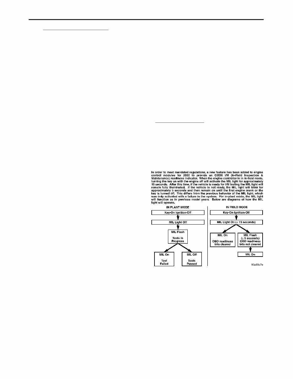
3.2 FUNCTIONAL OPERATION 3.2.1 FUEL CONTROL The PCM controls the air/fuel ratio of the engine by varying fuel injector on time. Air flow is calcu- lated using the speed density method using enigne speed, manifold absolute pressure, and air temper- ature change. Different fuel calculation strategies are used de- pending on the operational state of the engine. During crank mode, a longer pulse width fuel pulse is delivered followed by fuel pulses determined by a crank time strategy. Cold engine operation is deter- mined via an open loop strategy until the O2 sensors have reached operating temperature. At this point, the strategy enters a closed loop mode where fuel requirements are based upon the state of the O2 sensors, engine speed, MAP, throttle posi- tion, air temperature, battery voltage, and coolant temperature. 3.2.2 ON-BOARD DIAGNOSTICS The PCM has been programmed to monitor many different circuits of the fuel injection system. This monitoring is called on-board diagnosis. Certain criteria, or arming conditions, must be met for a trouble code to be entered into the PCM memory. The criteria may be a range of: engine rpm, engine temperature, and/or input voltage to the PCM. If a problem is sensed with a monitored circuit, and all of the criteria or arming conditions are met, then a trouble code will be stored in the PCM. It is possible that a trouble code for a monitored circuit may not be entered into the PCM memory even though a malfunction has occurred. This may happen because one of the trouble code criteria have not been met. The PCM compares input signal voltages from each input device with specifications (the estab- lished high and low limits of the range) that are programmed into it for that device. If the input voltage is not within specifications and other trou- ble code criteria are met, a trouble code will be stored in the PCM memory. The On Board Diagnostics have evolved to the second Generation of Diagnostics referred to as OBDII/Euro Stage III OBD. These OBDII/Euro Stage III OBD Diagnostics control the functions necessary to meet the requirements of California OBDII, Federal OBD regulation and European reg- ulation. These requirements specify the inclusion of a Malfunction Indicator Light (MIL) located on the instrument panel. The purpose of the MIL is to inform the vehicle operator in the event of a mal- function of any emission system or component fail- ure. MIL Lamp Strategy I/M Readiness OK to test = Key On Engine OFF – MIL Lamp will remain on until the engine is started or Ignition is turned off. I/M not ready for testing = Key On Engine OFF – MIL Lamp on solid for (15) seconds then MIL Lamp will flash on/off for (5) seconds then it will remain on until the vehicle is started or the Ignition is turned off. 2 GENERAL INFORMATION
OBD II/EURO STAGE III OBD MONITOR INFORMATION Comprehensive Major Monitors Major Monitors Components Non Fuel Control Fuel Control Monitor & Non Misfire & Misfire Run constantly Run Once Per Trip Run Constantly Includes All Engine Hardware Monitors Entire Emission Monitors Entire System - Sensors, Switches, System Solenoids, etc. One Trip Faults - Turns On Two Trip Faults - Turns On Two Trip Faults - Turns On The MIL and Sets DTC After The MIL and Sets DTC After The MIL and Sets DTC After One Failure Two Consecutive Failures Two Consecutive Failures Priority 3 Priority 1 or 3 Priority 2 or 4 All Checked For Continuity Done Stop Testing = Yes Fuel Control Monitor Open Monitors Fuel Control Short To Ground Oxygen Sensor Heater System For: Short To Voltage Oxygen Sensor Response Fuel System Lean Fuel System Rich Inputs Checked For Requires 3 Consecutive Rationality Catalytic Converter Fuel System Good Trips To Efficiency Except EWMA Extinguish The MIL Outputs Checked For - up to 6 tests per trip Functionality and a one trip fault Misfire Monitor Evaporative Emission Monitors For Engine Misfire System at: 1000 RPM Counter (Type B) **200 RPM Counter (Type A) Requires 3 Consecutive Requires 3 Consecutive Requires 3 Consecutive Global/Alternate Good Trips Global Good Trips Misfire Good Trips to Extinguish the MIL* to Extinguish the MIL* To Extinguish the MIL *40 Warm Up Cycles are required to erase **Type A misfire is a two DTC’s after the MIL has been extinguished. trip failure. The MIL will illuminate and blink at the first failure. 3 GENERAL INFORMATION
OBDII Monitor Run Process NGC Vehicle The following procedure has been established to assist Technicians in the field with enabling and running OBDII Monitors. The order listed in the following procedure is intended to allow the techni- cian to effectively complete each monitor and to set the CARB Readiness Status in the least time pos- sible. **NOTE** A. Once the monitor run process has begun, do not turn off the ignition. By turning the igni- tion key off, monitor enabling conditions will be lost. Only the 02 Heater Monitor runs after key off. B. By performing a Battery Disconnect, or Se- lecting Erase DTCs, the CARB Readiness and all additional OBD information will be cleared. Monitor Preliminary Checks: 1. Plug a DRBIII into the vehicle’s DLC. 2. Turn the ignition, KEY ON–ENGINE OFF. Watch for MIL lamp illumination during the bulb check. MIL lamp must have illuminated, if not, repair MIL lamp. 3. On the DRB III Select #1 DRB III Standalone. 4. Select #1 1998-2004 Diagnostics 5. Select #1 Engine 6. Select #2 DTCs and Related Functions 7. Select #1 Read DTCs *Verify that No Emissions Related DTCs are Present. *If an Emissions DTC is Present, the OBD II Monitors may not run and the CARB Readiness will not update. *The Emissions related DTC, will need to be repaired, then cleared. By clearing DTCs, the OBD Monitors will need to be run and completed to set the CARB Readiness Status. 8. Return to Engine Select Function Menu and Select #9, OBD II Monitors. 9. Select #2 CARB Readiness Status. Do all the CARB Readiness Status Locations read YES? *YES, then all monitors have been completed and this vehicle is ready to be I/M or Emission Tested. *NO, then the following procedure needs to be followed to run/complete all available monitors. **NOTE** A. Only the monitors, which are not YES in the CARB Readiness Status, need to be completed. B. Specific criteria need to be met for each monitor. Each monitor has a Pre-Test screen to assist in running the monitor. For additional informa- tion, refer to the Chrysler Corporation Technical Training Workbook title On Board Diagnostics, part number 81-699-97094. The most efficient order to run the monitors has been outlined below, including suggestions to aid the process. A. NATURAL VACUUM LEAK DETECTION WITH PURGE MONITOR This monitor requires a cool down cycle, usually an overnight soak for at least 8 hours without the engine running. The ambient temperature must decrease overnight – parking the vehicle outside is advised. To run this test the fuel level must be between 15-85% full. For the monitor run condi- tions select the EVAP MON PRE-TEST in the DRB IIIt, OBD II Monitors Menu. The Purge mon- itor will run if the small leak test reports a pass. Criteria for NVLD monitor. 1. Engine off time greater than one hour 2. Fuel Level between 15% and 85% 3. Start Up ECT and IAT within 10°C (18°F). 4. Vehicle started and run until Purge Monitor reports a result. NOTE: If the vehicle does not report a result and the conditions were correct, it may take up to two weeks to fail the small leak monitor. DO NOT use this test to attempt to determine a fault. Use the appropriate service information procedure for finding a small leak. If there are no faults and the conditions are correct this test will run and report a pass. Note the Small leak test can find leaks less than 10 thousandths of an inch. If a small leak is present it takes approximately one week of normal driving to report a failure. B. CATALYST/O2 MONITOR With NGC, Catalyst and O2 Monitor information are acquired and processed at the same time. Most vehicles will need to be driven at highway speed (<50 mph) for a few minutes. Some trucks run the monitor at idle in drive. If the vehicle is equipped with a manual transmission, using 4 th gear may assist in meeting the monitor running criteria. For the monitor run conditions, select the BANK 1 CAT MON PRE-TEST in the DRB IIIt, OBD II Monitors Menu. C. EGR MONITOR The EGR monitor now runs in a closed throttle decel or at idle on a warm vehicle. However, it is necessary to maintain the TPS, Map and RPM ranges to allow the monitor to complete itself. For 4 GENERAL INFORMATION
This is a comprehensive repair manual / service manual for the 2003-2005 Dodge Neon Srt-4. It encompasses every intricate detail of the car.
Models Covered:
NEON RHD & LHD
Line:
Economy
Low line
High line
Premium
Sport
Special
Engine:
2.0L 4Cyl 16v SOHC Gasoline
2.0L 4Cyl 16v High Performance Gasoline
2.0L 4Cyl 16v DOHC High Output Turbo
The manual allows you to zoom in to view detailed parts and then print out any pages you need, without getting grease on any pages. It covers in detail the years 2003-2005, with over 2000 pages, all for easy, detailed viewing.
Main categories covered in the manual:
ENGINE OVERHAUL AND REBUILDING
BRAKES
SUNROOF
TIMING BELT REPLACEMENT
TROUBLE CODES
WIRING DIAGRAMS
TROUBLESHOOTING AND DIAGNOSTICS
COMPUTER DIAGNOSTIC TROUBLE TREE CHARTS
ENGINE PERFORMANCE
FRONT END AND ALIGNMENT PROCEDURES AND SPECIFICATIONS
SUSPENSION
TRANSMISSION REMOVAL AND INSTALLATION
AIR CONDITIONING SERVICE AND CAPACITIES
TRANSMISSION IN CAR SERVICING
COMPUTER DIAGNOSTIC CODES
FIRING ORDERS
DETAILED SPECIFICATIONS ON EVERY MODEL COVERED
FACTORY MAINTENANCE SCHEDULES AND CHARTS
SERPENTINE BELT ROUTINGS WITH DIAGRAMS
TIMING BELT SERVICE PROCEDURES
BRAKE SERVICING PROCEDURES
DRIVING CONCERNS
COMPLETE TORQUE SPECIFICATIONS
U-JOINT AND CV-JOINT SERVICE PROCEDURES
REPAIR PROCEDURES
COMPLETE WIRING DIAGRAMS
HUNDREDS OF ILLUSTRATIONS
VACUUM DIAGRAMS
AND MORE...
Format: PDF
Language: English
Printable: Yes
Compatible: All Versions of Windows & Mac
Requirements: Adobe Reader
We provide various Service manual / Workshop Manual / Repair Manual / Owners Manual for various brands of cars and motorcycles.
Instant access with no shipping cost and no need to wait for a CD-ROM.
This Repair Manual covers the same information that Professional Technicians and Mechanics have. It contains everything needed to repair, maintain, rebuild, refurbish, or restore the vehicle.
This Service Repair Manual also contains illustrations, diagrams, specifications, step by step instructions, pictures, procedures, and much more.
Tons of pictures and diagrams are included for easy reference. All pages are printable, making it convenient to take into the garage or workshop.
Save money by doing your own repairs with these very easy to follow, step-by-step instructions!
Instant access means no shipping cost or waiting for a CD to arrive in the mail. You will receive this manual today via instant access on completion of payment via our secure payment processor. We accept all major credit/debit cards/PayPal.
Recently Viewed
5,521,897Happy Clients
2,594,462eManuals
1,120,453Trusted Sellers
15Years in Business
Price:
Actual Price:
DODGE NEON SRT-4 Service Repair Manual 2003 2004 2005