

2000 Dodge Durango Service Repair Manual
What's Included?
Fast Download Speeds
Offline Viewing
Access Contents & Bookmarks
Full Search Facility
Print one or all pages of your manual
GROUP TAB LOCATOR
Introduction
0
Lubrication and Maintenance
2
Suspension
3
Differential and Driveline
5
Brakes
7
Cooling System
8A
Battery
8B
Starting Systems
8C
Charging System
8D
Ignition System
8E
Instrument Panel Systems
8F
Audio Systems
8G
Horn Systems
8H
Speed Control System
8J
Turn Signal and Hazard Warning Systems
8K
Wiper and Washer Systems
8L
Lamps
8M
Passive Restraint Systems
8N
Electrically Heated Systems
8O
Power Distribution System
8P
Power Lock Systems
8Q
Vehicle Theft/Security Systems
8R
Power Seat System
8S
Power Window Systems
8T
Power Mirror Systems
8U
Chime/Buzzer Warning Systems
8V
Overhead Console Systems
8W
Wiring Diagrams
9
Engine
11
Exhaust System
13
Frame and Bumpers
14
Fuel System
19
Steering
21
Transmission and Transfer Case
22
Tires and Wheels
23
Body
24
Heating and Air Conditioning
25
Emission Control Systems
Component and System Index
Service Manual Comment Forms (Rear of Manual)

INTRODUCTION
TABLE OF CONTENTS
page page
DESCRIPTION AND OPERATION
VEHICLE IDENTIFICATION NUMBER (VIN)
PLATE ................................ 1
VEHICLE SAFETY CERTIFICATION LABEL ...... 2
INTERNATIONAL SYMBOLS ................. 2
FASTENER IDENTIFICATION ................. 3
FASTENER USAGE ........................ 6
THREADED HOLE REPAIR .................. 6
METRIC SYSTEM ......................... 6
TORQUE REFERENCES ..................... 6
DESCRIPTION AND OPERATION
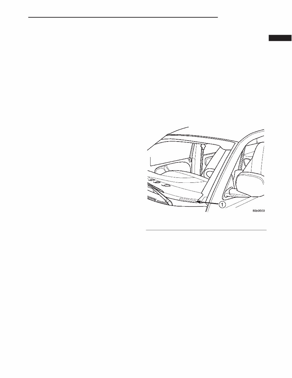
VEHICLE IDENTIFICATION NUMBER (VIN)
PLATE
The Vehicle Identification Number (VIN) plate is
attached to the top left side of the instrument panel
(Fig. 1). The VIN contains 17 characters that provide
data concerning the vehicle. Refer to the decoding
chart to determine the identification of a vehicle.
Fig. 1 Vehicle Identification Number (VIN)
1 – VIN
DN INTRODUCTION 1
VIN DECODING INFORMATION
POSITION INTERPRETATION CODE = DESCRIPTION
1 Country of Origin 1= USA
2 Make B = Dodge
3 Vehicle Type 4 = Multipurpose Passenger Vehicle
4 Gross Vehicle Weight Rating H = 6001-7000 lbs.
5 Vehicle Line
R = Durango 4x2
S = Durango 4x4
6 Series 2 = Durango
7 Body Style 8 = Sport Utility 4 Door
8 Engine
N=4.7L
Y=5.2L
Z=5.9L
9 Check Digit
10 Model Year Y=2000
11 Assembly Plant F = Newark Assembly
12 Thru 17 Vehicle Build Sequence Assembly Sequence
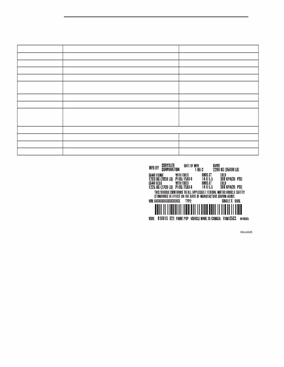
VEHICLE SAFETY CERTIFICATION LABEL
A vehicle safety certification label (Fig. 2) is
attached to every DaimlerChrysler Corporation vehi-
cle. The label certifies that the vehicle conforms to all
applicable Federal Motor Vehicle Safety Standards.
The label also lists:
• Month and year of vehicle manufacture.
• Gross Vehicle Weight Rating (GVWR). The gross
front and rear axle weight ratings (GAWR’s) are
based on a minimum rim size and maximum cold tire
inflation pressure.
• Vehicle Identification Number (VIN).
• Type of vehicle.
• Type of rear wheels.
• Bar code.
• Month, Day and Hour (MDH) of final assembly.
• Paint and Trim codes.
• Country of origin.
The label is located on the driver-side door shut-
face.
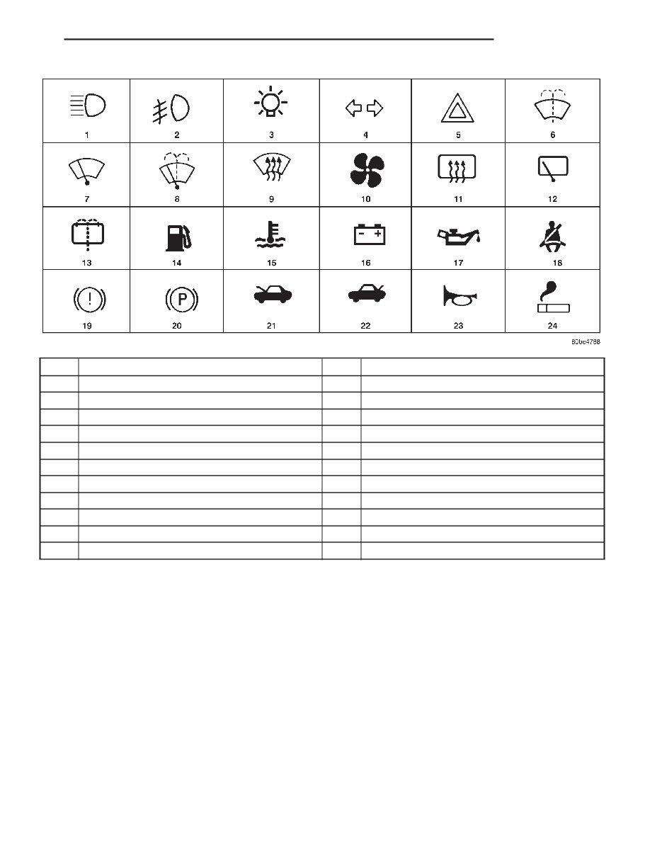
INTERNATIONAL SYMBOLS
DESCRIPTION
The graphic symbols illustrated in the following
International Control and Display Symbols Chart are
used to identify various instrument controls. The
symbols correspond to the controls and displays that
are located on the instrument panel.
Fig. 2 Vehicle Safety Certification Label—Typical
2 INTRODUCTION DN
DESCRIPTION AND OPERATION (Continued)
FASTENER IDENTIFICATION
DESCRIPTION
GRADE/CLASS IDENTIFICATION
The SAE bolt strength grades range from grade 2
to grade 8. The higher the grade number, the greater
the bolt strength. Identification is determined by the
line marks on the top of each bolt head. The actual
bolt strength grade corresponds to the number of line
marks plus 2. The most commonly used metric bolt
strength classes are 9.8 and 10.9. The metric
strength class identification number is imprinted on
the head of the bolt. The higher the class number,
the greater the bolt strength. Some metric nuts are
imprinted with a single-digit strength class on the
nut face. Refer to the Fastener Identification and
Fastener Strength Charts.
1 High Beam 13 Rear Window Washer
2 Fog Lamps 14 Fuel
3 Headlamp, Parking Lamps, Panel Lamps 15 Engine Coolant Temperature
4 Turn Warning 16 Battery Charging Condition
5 Hazard Warning 17 Engine Oil
6 Windshield Washer 18 Seat Belt
7 Windshield Wiper 19 Brake Failure
8 Windshield Wiper and Washer 20 Parking Brake
9 Windscreen Demisting and Defrosting 21 Front Hood
10 Ventilating Fan 22 Rear hood (Decklid)
11 Rear Window Defogger 23 Horn
12 Rear Window Wiper 24 Lighter
DN INTRODUCTION 3
DESCRIPTION AND OPERATION (Continued)
You're Reading a Preview
What's Included?
Fast Download Speeds
Offline Viewing
Access Contents & Bookmarks
Full Search Facility
Print one or all pages of your manual
$31.99
$41.99
Viewed 53 Times Today


Secure transaction
What's Included?
Fast Download Speeds
Offline Viewing
Access Contents & Bookmarks
Full Search Facility
Print one or all pages of your manual
$31.99
$41.99
This Service Repair Manual is an essential resource for anyone working on a 2000 Dodge Durango, providing high-quality diagrams and instructions for car service and repair. Whether you're a professional mechanic or a DIY enthusiast, this manual covers Durango 4x2, Durango 4x4, and Sport Utility 4 Door models, as well as 4.7L, 5.2L, and 5.9L engines.
- Introduction
- Lubrication & Maintenance
- Suspension
- Differential & Driveline
- Brakes
- Clutch
- Cooling
- Audio
- Chime/Buzzer
- Electronic Control Modules
- Engine Systems
- Heated Systems
- Horn
- Ignition Control
- Instrument Cluster
- Lamps
- Message Systems
- Power Systems
- Restraints
- Speed Control
- Vehicle Theft Security
- Wipers/Washers
- Wiring
- Engine
- Exhaust System
- Frame & Bumpers
- Fuel System
- Steering
- Automatic Transmission
- Tires/Wheels
- Body
- Heating & Air Conditioning
- Emissions Control
- Component and System Index
This Service Repair Manual is available in .PDF format, compatible with all versions of Windows & Mac, and requires Adobe Reader. It's an instant download, saving you time and money on postage and packaging. Get your copy now and keep your Dodge Durango in top condition!


