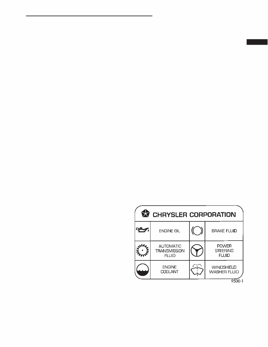
LUBRICATION AND MAINTENANCE TABLE OF CONTENTS page page LUBRICANTS AND CAPACITIES ............... 1 MAINTENANCE SCHEDULES ................. 4 JUMP STARTING, TOWING AND HOISTING .... 10 LUBRICANTS AND CAPACITIES TABLE OF CONTENTS page page SERVICE PROCEDURES DESCRIPTION ............................ 1 PARTS AND LUBRICANT RECOMMENDATIONS .................... 1 INTERNATIONAL SYMBOLS ................. 1 CLASSIFICATION OF LUBRICANTS............ 1 FLUID CAPACITIES ........................ 2 SERVICE PROCEDURES DESCRIPTION Service and maintenance procedures for compo- nents and systems listed in Schedule “A” or “B” can be found by using the Group Tab Locator index at the front of this manual. If it is not clear which group contains the information needed, refer to the index at the back of this manual. There are two maintenance schedules that show proper service based on the conditions that the vehi- cle is subjected to. Schedule “A”, lists scheduled maintenance to be performed when the vehicle is used for general trans- portation. Schedule “B”, lists maintenance intervals for vehi- cles that are operated under the conditions listed at the beginning of that schedule section. Use the schedule that best describes the driving conditions. Where time and mileage are listed, follow the interval that occurs first. PARTS AND LUBRICANT RECOMMENDATIONS RECOMMENDATIONS When service is required, DaimlerChrysler Corpo- ration recommends that only Mopart brand parts, lubricants and chemicals be used. Mopar provides the best engineered products for servicing Daimler- Chrysler Corporation vehicles. INTERNATIONAL SYMBOLS DaimlerChrysler Corporation uses international symbols to identify engine compartment lubricant and fluid inspection and fill locations (Fig. 1). CLASSIFICATION OF LUBRICANTS Only lubricants bearing designations defined by the following organization should be used to service a DaimlerChrysler Corporation vehicle. • Society of Automotive Engineers (SAE) • American Petroleum Institute (API) (Fig. 2) Fig. 1 International Symbols AN LUBRICATION AND MAINTENANCE 0-1
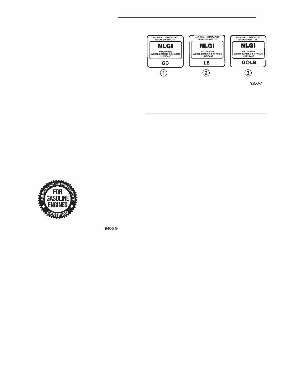
• National Lubricating Grease Institute (NLGI) (Fig. 3) ENGINE OIL SAE VISCOSITY RATING INDICATES ENGINE OIL VISCOSITY An SAE viscosity grade is used to specify the vis- cosity of engine oil. SAE 30 specifies a single viscos- ity engine oil. Engine oils also have multiple viscosities. These are specified with a dual SAE vis- cosity grade which indicates the cold-to-hot tempera- ture viscosity range. • SAE 30 = single grade engine oil. • SAE 10W-30 = multiple grade engine oil. DaimlerChrysler Corporation only recommends multiple grade engine oils. API QUALITY CLASSIFICATION This symbol (Fig. 2) on the front of an oil container means that the oil has been certified by the Ameri- can Petroleum Institute (API) to meet all the lubri- cation requirements specified by DailmlerChrysler Corporation. Refer to Group 9, Engine for gasoline engine oil specification. GEAR LUBRICANTS SAE ratings also apply to multiple grade gear lubricants. In addition, API classification defines the lubricants usage. LUBRICANTS AND GREASES Lubricating grease is rated for quality and usage by the NLGI. All approved products have the NLGI symbol (Fig. 3) on the label. At the bottom NLGI symbol is the usage and quality identification letters. Wheel bearing lubricant is identified by the letter “G”. Chassis lubricant is identified by the latter “L”. The letter following the usage letter indicates the quality of the lubricant. The following symbols indi- cate the highest quality. SPECIALIZED LUBRICANTS AND OILS Some maintenance or repair procedures may require the use of specialized lubricants or oils. Con- sult the appropriate sections in this manual for the correct application of these lubricants. FLUID CAPACITIES Fuel Tank Standard ...................... 57 L (15 gal.) Optional ....................... 83 L (22 gal.) Engine Oil W/Filter change 2.5L ......................... 4.3 L (4.5 qts.) 3.9L ......................... 4.3 L (4.5 qts.) 4.7L .......................... 5.7L (6.0 qts.) 5.9L ......................... 4.7 L (5.0 qts.) Cooling System 2.5L ......................... 9.3 L (9.8 qts.) 3.9L ....................... 13.2 L (14.0 qts.) 4.7L ....................... 16.0 L (17.0 qts.) 5.9L ....................... 13.5 L (14.3 qts.) Automatic Transmission Dry fill capacity. * 42RE ................... 9.1-9.5 L (19–20 pts.) 45RFE ..................... 13.33 L (28.0pts.) 46RE .................... 9.1-9.5 L (19–20pts.) * Depending on type and size of internal cooler, length and inside diameter of cooler lines, or use of an auxiliary cooler, these figures may vary. Refer to Group 21, Transmission for proper fluid fill proce- dure. Fig. 2 API Symbol Fig. 3 NLGI Symbol 1 – WHEEL BEARINGS 2 – CHASSIS LUBRICATION 3 – CHASSIS AND WHEEL BEARINGS 0-2 LUBRICATION AND MAINTENANCE AN SERVICE PROCEDURES (Continued)
Manual Transmission NV3500 ...................... 2.0 L (4.2 pts.) AX15 ........................ 3.1 L (6.6 pts.) *NV1500HD ................... 2.2 L (4.7pts.) * Include 0.1 L (0.22 pts.) Friction Modifier. Transfer Case NP231 ....................... 1.2 L (2.5 pts.) NP231–HD .................... 1.2 L (2.5 pts.) NP242 ....................... 1.2 L (2.5 pts.) Front Axle Model 194 .................... 1.4 L (3.0 pts.) Rear Axle 8-1/4 in ....................... 2.1 L (4.4 pts.) 9-1/4 in ....................... 2.3 L (4.8 pts.) Power Steering Power steering fluid capacities are dependent on engine/chassis options as well as steering gear/cooler options. Depending on type and size of internal cooler, length and inside diameter of cooler lines, or use of an auxiliary cooler, these capacities may vary. Refer to Section 19 of the service manual for proper fill and bleed procedures. AN LUBRICATION AND MAINTENANCE 0-3 SERVICE PROCEDURES (Continued)
MAINTENANCE SCHEDULES TABLE OF CONTENTS page SERVICE PROCEDURES MAINTENANCE SCHEDULES ................ 4 SERVICE PROCEDURES MAINTENANCE SCHEDULES There are two maintenance schedules that show proper service for the Dakota. First is Schedule “A”. It lists all the scheduled maintenance to be performed under “normal” operat- ing conditions. Second is Schedule “B”. It is a schedule for vehi- cles that are operated under the conditions listed at the beginning of that schedule. Use the schedule that best describes the driving conditions. Where time and mileage are listed, follow the interval that occurs first. At Each Stop For Gasoline • Check engine oil level, add as required. • Check windshield washer solvent and add if required. • Clean windshield and wiper blades as required. Once A Month • Check tire pressure and look for unusual wear or damage. • Inspect battery and clean and tighten terminals as required. • Check fluid levels of coolant reservoir, power steering and transmission and add as needed. • Check all lights and all other electrical items for correct operation. • Inspect and clean wiper blades. Replace if required. At Each Oil Change • Inspect exhaust system. • Inspect brake hoses. • Rotate the tires at each oil change interval shown on Schedule “A”: (7,500 miles) or every other interval shown on Schedule “B” (6,000 miles). • Check engine coolant level, hoses, and clamps. EMISSION CONTROL SYSTEM MAINTENANCE The scheduled emission maintenance listed in bold type on the Maintenance Schedules, must be done at the mileage specified to assure the continued proper functioning of the emission control system. These, and all other maintenance services included in this manual, should be done to provide the best vehicle performance and reliability. More frequent mainte- nance may be needed for vehicles in severe operating conditions such as dusty areas and very short trip driving. FLUID FILL LOCATIONS AND LUBRICATION POINTS The fluid fill/check locations and lubrication points are located in each applicable group. SCHEDULE “A” 7,500 Miles (12 000 km) or at 6 months • Change engine oil. • Replace engine oil filter. 15,000 Miles (24 000 km) or at 12 months • Change engine oil. • Replace engine oil filter. 22,500 Miles (36 000 km) or at 18 months • Change engine oil. • Replace engine oil filter. • Lubricate front suspension ball joints if required. • Inspect front wheel bearings. • Inspect brake linings. 30,000 Miles (48 000 km) or at 24 months • Change engine oil. • Replace engine oil filter. • Replace engine air cleaner element. • Replace spark plugs. • Drain and refill automatic transmission fluid and change filter (4.7L only). 0-4 LUBRICATION AND MAINTENANCE AN
37,500 Miles (60 000 km) or at 30 months • Change engine oil. • Replace engine oil filter. • Drain and refill transfer case fluid. • Drain and refill automatic transmission fluid. Replace filter and adjust bands (3.9L, and 5.9L only). 45,000 Miles (72 000 km) or at 36 months • Change engine oil. • Replace engine oil filter. • Lubricate front suspension ball joints if required. • Inspect front wheel bearings. • Inspect brake linings. • Flush and replace engine coolant at 36 months, regardless of mileage. 52,500 Miles (84 000 km) or at 42 months • Change engine oil. • Replace engine oil filter. • Flush and replace engine coolant if not done at 36 months. 60,000 Miles (96 000 km) or at 48 months • Change engine oil. • Replace engine oil filter. • Replace engine air cleaner element. • Replace ignition cables (2.5L, 3.9L, 5.9L). • Inspect PCV valve, replace as necessary. (3.9L, 4.7L, and 5.9L)* • Replace spark plugs. • Inspect auto tension drive belt and replace if required (3.9L, & 5.9L). • Inspect and adjust tension on drive belt (2.5L). • Drain and refill automatic transmission fluid and change filter (4.7L only). 67,500 Miles (108 000 km) or at 54 months • Change engine oil. • Replace engine oil filter. • Lubricate front suspension ball joints if required. • Inspect front wheel bearings. • Inspect brake linings. 75,000 Miles (120 000 km) or at 60 months • Change engine oil. • Replace engine oil filter. • Drain and refill automatic transmission fluid. Replace filter and adjust bands (3.9L & 5.9L). • Drain and refill transfer case. • Flush and replace engine coolant if it has been 30,000 miles (48 000 km) or 24 months since last change. • Inspect auto tension drive belt and replace if required (3.9L, & 5.9L). 82,500 Miles (132 000 km) or at 66 months • Change engine oil. • Replace engine oil filter. • Flush and replace engine coolant if it has been 30,000 miles (48 000 km) or 24 months since last change. 90,000 Miles (144 000 km) or at 72 months • Change engine oil. • Replace engine oil filter. • Replace engine air cleaner element. • Inspect PCV valve, replace as necessary. (3.9L, 4.7L, and 5.9L)* • Replace spark plugs. • Lubricate front suspension ball joints if required. • Inspect front wheel bearings. • Inspect brake linings. • Inspect auto tension drive belt and replace if required (3.9L, 4.7L, & 5.9L).D 97,500 Miles (156 000 km) or at 78 months • Change engine oil. • Replace engine oil filter. 105,000 Miles (168 000 km) or at 84 months • Change engine oil. • Replace engine oil filter. • Flush and replace engine coolant if it has been 30,000 Miles (48 000km) or 24 months since last change. • Inspect auto tension drive belt and replace if required (3.9L, 4.7L, & 5.9L).D 112,500 Miles (181 000 km) or at 90 months • Change engine oil. • Replace engine oil filter. • Drain and refill automatic transmission fluid. Replace filter and adjust bands (3.9L & 5.9L only). • Drain and refill transfer case fluid. • Lubricate front suspension ball joints if required. • Inspect front wheel bearings. • Inspect brake linings. • Flush and replace engine coolant if it has been 30,000 Miles (48 000km) or 24 months since last change. 120,000 Miles (192 000 km) or at 96 months • Change engine oil. • Replace engine oil filter. • Replace engine air cleaner element. • Replace ignition cables (2.5L, 3.9L & 5.9L). • Inspect PCV valve, replace as necessary. (3.9L, 4.7L, and 5.9L)* • Replace spark plugs. AN LUBRICATION AND MAINTENANCE 0-5 SERVICE PROCEDURES (Continued)
Fixing problems in your vehicle is a do-it-approach with the Auto Repair Manuals. These manuals contain comprehensive instructions and procedures on how to fix the problems in your ride. They are useful for both professional mechanics and DIY enthusiasts. The durability of your vehicle is unquestionable, but you also know that no matter how tough they are, constant use can cause them to deteriorate. When this happens, and ultimately it will, you will have to replace them. Some car parts are very simple to mount and do not require professional help. By having a trusty repair manual, you not only save money but you also get to experience the fun of do-it-yourself projects. A repair manual comes with comprehensive details regarding technical data, diagrams, a complete list of car parts, and pictures. Even the most novice car mechanic can easily follow the step-by-step guides which are made simple by the illustrations and drawings. You can find a complete list of accessories that can further enhance the performance of your engine.
The information contained in these repair manuals is the same as the ones used by the engineers of the company. These manuals cover all models and all repairs A-Z. They are not generic repair information; they are vehicle specific. The manuals include complete step-by-step instructions, diagrams, illustrations, wiring schematics, and specifications to completely repair your vehicle with ease. You get everything you will ever need in one easy-to-use manual. No more flipping through books to find what you need. Print only the pages and diagrams you require. No more greasy pages or torn lost paper manuals again. All pages are printable, so print off what you need and take it with you to your vehicle or workshop. You can blow-up images and then print off enlarged copies. These factory highly detailed repair manuals come with complete instructions and illustrations, wiring schematics, and diagrams to completely service and repair your vehicle. They are compatible with all versions of Windows and Mac. The language used is English, and they are printable. The requirements are Adobe Reader and Win, which are free online.
Auto Repair Manuals can save you a lot of time. These packages are complete with all your car information needs. You will surely enjoy browsing through the pages and learning how to repair the different parts of your car. It makes you up-to-date and more knowledgeable. Now, you don't have to rely on your mechanic for the simplest car repair. You can do it at the comfort of your garage. It's a fun activity that allows you to enter the realm of your car. All pages are printable, so print off what you need and take it with you into the garage or workshop. This manual will never get dirty and rip as you can keep it safely on your PC and print the pages you need in a matter of seconds.
Maintenance
Engine
Control System
Mechanical
Fuel Service Specifications
Emission Control
Intake Exhaust Cooling
Lube
Ignition Starting Charging
Auto Transmission Clutch
Manual Transmission
Transfer Propeller Shaft
Drive Shaft
Differential
Axle Suspension
Tire & Wheel
Brake Control
Brake
Parking Brake
Steering Column
Power Steering
Air Condition
Suppl Restraint System
Seat Belt
Engine Immobilizer
Cruise Control
Wiper & Washer
Door Lock
Meter Audio/Visual
Horn
Windshield/Glass Mirror
Instrument Panel
Seat
Engine Hood/ Door
Exterior & Interior
Electrical
Multiplex/ Can Communication
And much more...
These manuals are compatible with all versions of Windows and Mac. They are printable and available in English. The requirements are Adobe Reader and Win, which are free online.