

2001 Dodge Dakota Service Repair Manual 01
What's Included?
Fast Download Speeds
Offline Viewing
Access Contents & Bookmarks
Full Search Facility
Print one or all pages of your manual
GROUP TAB LOCATOR
Introduction
0
Lubrication & Maintenance
2
Suspension
3
Differential & Driveline
5
Brakes
6
Clutch
7
Cooling
8A
Audio
8B
Chime/Buzzer
8E
Electronic Control Modules
8F
Engine Systems
8G
Heated Systems
8H
Horn
8I
Ignition Control
8J
Instrument Cluster
8L
Lamps
8M
Message Systems
8N
Power Systems
8O
Restraints
8P
Speed Control
8Q
Vehicle Theft Security
8R
Wipers/Washers
8W
Wiring
9
Engine
11
Exhaust System
13
Frame & Bumpers
14
Fuel System
19
Steering
21
Transmission and Transfer Case
22
Tires/Wheels
23
Body
24
Heating & Air Conditioning
25
Emissions Control
30
New Vehicle Preparation
Component and System Index
Service Manual Comment Forms (Rear of Manual)
INTRODUCTION
TABLE OF CONTENTS
page page
VEHICLE SAFETY CERTIFICATION LABEL
DESCRIPTION ............................ 1
VEHICLE IDENTIFICATION NUMBER
DESCRIPTION ............................ 2
VECI LABEL
DESCRIPTION ............................ 3
BODY CODE PLATE
DESCRIPTION ............................ 3
EQUIPMENT IDENTIFICATION PLATE
DESCRIPTION ............................ 4
INTERNATIONAL SYMBOLS
DESCRIPTION ............................ 4
FASTENER IDENTIFICATION
DESCRIPTION ............................ 5
FASTENER USAGE
DESCRIPTION ............................ 5
METRIC SYSTEM
DESCRIPTION ............................ 8
TORQUE REFERENCES
DESCRIPTION ........................... 10
VEHICLE SAFETY
CERTIFICATION LABEL
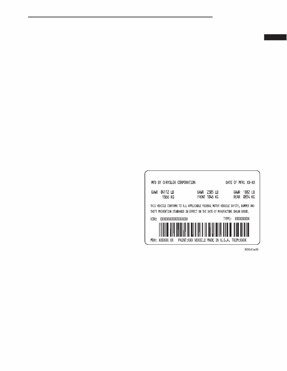
DESCRIPTION
A vehicle safety certification label is attached to
every DaimlerChrysler Corporation vehicle. The label
certifies that the vehicle conforms to all applicable
Federal Motor Vehicle Safety Standards. The label
also lists:
• Month and year of vehicle manufacture.
• Gross Vehicle Weight Rating (GVWR). The gross
front and rear axle weight ratings (GAWR’s) are
based on a minimum rim size and maximum cold tire
inflation pressure.
• Vehicle Identification Number (VIN).
• Type of vehicle.
• Type of rear wheels.
• Bar code.
• Month, Day and Hour (MDH) of final assembly.
• Paint and Trim codes.
• Country of origin.
The label is located on the driver-side door shut-
face (Fig. 1).
All communications or inquiries regarding the
vehicle should include the Month-Day-Hour and
Vehicle Identification Number.
Fig. 1 Vehicle Safety Certification Label
AN INTRODUCTION 1
VEHICLE IDENTIFICATION
NUMBER
DESCRIPTION
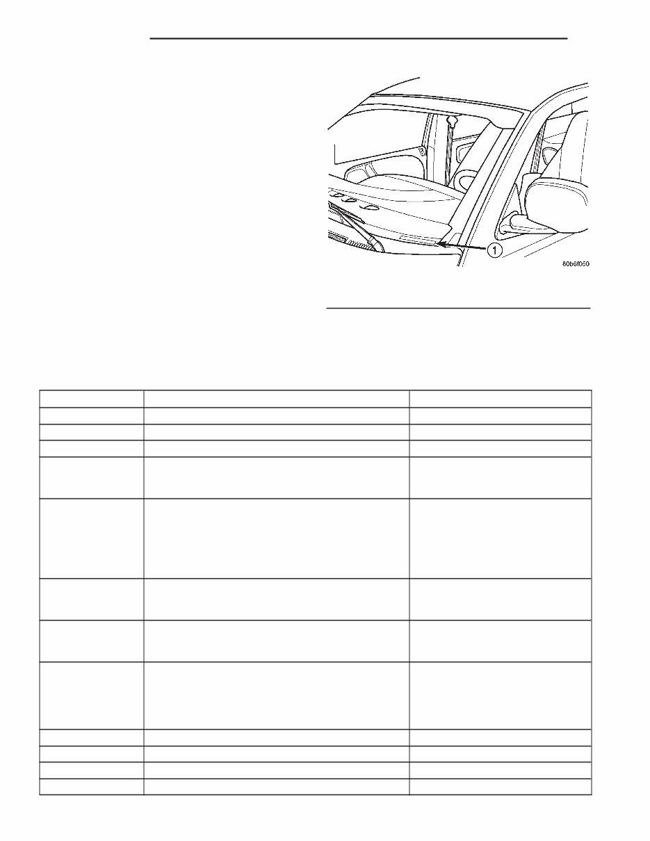
The Vehicle Identification Number (VIN) plate is
attached to the top left side of the instrument panel
(Fig. 2). The VIN contains 17 characters that provide
data concerning the vehicle. Refer to the decoding
chart to determine the identification of a vehicle.
VIN DECODING INFORMATION
POSITION INTERPRETATION CODE = DESCRIPTION
1 Country of Origin 1= USA
2 Make B = Dodge
3 Vehicle Type 7 = Truck
4 Gross Vehicle Weight Rating
F = 4001-5000 lbs.
G = 5001-6000 lbs.
H = 6001-7000 lbs.
5 Vehicle Line
G = Dakota
Dakota Sport
Dakota 4x4
L = Dakota
Dakota Sport
Dakota 4x2
6 Series
2 = Dakota
Dakota Sport
Dakota SLT
7 Body Style
2 = Club Cab
A = Quad Cab
6 = Conventional Cab
8 Engine
P = 2.5L
X = 3.9L
N=4.7L
Y = 5.2L
Z = 5.9L
9 Check Digit
10 Model Year 1=2001
11 Assembly Plant S = Warren Truck Assembly
12 Thru 17 Vehicle Build Sequence Assembly Sequence
Fig. 2 Vehicle Identification Number (VIN)
1 - VIN
2 INTRODUCTION AN
VECI LABEL
DESCRIPTION
All vehicles are equipped with a combined VECI
label. This label is located in the engine compart-
ment (Fig. 3).
The VECI label contains the following:
• Engine family and displacement
• Evaporative family
• Emission control system schematic
• Certification application
• Engine timing specifications (if adjustable)
• Idle speeds (if adjustable)
• Spark plug and gap
The label also contains an engine vacuum sche-
matic. There are unique labels for vehicles built for
sale in the state of California and the country of
Canada. Canadian labels are written in both the
English and French languages. These labels are per-
manently attached and cannot be removed without
defacing information and destroying label.
BODY CODE PLATE
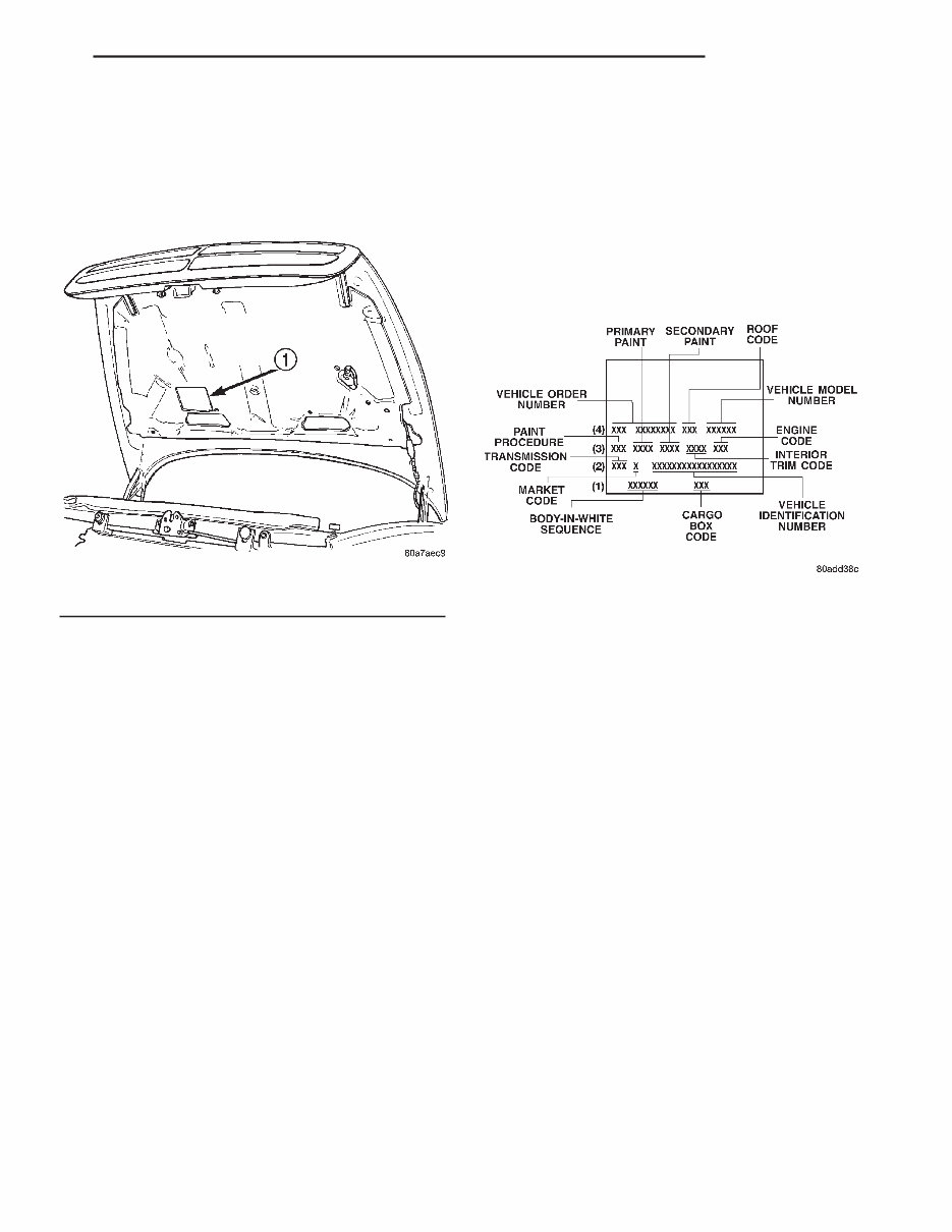
DESCRIPTION
LOCATION AND DECODING
A metal body code plate is attached to the floor pan
under the passenger seat. Remove the passenger
seat, door sill scuff plate and pull back the carpet to
access the body code plate. There are seven lines of
information on the body code plate. Lines 5, 6, and 7
are not used to define service information. Informa-
tion reads from left to right, starting with line 4 in
the center of the plate to line 1 at the bottom of the
plate (Fig. 4).
The last code imprinted on a vehicle code plate will
be followed by the imprinted word END. When two
vehicle code plates are required, the last available
spaces on the first plate will be imprinted with the
letters CTD (for continued).
When a second vehicle code plate is necessary, the
first four spaces on each row will not be used because
of the plate overlap.
BODY CODE PLATE—LINE 4
DIGITS 1 THROUGH 12
Vehicle Order Number
DIGITS 13, 14, AND 15
Open Space
DIGITS 16, 17, AND 18
Car Line Shell
• AN1 = Dakota 4 X 2
• AN5 = Dakota 4 X 4
DIGIT 19
Price Class
• L = Dakota (All)
DIGITS 20 AND 21
Body Type
• 31 = Dakota Club Cab (130.9 in. Wheel Base)
• 61 = Dakota (111.9 in. Wheel Base)
• 62 = Dakota (123.9 in. Wheel Base)
BODY CODE PLATE—LINE 3
DIGITS 1,2, AND 3
Paint Procedure
Fig. 3 VECI Label Location
1 - VEHICLE EMISSION CONTROL INFORMATION (VECI) LABEL
Fig. 4 Body Code
AN INTRODUCTION 3
DIGIT 4
Open Space
DIGITS 5 THROUGH 8
Primary Paint
Refer to Group 23, Body for color codes.
DIGIT 9
Open Space
DIGITS 10 THROUGH 13
Secondary Paint
DIGIT 14
Open Space
DIGITS 15 THROUGH 18
Interior Trim Code
DIGIT 19
Open Space
DIGITS 20, 21, AND 22
Engine Code
• EPE = 2.5 L 4 cyl. MPI Gasoline
• EHC = 3.9 L 6 cyl. MPI Gasoline
• ELF = 5.2 L 8 cyl. MPI Gasoline
• ELM = 5.9 L 8 cyl. MPI Gasoline
BODY CODE PLATE—LINE 2
DIGITS 1, 2, AND 3
Transmission Codes
• DDK = 5–Speed Manual (NVG 1500)
• DDQ = 5–Speed Manual (AX15)
• DDC = 5–Speed Manual (NVG 3500)
• DGK = 4–Speed Automatic (42RE)
• DGW = 4–Speed Automatic (44RE)
• DGT = 4–Speed Automatic (46RE)
DIGIT 4
Open Space
DIGIT 5
Market Code
• B = International
• C = Canada
• M = Mexico
• U = United States
DIGIT 6
Open Space
DIGITS 7 THROUGH 23
Vehicle Identification Number (VIN)
Refer to Vehicle Identification Number (VIN) para-
graph for proper breakdown of VIN code.
BODY CODE PLATE—LINE 1
DIGITS 1 THROUGH 6 Body-in-white assembly sequence.
DIGITS 7 THROUGH 9
Open Space
DIGITS 10 THROUGH 12 Cargo box code
• XBS = Sweptline
DIGITS 13 THROUGH 16
Open Space
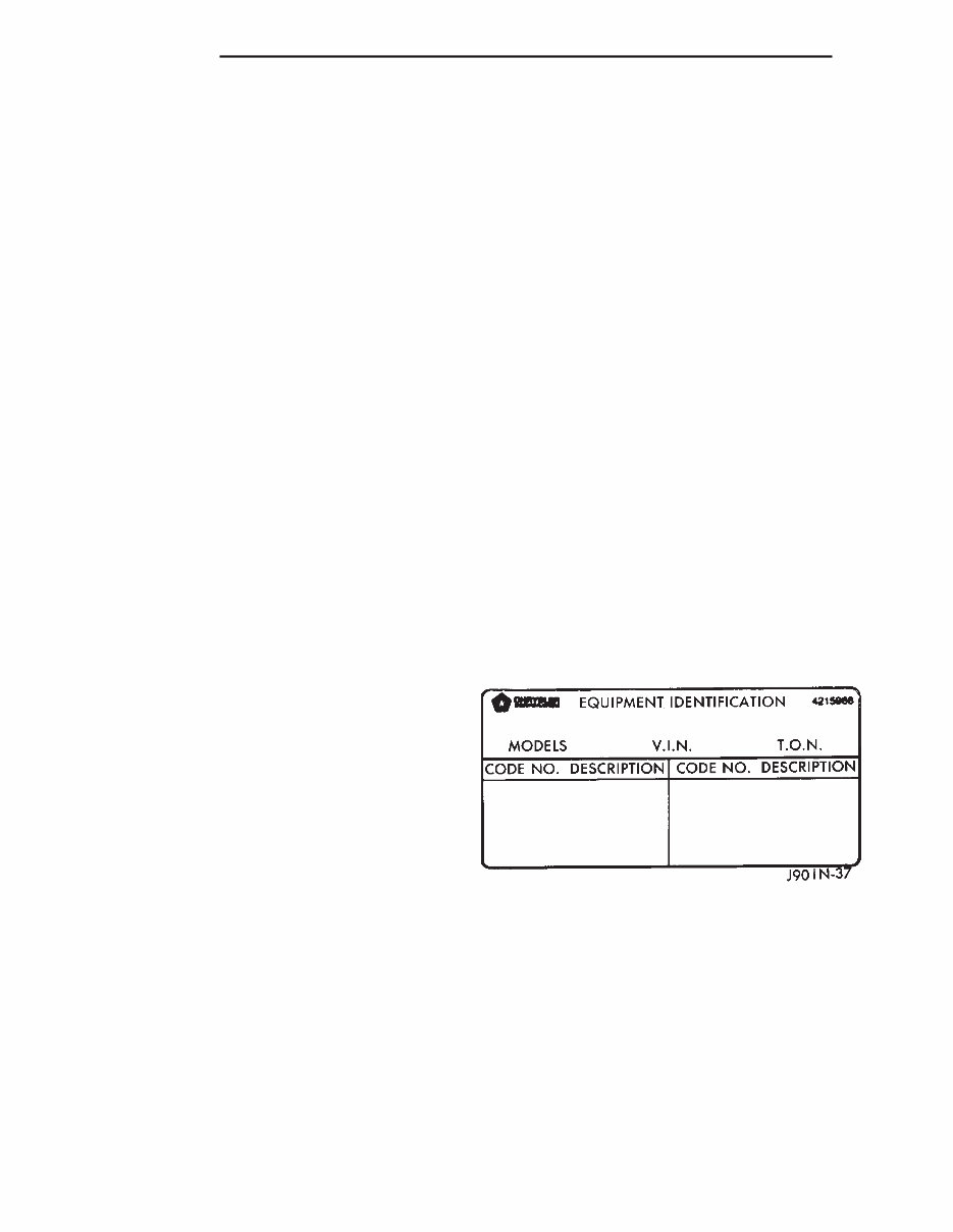
EQUIPMENT IDENTIFICATION
PLATE
DESCRIPTION
The Equipment Identification Plate (Fig. 5) is
located at the left, front of the inner hood panel. The
plate lists information concerning the vehicle as fol-
lows:
• The model.
• The wheelbase.
• The VIN (Vehicle Identification Number).
• The T.O.N. (order number).
• The optional and special equipment installed on
the vehicle.
Refer to the information listed on the plate when
ordering replacement parts.
INTERNATIONAL SYMBOLS
DESCRIPTION
The graphic symbols illustrated in the following
International Control and Display Symbols Chart
(Fig. 6) are used to identify various instrument con-
trols. The symbols correspond to the controls and dis-
plays that are located on the instrument panel.
Fig. 5 Equipment Identification Plate—Typical
4 INTRODUCTION AN
BODY CODE PLATE (Continued)
You're Reading a Preview
What's Included?
Fast Download Speeds
Offline Viewing
Access Contents & Bookmarks
Full Search Facility
Print one or all pages of your manual
$30.99
$40.99
Viewed 33 Times Today


Secure transaction
What's Included?
Fast Download Speeds
Offline Viewing
Access Contents & Bookmarks
Full Search Facility
Print one or all pages of your manual
$30.99
$40.99
This Service Repair Manual for the 2001 Dodge Dakota is a comprehensive guide containing high-quality diagrams and instructions for servicing and repairing every aspect of the vehicle. It covers a wide range of topics including:
- Introduction
- Lubrication & Maintenance
- Suspension
- Differential & Driveline
- Brakes
- Clutch
- Cooling
- Audio
- Chime/Buzzer
- Electronic Control Modules
- Engine Systems
- Heated Systems
- Horn
- Ignition Control
- Instrument Cluster
- Lamps
- Message Systems
- Power Systems
- Restraints
- Speed Control
- Vehicle Theft Security
- Wipers/Washers
- Wiring
- Engine
- Exhaust System
- Frame & Bumpers
- Fuel System
- Steering
- Transmission and Transfer Case
- Tires/Wheels
- Body
- Heating & Air Conditioning
- Emissions Control
- New Vehicle Preparation
- Component and System Index
This manual is essential for both professional mechanics and DIY enthusiasts. It is available in a printable file format, compatible with all versions of Windows and Mac, and can be viewed using Adobe Reader. With instant access, this manual is a cost-effective solution for maintaining and repairing your 2001 Dodge Dakota.


