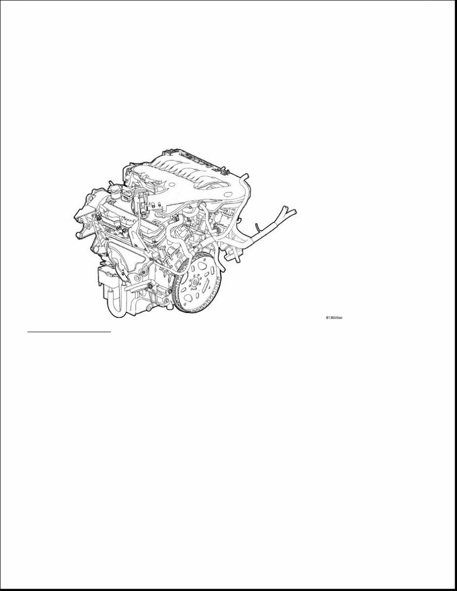
ENGINE 3.5L - Service Information - Challenger DESCRIPTION 3.5L Fig. 1: 3.5L ENGINE Courtesy of CHRYSLER LLC The 3.5 Liter (214 Cubic Inches) 60°V-6 engine is a single overhead camshaft design with hydraulic lifters and four valves per cylinder. The engine does not have provisions for a free wheeling valve train.
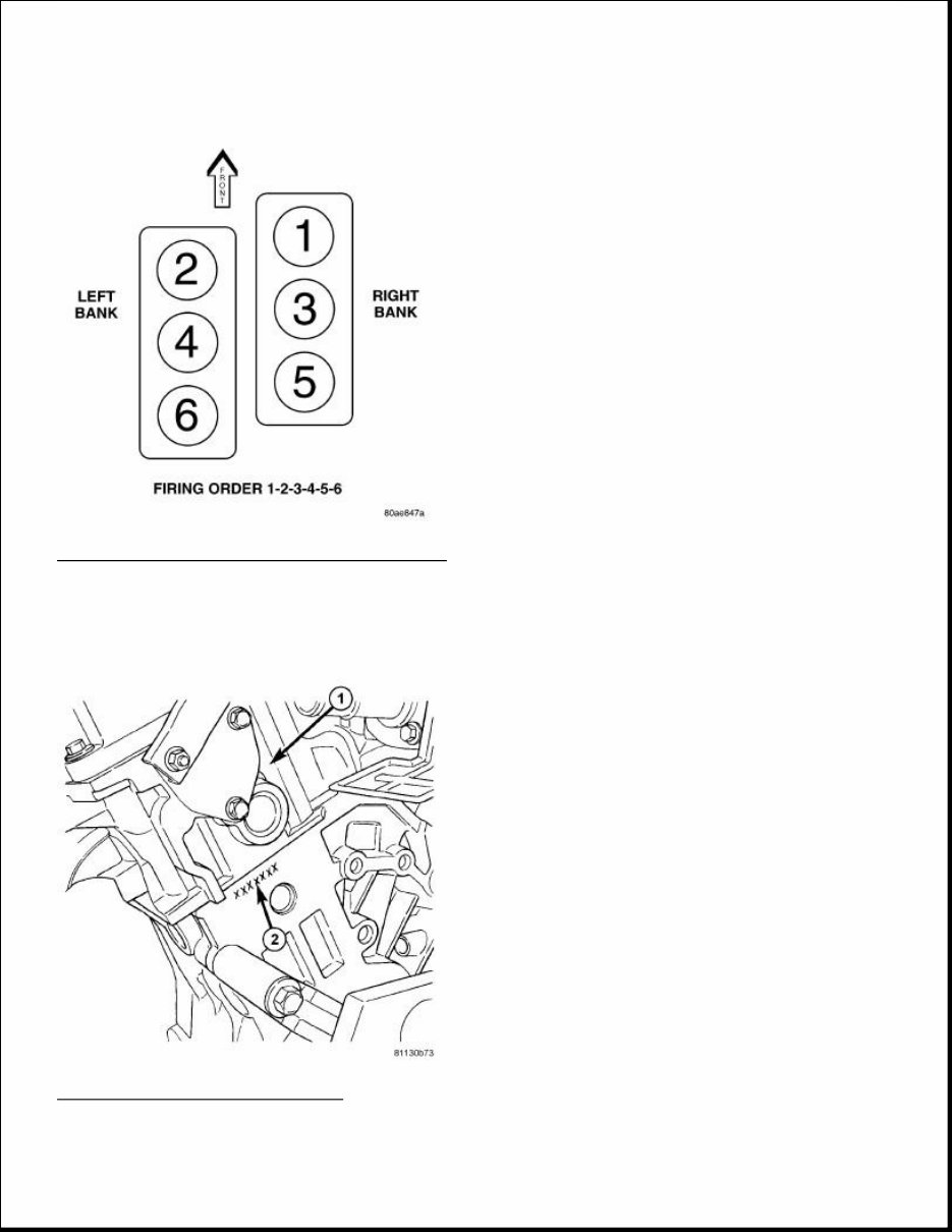
Fig. 2: Cylinder Numbering and Firing Order Courtesy of CHRYSLER LLC The cylinders are numbered from front to rear, with the right bank odd numbered, and the left bank even numbered. The firing order is 1-2-3-4-5-6. Fig. 3: ENGINE IDENTIFICATION Courtesy of CHRYSLER LLC
The engine identification number (2) is located on the rear of engine block just below the left cylinder head (1). DIAGNOSIS AND TESTING INTRODUCTION Engine diagnosis is helpful in determining the causes of malfunctions not detected and remedied by routine maintenance. These malfunctions may be classified as either mechanical (e.g., a strange noise), or performance (e.g., engine idles rough and stalls). See ENGINE PERFORMANCE and ENGINE MECHANICAL for possible causes and corrections of malfunctions. Refer to FUEL SYSTEM for the fuel system diagnosis. Additional tests and diagnostic procedures may be necessary for specific engine malfunctions that cannot be isolated with the Service Diagnosis charts. Information concerning additional tests and diagnosis is provided within the following: Cylinder Compression Pressure Test: Refer to CYLINDER COMPRESSION PRESSURE TEST . Cylinder Combustion Pressure Leakage Test: Refer to CYLINDER COMBUSTION PRESSURE LEAKAGE TEST . Cylinder Head Gasket Failure Diagnosis: Refer to CYLINDER HEAD GASKET . Intake Manifold Leakage Diagnosis: Refer to MANIFOLD, Intake . Lash Adjuster (Tappet) Noise Diagnosis: Refer to LASH ADJUSTER (TAPPET) NOISE DIAGNOSIS . Engine Oil Leak Inspection: Refer to ENGINE OIL LEAK INSPECTION . ENGINE PERFORMANCE 1 - REAR OF LEFT CYLINDER HEAD 2 - ENGINE IDENTIFICATION NUMBER CONDITION POSSIBLE CAUSE CORRECTION ENGINE WILL NOT START 1. Weak battery. 1. Test battery. Charge or replace as necessary. Refer to Electrical/Battery System/BATTERY - Description . 2. Corroded or loose battery connections. 2. Clean and tighten battery connections. Apply a coat of light mineral grease to terminals. 3. Faulty starter. 3. Test starting system. Refer to
Electrical/Starting - Diagnosis and Testing . 4. Faulty coil(s) or control unit. 4. Test and replace as needed. (Refer to Appropriate Diagnostic Information) 5. Incorrect spark plug gap. 5. Check and adjust gap as needed. 6. Contamination in fuel system. 6. Clean system and replace fuel filter. 7. Faulty fuel pump. 7. Test fuel pump and replace as needed. (Refer to Appropriate Diagnostic Information) 8. Incorrect engine timing. 8. Check for a skipped timing belt or a loose camshaft sprocket. ENGINE STALLS OR IDLES ROUGH 1. Idle speed too low. 1. Test minimum air flow. (Refer to Appropriate Diagnostic Information) 2. Incorrect fuel mixture. 2. (Refer to Appropriate Diagnostic Information) 3. Intake manifold leakage. 3. Inspect intake manifold gasket, manifold, and vacuum hoses. 4. Faulty coil(s). 4. Test and replace as necessary. (Refer to Appropriate Diagnostic Information) ENGINE LOSS OF POWER 1. Dirty or incorrectly gapped plugs. 1. Set gap as needed or replace plug(s). 2. Contamination in fuel system. 2. Clean system and replace fuel filter. 3. Faulty fuel pump. 3. Test and replace as necessary. (Refer to Appropriate Diagnostic Information) 4. Incorrect valve timing. 4. Correct valve timing as needed. 5. Leaking cylinder head gasket. 5. Replace cylinder head gasket. 6. Low compression. 6. Test compression of each cylinder. 7. Burned, warped, or pitted valves. 7. Replace valves. 8. Plugged or restricted exhaust system. 8. Check exhaust system restriction. Replace parts, as
ENGINE MECHANICAL necessary. 9. Faulty coil(s). 9. Test and replace as necessary. (Refer to Appropriate Diagnostic Information) ENGINE MISSES ON ACCELERATION 1. Dirty or incorrectly gapped spark plugs. 1. Set gap as needed or replace plug(s). 2. Contamination in Fuel System. 2. Clean fuel system and replace fuel filter. 3. Burned, warped, or pitted valves. 3. Replace valves. 4. Faulty coil(s). 4. Test and replace as necessary. (Refer to Appropriate Diagnostic Information) ENGINE MISSES AT HIGH SPEED 1. Dirty or incorrect spark plug gap. 1. Set gap as needed or replace plug(s). 2. Faulty coil(s). 2. Test and replace as necessary. (Refer to Appropriate Diagnostic Information) 3. Dirty fuel injector(s). 3. Test and replace as necessary. (Refer to Appropriate Diagnostic Information) 4. Contamination in fuel system. 4. Clean system and replace fuel filter. CONDITION POSSIBLE CAUSES CORRECTION NOISY VALVES 1. High or low oil level in crankcase. 1. Check and correct engine oil level. 2. Thin or diluted oil. 2. Change oil to correct viscosity. 3. Thick oil 3. (a.) Change oil and filter. (b.) Run engine to operating temperature. (c.) Change oil and filter again. 4. Low oil pressure. 4. Check and correct engine oil level. 5. Dirt in tappets/lash adjusters. 5. Replace rocker arm/hydraulic lash adjuster assembly. 6. Worn rocker arms. 6. Inspect oil supply to rocker
arms. 7. Worn tappets/lash adjusters. 7. Install new rocker arm/hydraulic lash adjuster assembly. 8. Worn valve guides. 8. Replace cylinder head(s). 9. Excessive runout of valve seats on valve faces. 9. Grind valve seats and valves. 10. Missing adjuster pivot. 10. Replace rocker arm/hydraulic lash adjuster assembly. CONNECTING ROD NOISE 1. Insufficient oil supply. 1. Check engine oil level. 2. Low oil pressure. 2. Check engine oil level. Inspect oil pump relief valve and spring. 3. Thick/Thin or diluted oil. 3. Change oil to correct viscosity. - 3. (a.) Change oil and filter. (b.) Run engine to operating temperature. (c.) Change oil and filter again. 4. Excessive bearing clearance. 4. Measure bearings for correct clearance. Repair as necessary. 5. Connecting rod journal out- of-round. 5. Replace crankshaft or grind surface. 6. Misaligned connecting rods. 6. Replace bent connecting rods. MAIN BEARING NOISE 1. Insufficient oil supply. 1. Check engine oil level. 2. Low oil pressure. 2. Check engine oil level. Inspect oil pump relief valve and spring. 3. Thick/Thin or diluted oil. 3. Change oil to correct viscosity. - 3. (a.) Change oil and filter. (b.) Run engine to operating temperature. (c.) Change oil and filter again. 4. Excessive bearing clearance. 4. Measure bearings for correct clearance. Repair as necessary. 5. Excessive end play. 5. Check thrust bearing for wear on flanges. 6. Crankshaft journal out-of- round or worn. 6. Replace crankshaft or grind journals. 7. Loose flywheel or torque 7. Tighten to correct torque.
CYLINDER COMPRESSION PRESSURE TEST The results of a cylinder compression pressure test can be utilized to diagnose several engine malfunctions. converter. OIL PRESSURE DROP 1. Low oil level. 1. Check engine oil level. 2. Faulty oil pressure sending unit. 2. Install new sending unit. 3. Low oil pressure. 3. Check sending unit and main bearing oil clearance. 4. Clogged oil filter. 4. Install new oil filter. 5. Worn parts in oil pump. 5. Replace worn parts or pump. 6. Thin or diluted oil. 6. Change oil to correct viscosity. 7. Oil pump relief valve stuck. 7. Remove valve and inspect, clean, or replace. 8. Oil pump suction tube loose. 8. Remove oil pan and install new tube or clean, if necessary. 9. Oil pump cover warped or cracked. 9. Install new oil pump. 10. Excessive bearing clearance. 10. Measure bearings for correct clearance. OIL LEAKS 1. Misaligned or deteriorated gaskets. 1. Replace gasket(s). 2. Loose fastener, broken or porous metal part. 2. Tighten, repair or replace the part. 3. Misaligned or deteriorated cup or threaded plug. 3. Replace as necessary. OIL CONSUMPTION OR SPARK PLUGS FOULED 1. PCV system malfunction. 1. Check system and repair as necessary. (Refer to Appropriate Diagnostic Information) 2. Worn, scuffed or broken rings. 2. Hone cylinder bores. Install new rings. 3. Carbon in oil ring slots. 3. Clean pistons and install new rings. 4. Rings fitted too tightly in grooves. 4. Remove rings and check grooves. If groove is not proper width, replace piston. 5. Worn valve guide(s). 5. Replace cylinder head(s). 6. Valve stem seal(s) worn or damaged. 6. Replace seal(s).
Ensure the battery is completely charged and the engine starter motor is in good operating condition. Otherwise the indicated compression pressures may not be valid for diagnosis purposes. 1. Check engine oil level and add oil if necessary. 2. Drive the vehicle until engine reaches normal operating temperature. Select a route free from traffic and other forms of congestion, observe all traffic laws, and accelerate through the gears several times briskly. 3. Remove all spark plugs from engine. As spark plugs are being removed, check electrodes for abnormal firing indicators such as fouled, hot, oily, etc. Record cylinder number of spark plug for future reference. 4. Remove the Auto Shutdown (ASD) relay from the TIPM. 5. Insert compression gauge adaptor Special Tool 8116 or the equivalent, into the #1 spark plug hole in cylinder head. Connect the 0-500 psi (Blue) pressure transducer (Special Tool CH7059) with cable adaptors to the scan tool. For Special Tool identification, see Engine - Special Tools . 6. Crank engine until maximum pressure is reached on gauge. Record this pressure as #1 cylinder pressure. 7. Repeat the previous step for all remaining cylinders. 8. Compression should not be less than 689 kPa (100 psi) and not vary more than 25 percent from cylinder to cylinder. 9. If one or more cylinders have abnormally low compression pressures, repeat the compression test. 10. If the same cylinder or cylinders repeat an abnormally low reading on the second compression test, it could indicate the existence of a problem in the cylinder in question. The recommended compression pressures are to be used only as a guide to diagnosing engine problems. An engine should not be disassembled to determine the cause of low compression unless some malfunction is present. CYLINDER COMBUSTION PRESSURE LEAKAGE TEST The combustion pressure leakage test provides an accurate means for determining engine condition. Combustion pressure leakage testing will detect: Exhaust and intake valve leaks (improper seating). Leaks between adjacent cylinders or into water jacket. Any causes for combustion/compression pressure loss. 1. Check the coolant level and fill as required. DO NOT install the pressure cap. 2. Start and operate the engine until it attains normal operating temperature, then turn the engine WARNING: DO NOT REMOVE THE PRESSURE CAP WITH THE SYSTEM HOT AND UNDER PRESSURE BECAUSE SERIOUS BURNS FROM COOLANT CAN OCCUR.
OFF. 3. Clean spark plug recesses with compressed air. 4. Remove the spark plugs. 5. Remove the oil filler cap. 6. Remove the air cleaner. 7. Calibrate the tester according to the manufacturer's instructions. The shop air source for testing should maintain 483 kPa (70 psi) minimum, 1,379 kPa (200 psi) maximum, with 552 kPa (80 psi) recommended. 8. Perform the test procedures on each cylinder according to the tester manufacturer's instructions. While testing, listen for pressurized air escaping through the throttle body, tailpipe and oil filler cap opening. Check for bubbles in the coolant. 9. All gauge pressure indications should be equal, with no more than 25% leakage per cylinder. 10. FOR EXAMPLE: At 552 kPa (80 psi) input pressure, a minimum of 414 kPa (60 psi) should be maintained in the cylinder. ENGINE OIL LEAK INSPECTION Begin with a thorough visual inspection of the engine, particularly at the area of the suspected leak. If an oil leak source is not readily identifiable, the following steps should be followed: 1. Do not clean or degrease the engine at this time because some solvents may cause rubber to swell, temporarily stopping the leak. 2. Add an oil soluble dye (use as recommended by manufacturer). Start the engine and let idle for approximately 15 minutes. Check the oil level indicator to make sure the dye is thoroughly mixed as indicated with a bright yellow color under a black light. 3. Using a black light, inspect the entire engine for fluorescent dye, particularly at the suspected area of oil leak. If the oil leak is found and identified, repair as necessary. 4. If dye is not observed, drive the vehicle at various speeds for approximately 24 km (15 miles), and repeat inspection. 5. If the oil leak source is not positively identified at this time , proceed with the AIR LEAK DETECTION TEST METHOD as follows: Disconnect the fresh air hose (make-up air) at the cylinder head cover and plug or cap the nipple on the cover. Remove the PCV valve hose from the cylinder head cover. Cap or plug the PCV valve nipple on the cover. Attach an air hose with pressure gauge and regulator to the oil level indicator tube. Gradually apply air pressure from 1 psi to 2.5 psi maximum while applying soapy water at the suspected source. Adjust the regulator to the suitable test pressure that provides the best bubbles which will pinpoint the leak source. If the oil leak is detected and identified, CAUTION: Do not subject the engine assembly to more than 20.6 kPa (3 PSI) of test pressure.
Get your hands on the 2013 Dodge Challenger Service & Repair Manual for all models. This manual provides comprehensive instructions and procedures to fix any issues with your vehicle. Whether you're a professional mechanic or a DIY enthusiast, these manuals can be invaluable for immediate car repairs. The manual includes technical data, diagrams, a complete list of car parts, and pictures, making it easy for even novice car mechanics to follow. It covers maintenance, engine, control system, mechanical, fuel service specifications, emission control, and much more. The repair manual is compatible with all versions of Windows and Mac, and it's printable, allowing you to take the necessary pages with you to your vehicle or workshop. With this manual, you can save time and money by learning to repair different parts of your car on your own. It's a valuable resource that keeps your car up-to-date and enhances your knowledge. Say goodbye to greasy and torn paper manuals, as this digital manual can be easily stored on your PC and printed whenever needed.
Complete step-by-step instructions, diagrams, illustrations, wiring schematics, and specifications
Factory highly detailed repair manuals with complete instructions and illustrations
Compatible with Windows Vista32 and 64, XP, ME, 98, NT, 2000, and Mac
Language: English
Requirements: Adobe Reader and Win
Don't rely solely on your mechanic for simple car repairs. With this manual, you can take charge of maintaining and repairing your vehicle, all while enjoying the fun of do-it-yourself projects. The manual is designed to be user-friendly, allowing you to print only the pages and diagrams you require. It's a valuable resource that keeps your car up-to-date and enhances your knowledge. Say goodbye to greasy and torn paper manuals, as this digital manual can be easily stored on your PC and printed whenever needed.