2008-2018 Dodge Challenger Service & Repair Manual
What's Included?
Lifetime Access
Fast Download Speeds
Online & Offline Access
Access PDF Contents & Bookmarks
Full Search Facility
Print one or all pages of your manual
2015-2016 Dodge Challenger
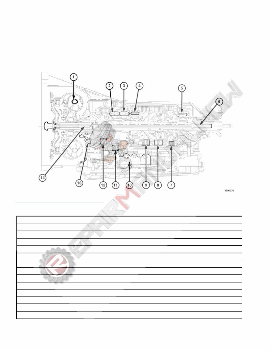
2015-16 AUTOMATIC TRANSMISSION 8HP70 - Service Information - Challenger DESCRIPTION DESCRIPTION Fig. 1: 8HP70 Automatic Transmission Courtesy of CHRYSLER GROUP, LLC 1 - TORQUE CONVERTER 2 -P1 PLANETARY 3 - P2 PLANETARY 4 - P3 PLANETARY 5 - P4 PLANETARY 6 - OUTPUT SHAFT 7 - D CLUTCH 8 - C CLUTCH 9 - E CLUTCH 10 - VALVE BODY 11 - B CLUTCH 12 - A CLUTCH 13 - OIL PUMP 14 - INPUT SHAFT CAUTION: A unique transmission fluid has been developed for this transmission. This
fluid is NOT compatible with ATF+4 or any other current Chrysler transmission fluid. For specifics about this unique fluid see VEHICLE QUICK REFERENCE . The transmission case is a single-piece unit. The starter pocket, cooler line fittings, and manual park release lever are located on the driver's side of the case. The electrical connector and oil fill plug are located on the passenger side of the case. The transmission uses a flanged output shaft connection. OPERATION OPERATION CAUTION: A unique transmission fluid has been developed for this transmission. This fluid is NOT compatible with ATF+4 or any other current Chrysler transmission fluid. For specifics about this unique fluid see VEHICLE QUICK REFERENCE . The 8HP70 is an electronic eight-speed automatic transmission. The Transmission Control Module Assembly (TCMA), which is integrated into the valve body, provides fully synchronized clutch-to-clutch shifting through four planetary gear sets. The TCMA includes a mounting plate that holds the Transmission Control Module (TCM) and a molded wiring harness for connection to various transmission sensors and solenoids. The valve body assembly contains all the sensors and solenoids required for operation, completely inside the transmission. Eight speeds allow the engine to maintain its optimal rpm range, increasing fuel economy and performance. Transmission control is performed by the TCM based on hard-wired and CAN bus signals from sensors and modules. The TCM receives driveability data from the Powertrain Control Module (PCM) and other modules over the CAN-C bus. It also receives shift lever position information from the electronic shifter over a dedicated transmission CAN bus. The TCM processes this input data and controls operation of the torque converter clutch, park lock system, solenoid valves, and pressure regulating valve. The input and output speed sensors are Hall-effect sensors that measure shaft rotational speed. The input speed sensor is located at the top, near the center, of the of the TCMA and reads input shaft speed from the magnetic ring on the P2 carrier. The output speed sensor is located at the back of the TCMA and reads output shaft speed from the P4 carrier FILTER SERVICE The 8HP70 has a conventional fluid sump design, however, the filter is integrated into the oil pan resulting in a lower profile for improved vehicle packaging. The oil pan gasket is reusable providing it is not damaged during removal. FLUID CHECK AND FILL A fluid fill tube and indicator are not provided. All work is performed under the vehicle while raised on a hoist. In the event of a transmission shift quality concern, a fluid leak, or in conjunction with a transmission repair, the transmission fluid level must be validated and topped off as necessary. The procedure involves the use of a scan tool to monitor transmission fluid temperature. Specific service procedures are necessary to check and fill the transmission with fluid. Refer to FLUID AND FILTER, STANDARD PROCEDURE. CLUTCHES The 8HP70 transmission uses two multi-plate holding clutches (A and B) and three multi-plate driving (rotating) clutches (C, D, and E). Gear shifts from one - eight and eight - one are synchronous shifts, meaning one of the clutches must continue to transmit torque at lower pressure until the other clutch is able to accept the 2 iš 212
input torque. Clutches A and B are holding clutches. Clutch A is applied by hydraulic pressure and released by a return spring, similar to the driving clutches. Clutch B operation is unique because it has fluid chambers on both sides of the apply piston, and therefore it is applied and released hydraulically. Regulation of fluid pressure on each side of the piston allows precise positioning of clutch B for apply, release, and controlled slip conditions. Clutches C, D, and E operate in a similar manner. Regulated pressure is available at the clutch C shift solenoid and the clutch valve. When the shift solenoid is de-energized, fluid flows through the shift solenoid and applies pressure to the clutch valve. During the shift, pressure moves the clutch valve, which begins to apply the clutch. Pressure from the holding valve regulates the opening of the clutch valve, softening the shift. Above a set threshold, the holding valve seats and allows the clutch valve to open completely. EMERGENCY RUNNING FUNCTION - LIMP IN MODE In the event of a complete transmission electrical failure (loss of power to the TCM), the transmission enters default limp-in mode. When the TCM loses power, all solenoids are de-energized. Maximum pressure locks the transmission in 6th gear, and a diagnostic trouble code (DTC) is stored in memory. If the vehicle is in a forward gear range when the fault occurs, the transmission defaults to 6th gear. If the vehicle is in park, reverse, or neutral, or if the engine is turned off when the fault occurs, the transmission will remain in park because the park lock release system cannot release the parking pawl. No hydraulic pressure is supplied to the driving clutches. In this situation, the manual park release lever must be used to disengage the park pawl. The limp-in function remains active until the DTC is rectified or the stored DTC is erased with the appropriate scan tool. OIL PUMP OPERATION The oil pump is located just behind the torque converter, between the pump housing and cover assemblies. The torque converter drives the pump assembly using a chain and sprockets. The oil pump is a double-stroke vane pump. The pump has dual chambers, two inlet and two outlet ports, allowing it to produce the fluid volume necessary for all operating conditions. The pump draws fluid through a filter and pressurizes the fluid as the pump rotates. After the fluid is pressurized, it exits the pump through two exhaust ports that feed the system pressure valve. The system pressure valve maintains fluid pressure and allows excess pressure to be returned to the pump. This reduces cavitation and noise. A slipping clutch can often be determined by comparing which internal units are applied in the various gear ranges. The Clutch Application chart provides a basis for analyzing road test results. SOLENOID APPLICATION GEAR PARK A B C D E TCC LPS P OFF ON TP OFF OFF OFF OFF OFF N ON ON TP OFF OFF OFF OFF OFF R ON ON ON OFF ON OFF OFF Ā± 1 ON ON ON ON OFF OFF Ā± Ā± 2 ON ON ON OFF OFF ON Ā± Ā± 3 ON OFF ON ON OFF ON Ā± Ā± 3 iš 212
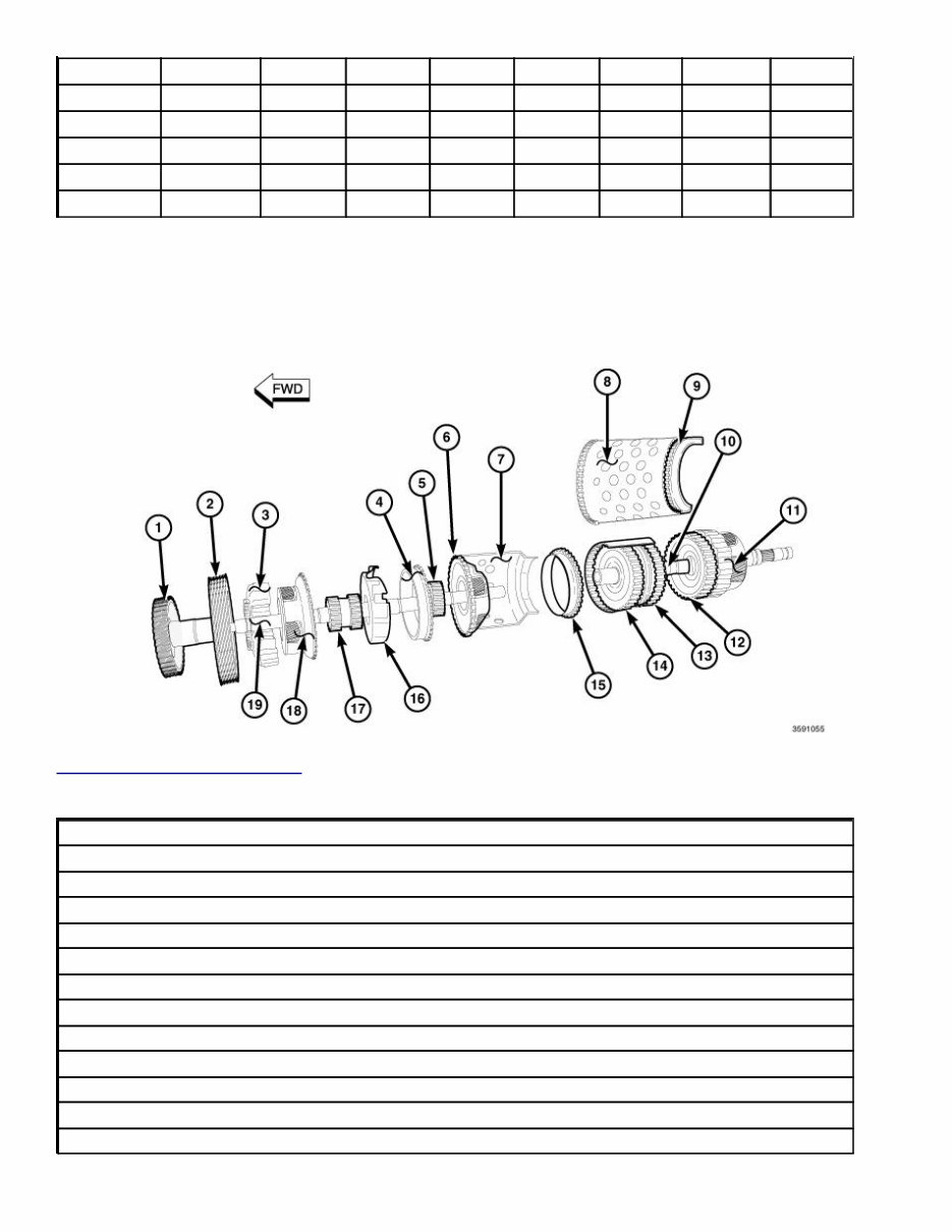
GEAR PARK A B C D E TCC LPS 4 ON OFF ON OFF ON ON Ā± Ā± 5 ON OFF ON ON ON OFF Ā± Ā± 6 ON OFF OFF ON ON ON Ā± Ā± 7 ON ON OFF ON ON OFF Ā± Ā± 8 ON ON OFF OFF ON ON Ā± Ā± TP= Touch Point Pressure Ā± = Variable Actuation POWERFLOW COMPONENTS Fig. 2: Powerflow Components Courtesy of CHRYSLER GROUP, LLC 1- A CLUTCH 2 - B CLUTCH 3 - P1 ANNULUS (PARTIAL CUTAWAY) 4 - P2 ANNULUS 5 - P3 SUN GEAR 6 - P3 CARRIER 7 - D CLUTCH DRUM (PARTIAL CUTAWAY) 8 - P4 ANNULUS DRUM (PARTIAL CUTAWAY) 9 - P4 ANNULUS (PARTIAL CUTAWAY) 10 - P4 SUN GEAR/D CLUTCH RETAINER (PARTIAL CUTAWAY) 11 - P4 CARRIER 12 - D CLUTCH 13 - C CLUTCH 4 iš 212
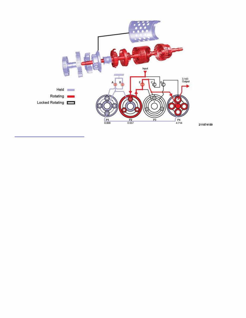
14 - E CLUTCH 15 - P3 ANNULUS 16 - P2 CARRIER 17 - P1/P2 SUN GEAR 18 - P1 CARRIER 19 - INPUT SHAFT Ā Use this POWER FLOW COMPONENTS graphic and chart to identify the individual components of the specific gear powerflow explanations below: Fig. 3: Powerflow In First Gear Courtesy of CHRYSLER GROUP, LLC FIRST GEAR POWERFLOW Clutch A (1) holds the P1/P2 sun gear (17) and clutch B (2) holds the P1 annulus (3). Because two members of the same gear set are held, the entire P1 gear set is stationary. The stationary P1 carrier (18) is connected to the P4 annulus (9), locking the annulus. The input shaft (19) drives the C clutch (13), and the C clutch (13) drives the P4 sun gear (10). The P4 sun gear (10) drives the P4 carrier (11), whose pinions walk around the held P4 annulus (9). 5 iš 212
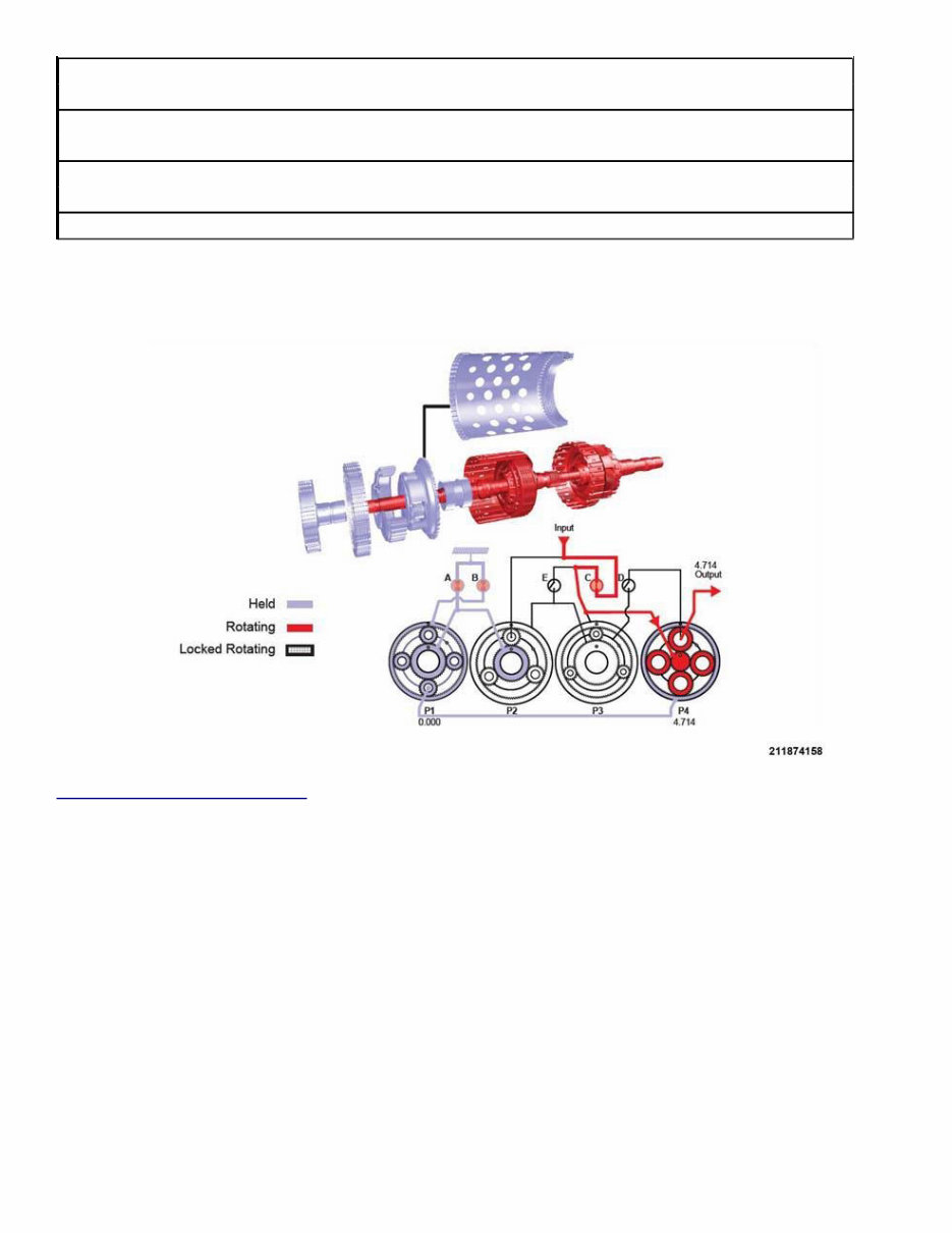
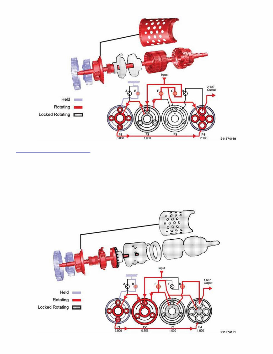
Fig. 4: Powerflow In Second Gear Courtesy of CHRYSLER GROUP, LLC SECOND GEAR POWERFLOW Clutch A (1) holds the P1/P2 sun gear (17) and clutch B (2) holds the P1 annulus (3). As with 1st gear, the entire P1 gear set is stationary. The stationary P1 carrier (18) is connected to the P4 annulus (9), locking the annulus. The input shaft (19) drives the P2 carrier (16). The P2 carrier (16) drives the P2 annulus (4). The P2 annulus (4) drives the E clutch (14) through the P3 sun gear (5) connection. The E clutch (14) then drives the P4 sun gear (10). The P4 sun gear (10) drives the P4 carrier (11), whose pinions walk around the held P4 annulus (9). 6 iš 212
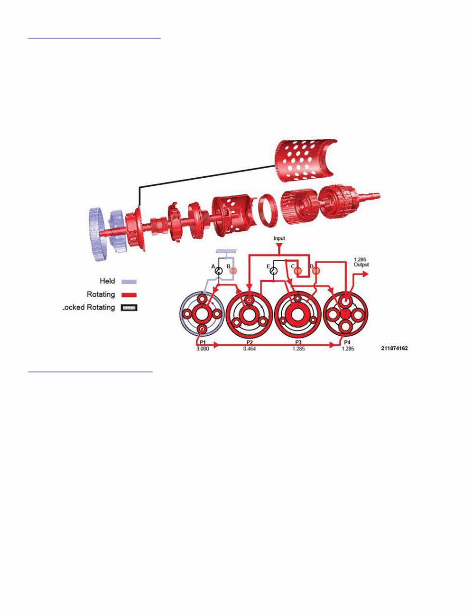
Fig. 5: Powerflow In Third Gear Courtesy of CHRYSLER GROUP, LLC THIRD GEAR POWERFLOW Clutch B (2) holds the P1 (3) annulus. The input shaft (19) drives the C clutch (12), which drives the P4 annulus (9). The C clutch (12) also drives the E clutch (14), which drives the P2 annulus (4). Because the P2 carrier (16) and the P2 annulus (4) are both driven at input shaft speed, the P2 gear set is locked at input shaft speed. The P1/P2 sun gear (17) drives the P1 carrier (18), and the P1 carrier drives the P4 annulus (9). 7 iš 212
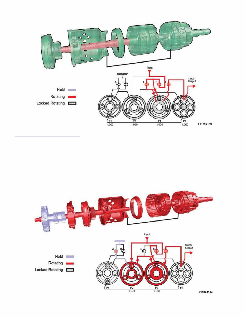
Fig. 6: Powerflow In Fourth Gear Courtesy of CHRYSLER GROUP, LLC FOURTH GEAR POWERFLOW Clutch B (2) holds the P1 annulus (3). With the E (14) and D (12) clutches applied, all components of the P3 and P4 gear sets are locked together to rotate at the same speed. The input shaft (19) drives the P2 carrier (16) which drives the P1/P2 sun gear (17). The P1/P2 sun gear drives the P1 carrier (18). The P1 carrier drives the P4 gear set through the P4 annulus (9). Fig. 7: Powerflow In Fifth Gear Courtesy of CHRYSLER GROUP, LLC FIFTH GEAR POWERFLOW Clutch B (2) holds the P1 annulus (3). The input shaft (19) always drives the P2 carrier (16). Because the C clutch (13) is applied, the P3 annulus (15) and P4 sun gear (10) are also driven at input shaft speed. The D clutch (12) is applied to connect the P3 carrier (6) with the P4 carrier (11). The P2 carrier (16) drives the P1/P2 sun gear (17), which drives the P1 carrier (18). The P1 carrier walks around the held P1 annulus (3) and drives the P4 annulus (9). Gear reduction is achieved between the P4 sun gear (10) rotating at input shaft speed and the P4 annulus (9) rotating at a reduced speed. 8 iš 212
Fig. 8: Powerflow In Sixth Gear Courtesy of CHRYSLER GROUP, LLC SIXTH GEAR POWERFLOW Clutch C (13) drives the P3 annulus (15) at input shaft speed and E clutch (14) drives the P3 sun gear (5) at input shaft speed. Because two components of the same gear set are driven at the same speed, the entire gear set is locked in rotation. The D clutch (12) connects the P3 carrier (6) to the P4 carrier (11) and the output shaft. 9 iš 212
2008-2018 Dodge Challenger Service & Repair Manual
The 2008-2018 Dodge Challenger Service & Repair Manual is an essential resource for maintaining and repairing your Dodge Challenger. Developed by Dodge, this manual offers comprehensive instructions and precise specifications to ensure accurate maintenance and effective troubleshooting.
Inside, you'll find step-by-step procedures for routine maintenance tasks such as oil changes, brake inspections, and tire rotations. The manual also covers more complex repairs, including engine diagnostics, transmission servicing, and electrical system troubleshooting. Detailed diagrams and illustrations aid in identifying components and ensure that repairs are performed accurately and efficiently.
This manual is designed for both professional technicians and experienced DIY enthusiasts, providing the critical technical information needed to keep your 2008-2018 Dodge Challenger running smoothly. By following the detailed guidance provided, you can ensure long-term reliability and optimal performance, maximizing the operational lifespan of your vehicle.
Printable: Yes Language: English Compatibility: Pretty much any electronic device, incl. PC & Mac computers, Android and Apple smartphones & tablet, etc. Requirements: Adobe Reader (free)
Recently Viewed
5,521,897Happy Clients
2,594,462eManuals
1,120,453Trusted Sellers
15Years in Business
Price:
Actual Price:
2008-2018 Dodge Challenger Service & Repair Manual