1998 Dodge Avenger Service & Repair Manual Software
What's Included?
Lifetime Access
Fast Download Speeds
Online & Offline Access
Access PDF Contents & Bookmarks
Full Search Facility
Print one or all pages of your manual
Service Manual GROUP INDEX 110001309 Introduction SEBftING I AVENGER 1995 Volume-1 Engine, Chassis & Body FOREWORD This Service Manual has been prepared with the latest service information available at the time of publication. It is subdivided into various group categories and each section contains diagnostic, disassembly, repair, and installation procedures along with complete specifications and tightening references. Use of this manual will aid in properly performing any servicing necessary to maintain or restore the high levels of performance and reliability designed into these outstanding vehicles. ^ CHRYSLER « CORPORATION Chrysler Motors Corporation reserves the right to make changes in design or to make additions to or improvements in its products without imposing any obligations upon itself to install them on its products previously manufactured. Lubrication and Maintenance Front Suspension Brakes - Clutch Service Parking Cooling Engine Intake and Exhaust Fuel System Rear Suspension Steering Transaxle - Manual Automatic Wheels and Tires . Body and Supplemental Restraint System (SRS) Heaters and Air Conditioning Emission Control Systems .. NOTE: For Electrical, refer to Volume-2 "Electrical" . 1994Mitsubishi Motors Corporation Printed In U.S.A.
WARNINGS REGARDING SERV RESTRAINT SYSTEM (SRS) EC WARNING! (1) Improper service or maintenance of any c can lead to personal injury or death to se or to the driver and passenger (from rer (2) If it is possible that the SRS component! in drying after painting, remove the SRS impact sensors) beforehand. (3) Service or maintenance of any SRS com only at an authorized CHRYSLER dealer. (4) CHRYSLER dealer personnel must thorou - Supplemental Restraint System (SRS), component of the SRS or any SRS-relatt NOTE Section titles with the asterisks (*) in the table of c CING OF SUPPLEMENTAL UIPPED VEHICLES 110001310 omponent of the SRS, or any SRS-related component, rvice personnel (from inadvertent firing of the air bag) dering the SRS inoperative). are subjected to heat over 93°C (200°F) in baking or omponents (air bag module, SRS diagnosis unit, front )onent or SRS-related component must be performed hly review this manual, and especially its GROUP 23B before beginning any service or maintenance of any d component. ntents in each group indicate operations requiring warnings.
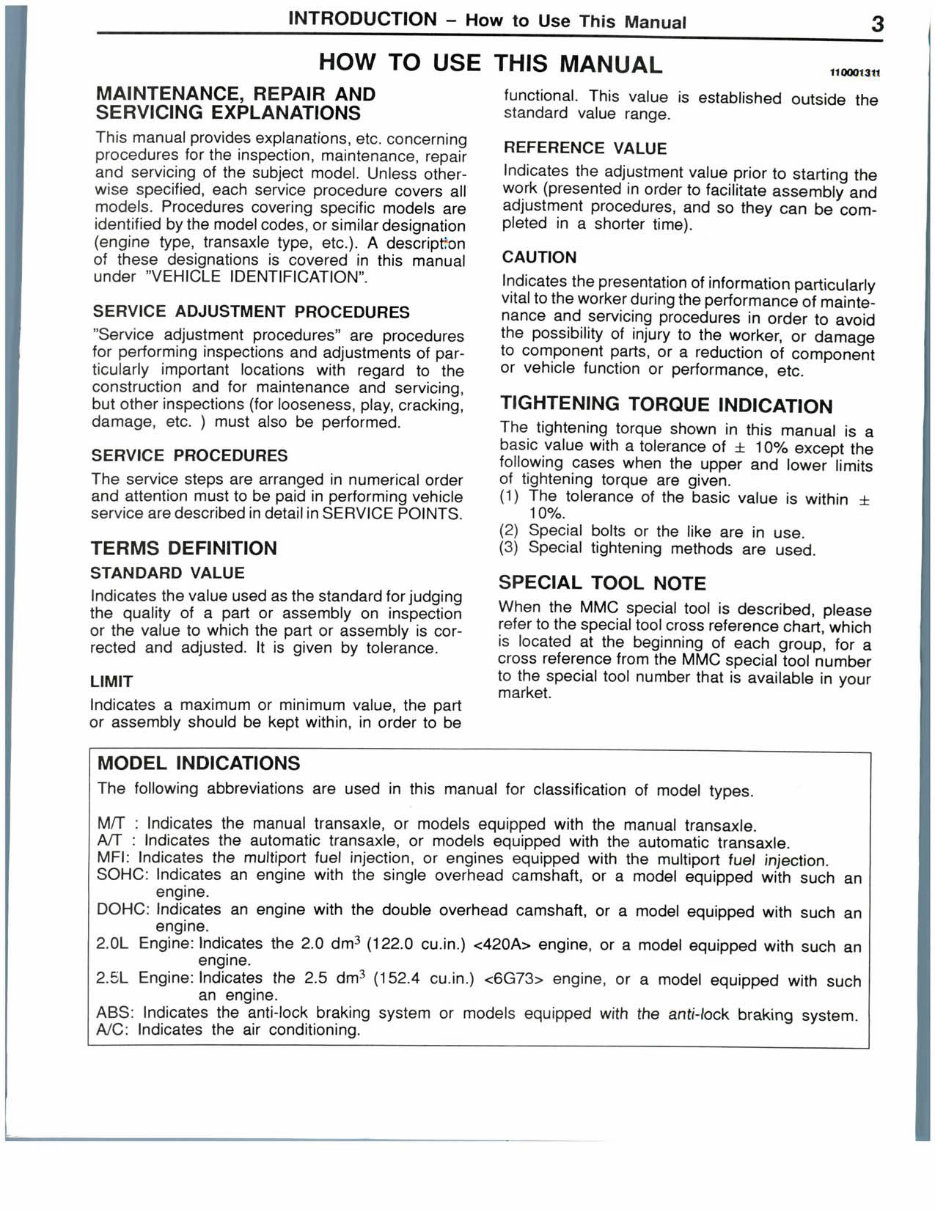
INTRODUCTION - How to Use This Manual HOW TO USE THIS MANUAL 110001311 MAINTENANCE, REPAIR AND SERVICING EXPLANATIONS This manual provides explanations, etc. concerning procedures for the inspection, maintenance, repair and servicing of the subject model. Unless other- wise specified, each service procedure covers all models. Procedures covering specific models are identified by the model codes, or similar designation (engine type, transaxle type, etc.). A description of these designations is covered in this manual under "VEHICLE IDENTIFICATION". SERVICE ADJUSTMENT PROCEDURES "Service adjustment procedures" are procedures for performing inspections and adjustments of par- ticularly important locations with regard to the construction and for maintenance and servicing, but other inspections (for looseness, play, cracking, damage, etc. ) must also be performed. SERVICE PROCEDURES The service steps are arranged in numerical order and attention must to be paid in performing vehicle service are described in detail in SERVICE POINTS. TERMS DEFINITION STANDARD VALUE Indicates the value used as the standard for judging the quality of a part or assembly on inspection or the value to which the part or assembly is cor- rected and adjusted. It is given by tolerance. LIMIT Indicates a maximum or minimum value, the part or assembly should be kept within, in order to be functional. This value is established outside the standard value range. REFERENCE VALUE Indicates the adjustment value prior to starting the work (presented in order to facilitate assembly and adjustment procedures, and so they can be com- pleted in a shorter time). CAUTION Indicates the presentation of information particularly vital to the worker during the performance of mainte- nance and servicing procedures in order to avoid the possibility of injury to the worker, or damage to component parts, or a reduction of component or vehicle function or performance, etc. TIGHTENING TORQUE INDICATION The tightening torque shown in this manual is a basic value with a tolerance of ± 10% except the following cases when the upper and lower limits of tightening torque are given. (1) The tolerance of the basic value is within ± 10%. (2) Special bolts or the like are in use. (3) Special tightening methods are used. SPECIAL TOOL NOTE When the MMC special tool is described, please refer to the special tool cross reference chart, which is located at the beginning of each group, for a cross reference from the MMC special tool number to the special tool number that is available in your market. MODEL INDICATIONS The following abbreviations are used in this manual for classification of model types. M/T : Indicates the manual transaxle, or models equipped with the manual transaxle. A/T : Indicates the automatic transaxle, or models equipped with the automatic transaxle. MFI: Indicates the multiport fuel injection, or engines equipped with the multiport fuel injection. SOHC: Indicates an engine with the single overhead camshaft, or a model equipped with such an engine. DOHC: Indicates an engine with the double overhead camshaft, or a model equipped with such an engine. 2.0L Engine: Indicates the 2.0 dm3 (122.0 cu.in.) <420A> engine, or a model equipped with such an engine. 2.5L Engine: Indicates the 2.5 dm3 (152.4 cu.in.) <6G73> engine, or a model equipped with such an engine. ABS: Indicates the anti-lock braking system or models equipped with the anti-lock braking system. A/C: Indicates the air conditioning.
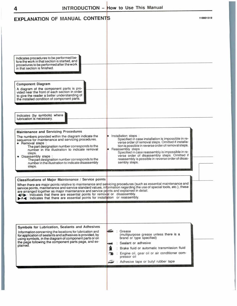
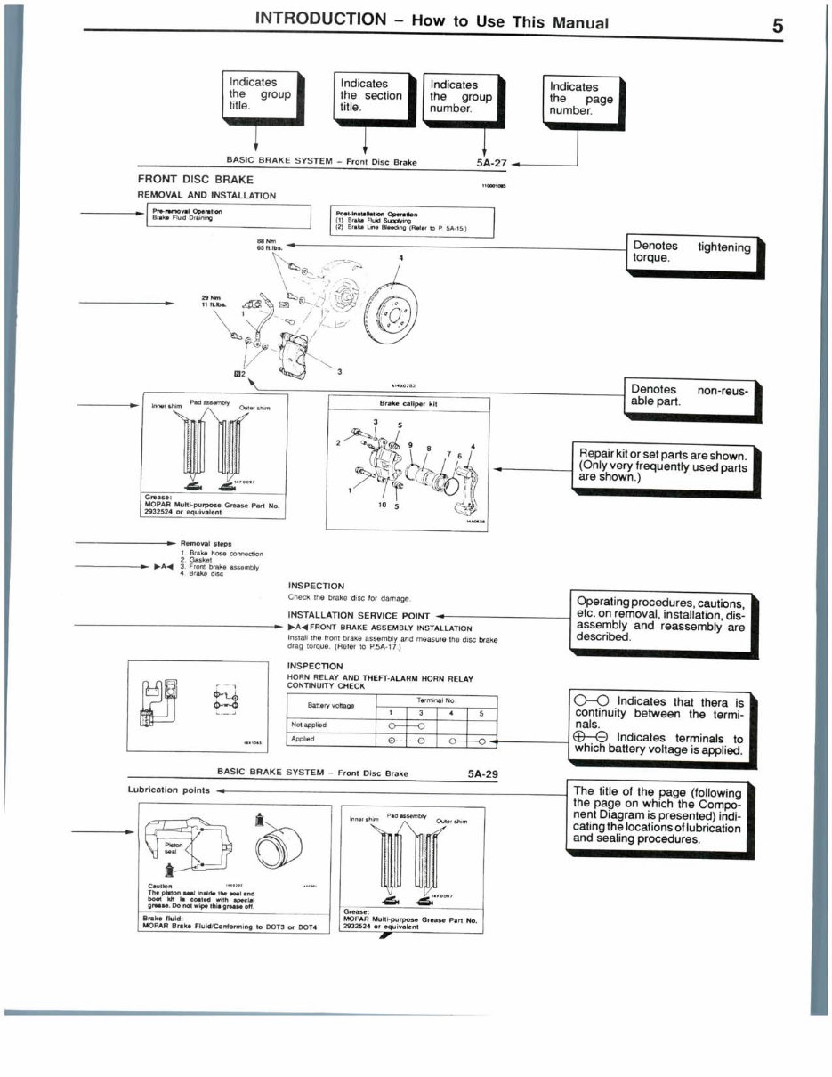
INTRODUCTION - How to Use This Manual EXPLANATION OF MANUAL CONTENTS 110001519 Indicates procedures to be performed be- fore the work in that section is started, and procedures to be performed after the work in that section is finished. Component Diagram A diagram of the component parts is pro- vided near the front of each section in order to give the reader a better understanding of the installed condition of component parts. Indicates (by symbols) where lubrication is necessary. Maintenance and Servicing Procedures The numbers provided within the diagram indicate the sequence for maintenance and servicing procedures. • Removal steps : The part designation number corresponds to the number in the illustration to indicate removal steps. • Disassembly steps : The part designation number corresponds to the number in the illustration to indicate disassembly steps. Classifications of Major Maintenance / Service points When there are major points relative to maintenance and se Installation steps : Specified in case installation is impossible in re- verse order of removal steps. Omitted if installa- tion is possible in reverse order of removal steps. Reassembly steps : Specified in case reassembly is impossible in re- verse order of disassembly steps. Omitted if reassembly is possible in reverse order of disas- sembly steps. vicing procedures (such as essential maintenance and service points, maintenance and service standard values, inl Drmation regarding the use of special tools, etc.), these are arranged together as major maintenance and service pc ints and explained in detail. Indicates that there are essential points for removal or disassembly. Indicates that there are essential points for installation or reassembly. Symbols for Lubrication, Sealants and Adhesives Information concerning the locations for lubrication and for application of sealants and adhesives is provided, by using symbols, in the diagram of component parts or on the page following the component parts page, and ex- plained. i Grease (multipurpose grease unless there is a brand or type specified) Sealant or adhesive Brake fluid or automatic transmission fluid Engine oil, gear oil or air conditioner com- pressor oil Adhesive tape or butyl rubber tape
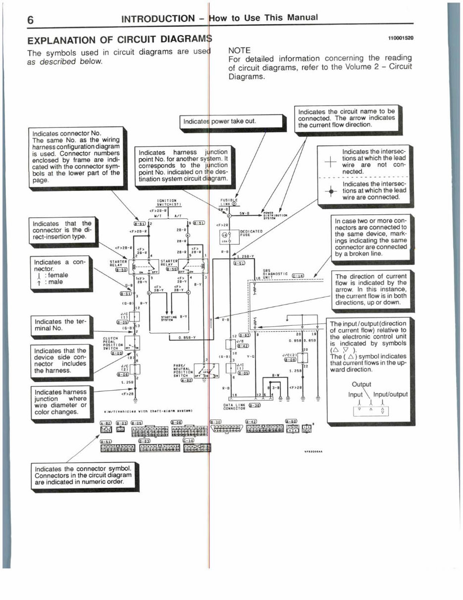
INTRODUCTION - How to Use This Manual Indicates power take out. Indicates harness junction point No. for another system. It corresponds to the junction point No. indicated on trie des- tination system circuit diagram. Indicates that the connector is the di- rect-insertion type. Indicates a con- nector. : female : male Indicates the ter- minal No. Indicates that the device side con- nector includes the harness. indicates harness junction where wire diameter or color changes. EXPLANATION OF CIRCUIT DIAGRAM The symbols used in circuit diagrams are as described below. 110001520 NOTE For detailed information concerning the reading of circuit diagrams, refer to the Volume 2 - Circuit Diagrams. Indicates connector No. The same No. as the wiring harness configuration diagram is used. Connector numbers enclosed by frame are indi- cated with the connector sym- bols at the lower part of the page. Indicates the circuit name to be connected. The arrow indicates the current flow direction. Indicates the intersec- tions at which the lead wire are not con- nected. Indicates the intersec- tions at which the lead wire are connected. In case two or more con- nectors are connected to the same device, mark- ings indicating the same connector are connected by a broken line. The direction of current flow is indicated by the arrow. In this instance, the current flow is in both directions, up or down. The input/output(direction of current flow) relative to the electronic control unit is indicated by symbols (A y ). The ( A) symbol indicates that current flows in the up- ward direction. Output Input \t Jl Jl Jl Indicates the connector symbol. Connectors in the circuit diagram are indicated in numeric order.
INTRODUCTION -- How to Use Troubleshooting/Inspection Service Points 7 HOW TO USE TROUBLESHOOTING/INSPECTION SERVICE POINTS 110000008 Troubleshooting of electronic control systems for which the scan tool can be used follows the basic outline described below. Furthermore, even in systems for which the scan tool cannot be used, part of these systems still follow this outline. TROUBLESHOOTING CONTENTS 1. STANDARD FLOW OF DIAGNOSTIC TROUBLESHOOTING The main procedures for diagnostic troubleshooting are shown. 2. SYSTEM OPERATION AND SYMPTOM VERIFICATION TESTS If verification of the trouble symptoms is difficult, procedures for checking operation and verifying trouble symptoms are shown. 3. DIAGNOSTIC FUNCTION The following diagnostic functions are shown. • Method of reading diagnostic trouble codes • Method of erasing diagnostic trouble codes • Input inspection service points 4. INSPECTION CHART FOR DIAGNOSTIC TROUBLE CODES 5. INSPECTION PROCEDURE FOR DIAGNOSTIC TROUBLE CODES Indicates the inspection procedures corresponding to each diagnostic trouble code. (Refer to the next page on how to use the inspection procedures.) 6. INSPECTION CHART FOR TROUBLE SYMPTOMS If there are trouble symptoms, even though the results of inspection using the scan tool show that all diagnostic trouble codes are normal, inspection procedures for each trouble symptom will be found by means of this chart. 7. INSPECTION PROCEDURE FOR DIAGNOSTIC SYMPTOM Indicates the inspection procedures corresponding to each trouble symptoms classified in the Inspection Chart for Trouble Symptoms. (Refer to the next page on how to use the inspection procedures.) 8. SERVICE DATA REFERENCE TABLE Inspection items and normal judgement values have been provided in this chart as reference information. 9. CHECK AT ECU TERMINALS Terminal numbers for the ECU connectors, inspection items and standard values have been provided in this chart as reference information. Terminal Voltage Checks 1. Connect a needle-nosed wire probe or paper clip to a voltmeter probe. 2. Insert the needle-nosed wire probe into each of the ECU connector terminals from the wire side, and measure the voltage while referring to the check chart. NOTE 1. Measure voltage with the ECU connectors connected. 2. You may find it convenient to pull out the ECU to make it easier to reach the connector terminals. 3. Checks don't have to be carried out in the order given in the chart. Caution Short-circuiting the positive (+) probe between a connector terminal and ground could damage the vehicle wiring, the sensor, the ECU, or all three. Use care to prevent this ! 3. If voltage readings differ from Normal Condition values, check related sensors, actuators, and wiring, then replace or repair. 4. After repair or replacement, recheck with the voltmeter to confirm that the repair has corrected the problem.
8 INTRODUCTION - How to Use Troubleshooting/Inspection Service Points Terminal Resistance and Continuity Checks 1. Turn the ignition switch to off. 2. 3. vehicle wiring, sensors, ECU, and/or itinuity between the terminals of the ECU harness-side hart. Disconnect the ECU connector. Measure the resistance and check for co connector while referring to the check c NOTE Checks don't have to be carried out in the order given in the chart. Caution If resistance and continuity checks an performed on the wrong terminals, damage to the ohmmeter may occur. Use care to prevent this! 4. If the ohmmeter shows any deviation frolri the Normal Condition value, check the corresponding sensor, actuator and related electrical wiring, then repair or replace. 5. After repair or replacement, recheck witr| the ohmmeter to confirm that the repair has corrected the problem. 10. INSPECTION PROCEDURES USING AN OSCILLOSCOPE When there are inspection procedures usinfj an oscilloscope, these are listed here.
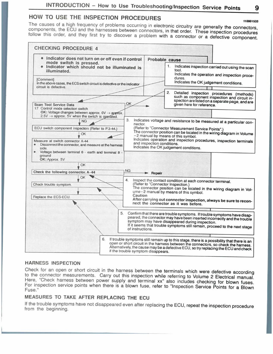
INTRODUCTION - How to Use Troubleshooting/Inspection Service Points 110001533 HOW TO USE THE INSPECTION PROCEDURES The causes of a high frequency of problems occurring in electronic circuitry are generally the connectors, components, the ECU and the harnesses between connectors, in that order. These inspection procedures follow this order, and they first try to discover a problem with a connector or a defective component. CHECKING PROCEDURE 4 * indicator does not turn on or off even if control mode switch is pressed. • Indicator which should not be illuminated is illuminated. fComment] Inthe abovecases, theECSswitch ci rcuit is defective or the indicator circuit is defective. Probable cause Scan Tool Service Data 17 Control mode selecfon s\witch OK: Voltage changes between approx 0V -> app*6x. 2,5V '-> approx> 5V when the switch is operated. NG ECU switch component inspection {Refer to P.3-44,) OK Measure at switch connector A-44 • Disconnect the connector, and measure at the harness side. | Voftage between terminal 6 - earth and terminal 8 - ground I OK: Approx. 5V 1. Indicates inspection carried out using the scan tool. Indicates the operation and inspection proce- dures. Indicates the OK judgement conditions. { I 2. Detailed inspection procedures (methods) such as component inspection and circuit in- spection are listed on a separate page, and are given here for reference. 3. Indicates voltage and resistance to be measured at a particular con- nector. (Refer to "Connector Measurement Service Points".) The connector position can be located in the wiring diagram in Volume -2 manual by means of this symbol. Indicates operation and inspection procedures, inspection terminals and inspection conditions. Indicates the OK judgement conditions. i OK Check flic following connector, A-44 Repair OK Check trouble symptom. Replace the ECS-ECU. 4. Inspect the contact condition at each connector terminal. (Refer to "Connector Inspection.) The connector position can be located in the wiring diagram in Vol- ume-2 manual by means of this symbol. Caution After carrying out connector inspection, always be sure to recon- nect the connector as it was before. 5. Confirm that there are trouble symptoms. If trouble symptoms have disap- peared, the connector may have been inserted incorrectly and the trouble symptom may have disappeared during inspection. If it seems that trouble symptoms still remain, proceed to the next stage of instructions. If trouble symptoms still remain up to this stage, there is a possibility that there is an open or short circuit in the harness between the connectors, so check the harness. Alternatively, the cause may be a defective ECU, so try replacing the ECU and check if the trouble symptom disappears. HARNESS INSPECTION Check for an open or short circuit in the harness between the terminals which were defective according to the connector measurements. Carry out this inspection while referring to Volume 2 Electrical manual. Here, "Check harness between power supply and terminal xx" also includes checking for blown fuses. For inspection service points when there is a blown fuse, refer to "Inspection Service Points for a Blown Fuse." MEASURES TO TAKE AFTER REPLACING THE ECU If the trouble symptoms have not disappeared even after replacing the ECU, repeat the inspection procedure from the beginning.
10 INTRODUCTION - How to Use Troubleshooting/Inspection Service Points COIfNECTOR MEASUREMENT SERVICE POINTS 110000010 Turn Ithe ignition switch to OFF when connecting and discon- necting the connectors, and turn the ignition switch to ON wherl measuring if there are no instructions to the contrary. Harness connector 01R0450 Extra-thin probe Connector Inspection harness for connector pin contact pressure IF INSPECTING WITH THE CONNECTOR CONNECTED (WITH CIRCUIT IN A CONDITION OF CONTINUITY) Waterproof Connectors Be sure to use the special tool (harness connector). Never inseift a test probe from the harness side, because to do so w II reduce the waterproof performance and result in corro- sion Ord nary (non-waterproof) Connectors Che ;k by inserting the test probe from the harness side. Not? that if the connector (control unit, etc.) is too small to perriit insertion of the test probe, it should not be forced; use a special tool (the extra-thin probe in the harness set for checking) for this purpose. IF INSPECTING WITH THE CONNECTOR DISCONNECTED <When Inspecting a Female Pin> Use! the special tool (inspection harness for connector pin ict pressure in the harness set for inspection), inspection harness for connector pin contact pressure ild be used. The test probe should never be forcibly in- con! The sho sert as it may cause a defective contact. <Wnen Inspecting a Male Pin> Touch the pin directly with the test bar. Caution At his time, be careful not to short the connector pins witli the test probes. To do so may damage the circuits inside the ECU.
This 1998 Dodge Avenger Service & Repair Manual Software is a comprehensive guide that provides detailed instructions and diagrams for repairing and maintaining your Dodge Avenger model. Whether you are a DIY enthusiast or a professional mechanic, this software is designed to assist you in troubleshooting and fixing any issues with your vehicle.
With this software, you can access step-by-step instructions for various repair procedures, including engine overhaul, electrical system troubleshooting, brake repair, suspension and steering, and much more. It covers all aspects of your vehicle's service, allowing you to save time and money by performing repairs on your own.
Some of the models covered in this software include:
1998 Dodge Avenger Base Model
1998 Dodge Avenger ES Model
1998 Dodge Avenger ES Sport Model
Each repair procedure is accompanied by detailed diagrams, illustrations, and photographs to help you understand the process better. Additionally, the software provides specifications, torque values, and other technical information necessary for a successful repair.
Whether you are facing a minor issue or need to perform major repairs, the 1998 Dodge Avenger Service & Repair Manual Software has got you covered. Get your copy today and ensure your Dodge Avenger is running smoothly and efficiently.
Recently Viewed
5,521,897Happy Clients
2,594,462eManuals
1,120,453Trusted Sellers
15Years in Business
Price:
Actual Price:
1998 Dodge Avenger Service & Repair Manual Software