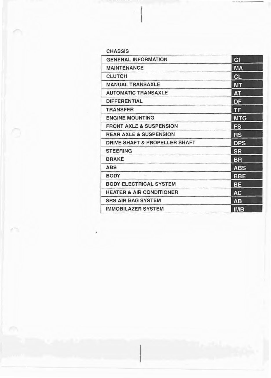
CHASSIS GENERAL INFORMATION MAINTENANCE CLUTCH MANUAL TRANSAXLE AUTOMATIC TRANSAXLE DIFFERENTIAL TRANSFER ENGINE MOUNTING FRONT AXLE & SUSPENSION REAR AXLE & SUSPENSION DRIVE SHAFT & PROPELLER SHAFT STEERING BRAKE ABS BODY BODY ELECTRICAL SYSTEM HEATER & AIR CONDITIONER SRS AIR BAG SYSTEM IMMOBILAZER SYSTEM
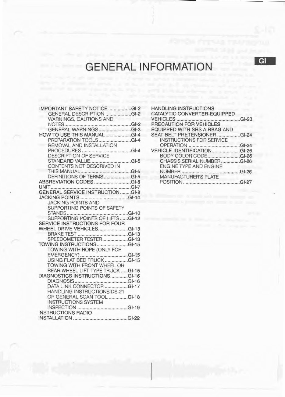
GENERAL INFORMATION IMPORTANT SAFETY NOTICE .................GI-2 GENERAL DESCRIPTION ...................GI-2 WARNINGS, CAUTIONS AND NOTES ................................................. GI-2 GENERAL WARNINGS ........................ GI-3 HOW TO USE THIS MANUAL ................... GI-4 PREPARATION TOOLS ........................ GI-4 REMOVAL AND INSTALLATION PROCEDURES ................................... .GI-4 DESCRIPTION OF SERVICE STANDARD VALUE.............................. GI-5 CONTENTS NOT DESCAIVED IN THIS MANUAL ..................................... GI-5 DEFINITIONS OF TERMS ....................GI-5 ABBREVIATION CODES ...........................GI-6 UNIT ........................................................... GI-7 GENERAL SERVICE INSTRUCTION ........ GI-8 JACKING POINTS .................... .. ............. GI-1 0 JACKING POINTS AND SUPPORTING POINTS OF SAFETY STANDS ............................................. GI-10 SUPPORTING POINTS OF LIFTS ...... GI-12 SERVICE INSTRUCTIONS FOR FOUR WHEEL DRIVE VEHICLES ...................... GI-13 BRAKE TEST ..................................... GI - 13 SPEEDOMETER TESTER ................... GI-13 TOWING INSTRUCTIONS ....................... GI-15 TOWING WITH ROPE (ONLY FOR EMERGENCY) ...................................GI-15 USING FLAT BED TRUCK .................GI- 15 TOWING WITH FRONT WHEEL OR REAR WHEEL LIFT TYPE TRUCK ..... GI-15 DIAGNOSTICS INSTRUCTIONS ............. GI-16 DIAGNOSIS ....................................... GI-16 DATA LINK CONNECTOR ................. GI-17 HANDLING INSTRUCTIONS OS-21 OR GENERAL SCAN TOOL .............. GI-18 INSTRUCTIONS SYSTEM INSPECTION ..................................... GI-19 INSTRUCTIONS RADIO INSTALLATION ........................................GI-22 HANDLING INSTRUCTIONS CATALYTIC CONVERTER-EQUIPPED VEHICLES ............................................... GI-23 PRECAUTION FOR VEHICLES EQUIPPED WITH SRS AIRBAG AND SEAT BELT PRETENSIONER ................. GI-24 INSTRUCTIONS FOR SERVICE OPERATION ...................................... GI-24 VEHICLE IDENTIFICATION .....................GI-26 BODY COLOR CODE ........................ Gt-26 CHASSIS SERIAL NUMBER ..............Gf-26 ENGINE TYPE AND ENGINE NUMBER ...........................................GI-26 MANUFACTURER'S PLATE POSITION ... ............................... .. ......GI-27
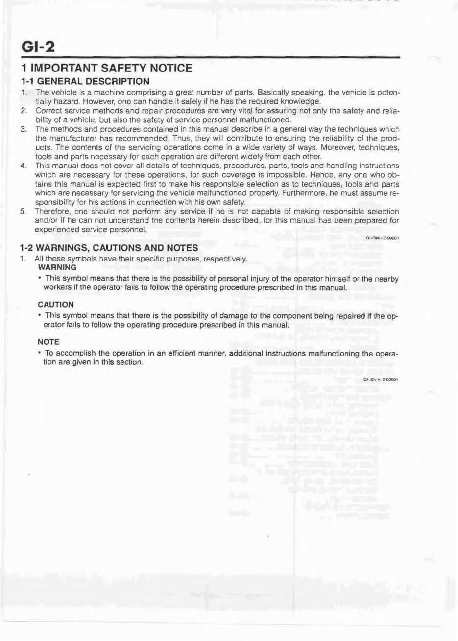
Gl-2 1 IMPORTANT SAFETY NOTICE 1-1 GENERAL DESCRIPTION - .. .. .. - . . - -- _,. -- -- 1. The vehicle is a machine comprising a great number of parts. Basically speaking, the vehicle is poten- tially hazard. However, one can handle it safely 1f he has the required knowledge. 2. Correct service methods and repair procedures are very v1tal for assuring not only the safety and relia- bility of a vehicle but also the safety of serv1ce personnel malfunctioned. 3. The methods and procedures contained in this manual describe 1n a general way lhe techniques which the manufacturer has recommended. Thus, they will contribute to ensuring the reliability of the prod- ucts. The contents of the servicing operations come in a wide variety of ways. Moreover, techniques, tools and parts necessary for each operation are different widely from each other. 4. This manual does not cover all details of techniques. procedures, parts, tools and handling instructions which are necessary for these operations, for such coverage is impossible. Hence. any one who ob- tains this manual is expected first to make his responsible selection as to techniques tools and parts which are necessary for servicing the vehicle malfunctioned properly. Furthermore, he must assume re- sponsibility tor his actions in connect1on with his own safety. 5. Therefore, one should not perform any service if he is not capable of making responsible selection and/or if he can not understand the contents herein described, for this manual has been prepared for experienced service personnel 1·2 WARNINGS, CAUTIONS AND NOTES 1. All these symbols have their specific purposes, respectively. WARNING • This symbol means that there is the possibility of personal injury of the operator himself or the nearby workers if the operator fails to follow the operating procedure prescribed in this manual. CAUTION • This symbol means that there is the possibility of damage to the component being repaired if the op- erator fails to follow the operating procedure prescribed in this manual. NOTE • To accomplish the operation in an efficient manner, additional instructions malfunctioning the opera- tion are given in this section.
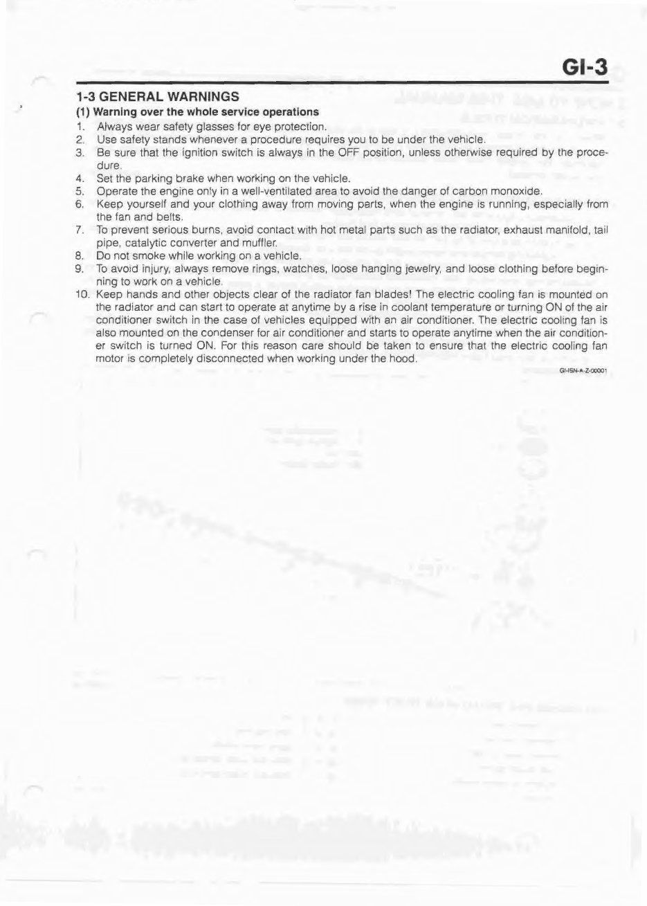
1-3 GENERAL WARNINGS (1) Warning over the whole service operations 1. Always wear safety glasses lor eye protection. 2 Use safety stands whenever a procedure requires you to be under the vehicle. Gl-3 3 Be sure that the ignition switch is always fn Lhe OFF position, unless otherwise required t:Jy the proce- dure. 4. Set the parking brake when working on the vehicle. 5. Operate the engine only in a well-ventilated area to avoid the danger of carbon monoxide. 6. Keep yourself and your clothing away from moving parts, when the engine Is running, especially from the fan and belts. 7. To prevent serious burns, avoid contact w1th hot metal parts such as the radiator, exhaust manifol d. ta il pipe. catalytic convener and muffler. 8. Do not smoke while working on a vehicle. 9. To avo1d injury, always remove r1ngs . watches, loose hanging Jewelry, and loose clot hi ng before begrn - ning to work on a vehicle. 10. Keep hands and other ObJects clear of the radiator fan blades! The electric coo li ng tan is mounted on the radiator and can start to operate at anytime by a rise in coolant temperature or turning ON of the air conditioner switch in the case of vehicles equipped with an air condrtroner. The electric cooling fan IS also mounted on the condenser for air conditioner and starts to operate anyti me when the air condition- er switch is turned ON. For this reason care should be taken to ensure that the electric cooling fan motor is completely disconnected when workrng under the hood.
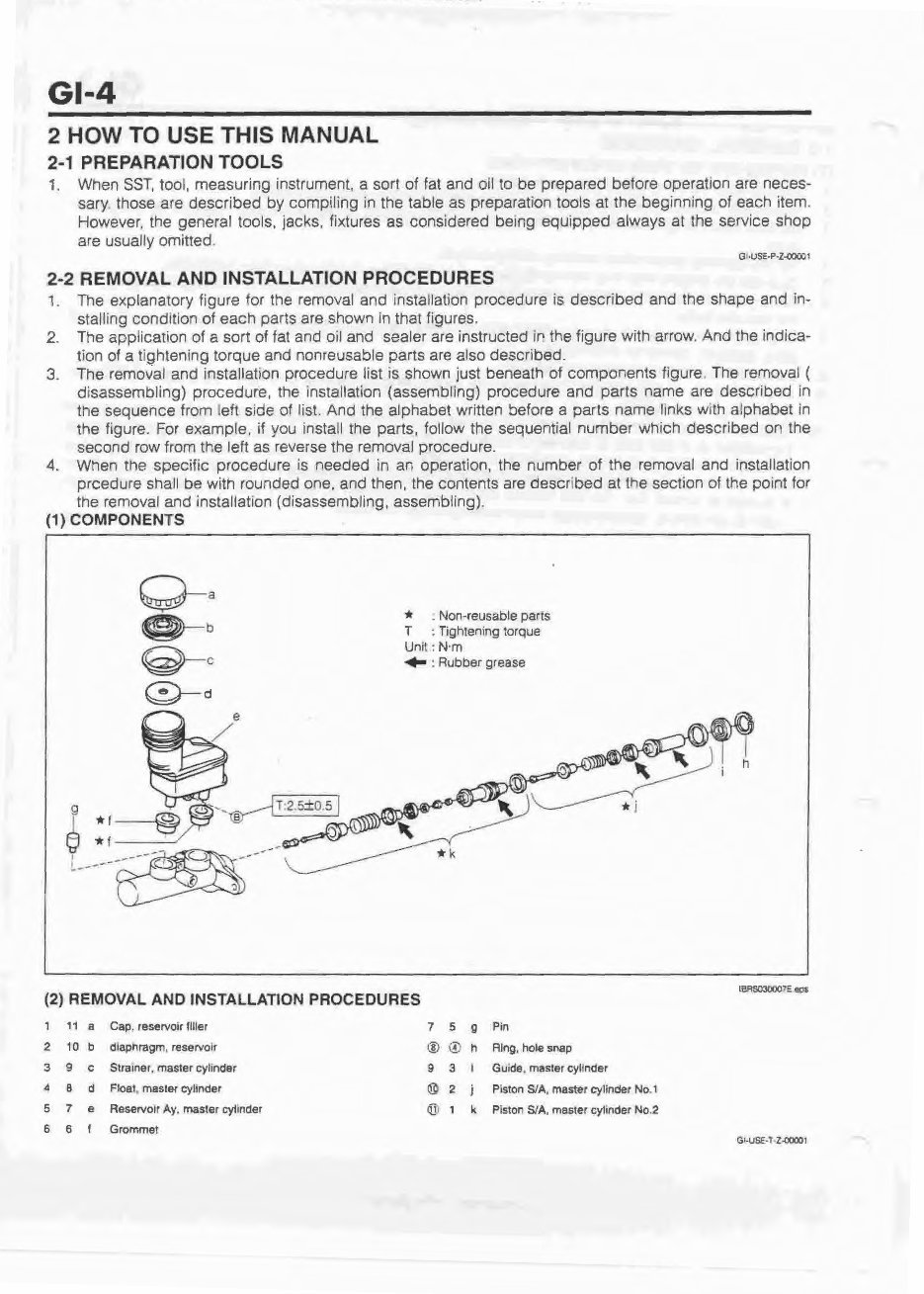
Gl-4 2 HOW TO USE THIS MANUAL 2-1 PREPARATION TOOLS 1. When SST, tool, measuring instrument, a sort of fat and on to be prepared before operation are neces- sary those are described by compiling in the table as preparation toots at the beginning of each item. However, the general tools, jacks. fixtures as considered bemg equipped always at the seNice shop are usually omitted. 2-2 REMOVAL AND INSTALLATION PROCEDURES 1 The explanatory figure for the removal and installation procedure is described and the shape and in- stalling condition of each parts are shown in that figures. 2. The application of a sort of fat and oil and sealer are instructed in the figure with arrow. And the indica- tion of a tightening torque and nonreusable parts are also described. 3 The removal and Installation procedure list is shown just beneath of components figure The removal ( disassembling) procedure, the tnstallation (assembling) procedure and parts name are described tn the sequence from left side of list. And the alphabet written before a parts name links wrth alphabet in the figure. For example, if you install the parts, follow the sequential number which described on the second row from the left as reverse the removal procedure. 4. When the specific procedure is needed in an operation, the number of the removal and installation prcedure shall be with rounded one. and then, the contents are descnbed at the section of the point for the removal and installation (disassembling, assembling). (1) COMPONENTS Q-a e- b ~c * . Non-reusable parts T Tightening torque U nlt . N·m + · Rubber grease 0-d e / (2) REMOVAL AND INSTALLATION PROCEDURES 1 11 a Cap. reservoir III Ier 2 10 b dfapnragm, reservoir 3 9 c Slramer, master cylinder A 8 d Float master cylinder 5 7 e Reservoir Ay. master cylinder 6 6 f Grommet 7 5 g Pin ® @ h Ring, hole snap 9 3 I Gurde, master cylinder @ 2 Piston S/A, master cylinder No.1 @ 1 k Pi ston S/A, master cylinder No.2 IBRS030007E <!(II
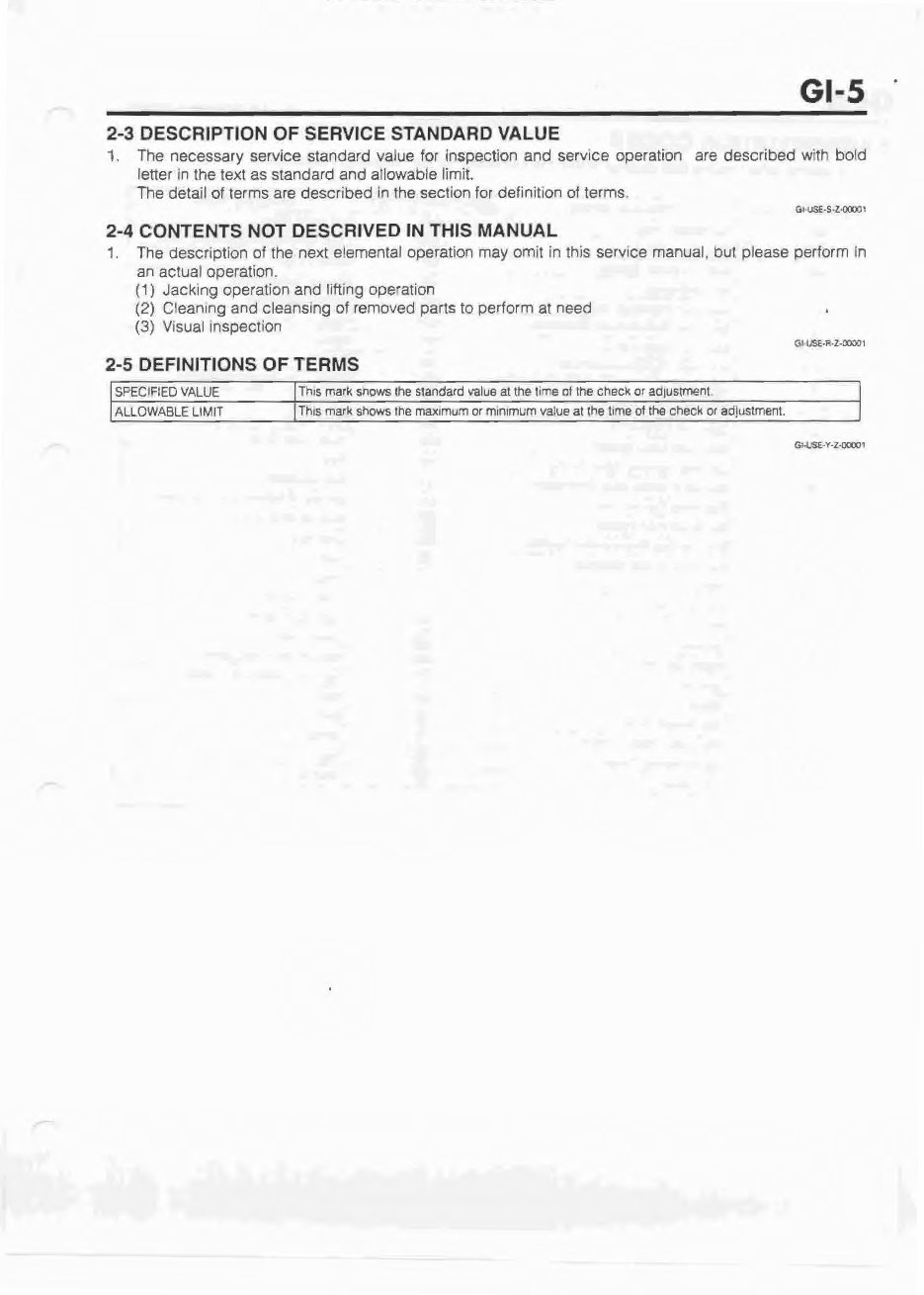
---- - -- --- - -.... - --- -... ··-- GI·S 2-3 DESCRIPTION OF SERVlCE STANDARD VALUE 1. The necessary service standard value for inspection and service operation are described with bold letter in the text as standard and allowable limit. The detail of terms are described in the section for definition of terms. GI· USE·S· Z·OOOCil 2-4 CONTENTS NOT DESCRIVED IN THIS MANUAL 1. The description of the next elemental operation may omit in this service manual, but please perform In an actual operation. (1) Jacking operation and litting operation (2) Cleantng and cleanstng of removed parts to perform at need (3) Visual Inspection 2-5 DEFINITIONS OF TERMS SPECIFIED VALUE Thts rnark shows the standard value at the time of the check or adJ UStment ALLOWABLE LIMIT Thts mark shows the maxt mum or mtntmum value at the lime of the check or adjustment. Gl USE-R·Z-00001 c;;.use: .y .z. oocxn
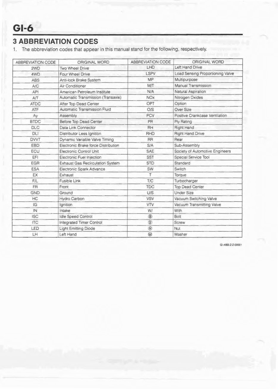
Gl-6 3 ABBREVIATION CODES 1. The abbreviation codes that appear in this manual stand for the following. respectively. ABBREVIATION CODE ORIGINAL WORD ABBREVIATION CODE ORIGINAL WORD 2WD Two Wheel Drive LHD Left Hand Drive 4WD Four Wneel Onve LSPV Load Senstng Proportionrng Valve ASS Anti-look Brake System MP Mulupurpose AJC Air Condltlof!er M[f Manual Transmission API Amerrcan Petroleum InstitUte N/A Natural Asptrauon AJT Automatic Transmission (Transaxle) NOx Nttrogen Oxides ATDC Alter Top Dead Center OPT Option ATF Automaltc Transmisston Fluid 0/S Over Size Ay Assembly PCV Positive Crankcase Ventilation BTDC Before Top Dead Center PR Ply Rattng DLC Dala Ltn~ Connector RH Rtght Hand Dll Drstributor Less lgnttion I RHO Right Hand Dnve DVVT Dynamic Vanable Valve Timing RA Rear EBD Electronic BraKe force Dtstrrbuuon S/A Sub-Assembly ECU Elecuomc Control Unit SAE Soc1ety of AutomotiVe Engineers EFt Electronic Fuel Injection SST Special Serv1ce Tool EGA Exhaust Gas Rectrculatlon System STD Standard ESA Electronic Spark Advance SW Switch EX Exhaust T Torque F/L Fusi ble Unk T/C Turbocharger FA Front me Top Dead Center GND Ground U/S Under Size HC Hydro Carbon vsv Vacuum Switching Valve IG tgnttion VTV Vacuum Transmiwng Valve IN Intake WI Wtth ISC Idle Speed Control ® Bolt lTC Integrated T1mer Control ® Screw LED Ltght Emitttng Diode ® Nut LH Left Hand @ Washer
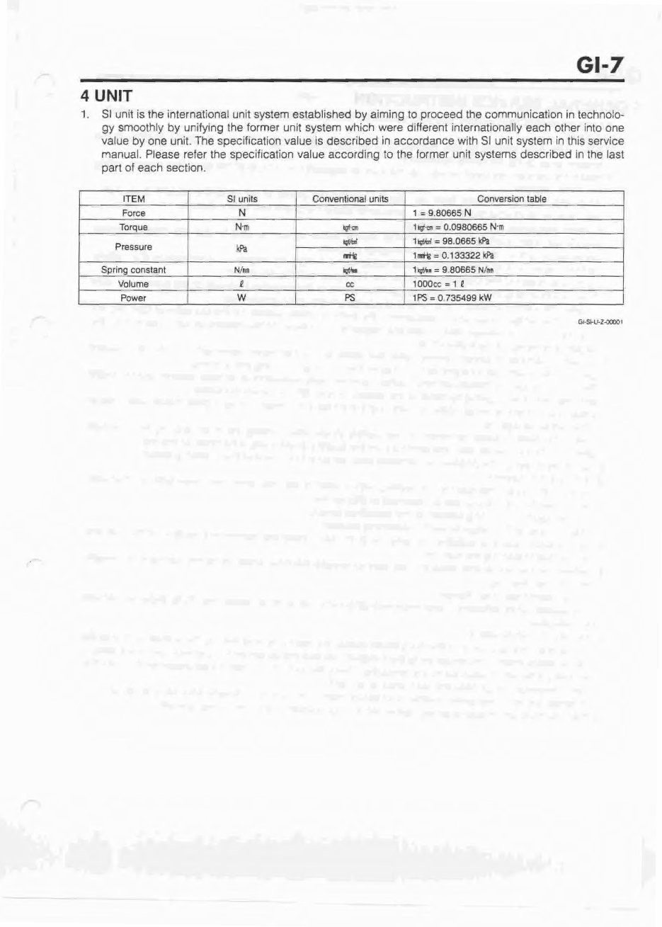
Gl-7 4 UNIT 1 Sf unit is the international unit system established by aiming to proceed the communication in technolo~ gy smoothly by unify1ng the former unit system which were oifferent internationally each other into one value by one unit. The specification value is described in accordance with Sl unit system in lh1s service manual. Please reier the specification value according to the former unit systems described In the last part of each section. ITEM Sl units Conventional umts Conversion table Force N 1 =- 9.80665 N Torque N·m kQI• cm 1 i;f'OII = 0.0980665 N·m Pressure kfa ~ 1~= 98.0665 kPa lftiiJe 1~ = 0.133322 kPa Spring constant N/m11 ~ ... 1~ = 9.80665 N!n Volume £ cc 1 OOOc:c = 1 e Power w PS 1PS =0.735499 kW
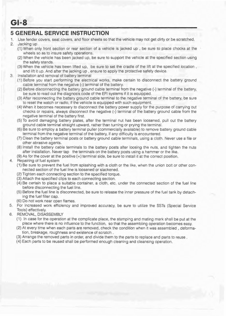
Gl-8 5 GENERAL SERVICE INSTRUCTION 1. Use fender covers. seat covers. and floor sheets so that the vehicle may not get dirty or be scratched. 2. Jacking up ( 1) When only front section or rear section of a vehicle Is jacked up be sure to place chocks at the wheels so as to insure safety operations. (2) When the vehicle has been jacked up, be sure to support the vehicle at the specrfied section using the satery stands. (3) When the vehicle has been lifted up , be sure to set the cradle of the lift at the specified location . and lift it up. And after the jacking up , ensure to apply the protective safety device. 3 Installation and removal of battery terminal ( 1) Before you start performing the electrical works, make certain to disconnect the battery ground cable terminal from the negative(-) terminal of the battery. (2) Before disconnecting the battery ground cable terminal from the negative(-) terminal of the battery, be sure to read out the diagnosis code of the EFI systems if it is equi pped . (3) After reconnecting the battery ground cable terminal to the negative terminal of the battery, be sure to reset the watch or radio. if the vehicle is equipped with such equipment. (4) When it becomes necessary to disconnect the battery power supply for the purpose of carrying out checks or repairs, always disconnect the negative (-) terminal of the battery ground cable from the negative terminal of the battery first. (5) To avoid damaging battery plates, after the terminal nut has been loosened, pull out the battery ground cable terminal strarght upward, rather than turning or pry1ng the terminal. (6) Be sure to employ a battery terminal puller (commercially available) to remove battery ground cable terminal from the negative terminal of the battery, if any difficulty is encountered. (7) Clean the battery terminal posts or battery ground cable terminals, using a cloth. Never use a file or other abrasive agents. (8) Install the battery cable terminals to the battery posts after loosing the nuts. and tighten the nuts after installation. Never tap the terminals on the battery posts us1ng a hammer or the like. (9) As for the cover at the positive ( +) terminal side, be sure to install it at the correct position. 4 Repairing of fuel system (1) Be sure to prevent the fuel from splashing with a cloth or the l1ke, when the union bolt or other con- nected section of the fuel line is loosened or slackened. (2) Tighten each connecting section to the specified torque (3) Attach the specified clips to each connecting section. (4) Be certain to place a suitable container. a cloth, etc. under the connected section of the fuel line before disconnecting the fuel line. (5) Beiore the fuel line is disconnected. be sure to release the 1nner pressure of the fuel tank by detach- ing the fuel filler cap. (6) Do not work near open flames. 5. For increased work efficiency and improved accuracy, be sure to ut11ize the SSTs (Special Service Tools) effectively. 6. REMOVAL, DISASSEMBLY ( 1 ) In case for the operation at the complicate place, the stamping and mating mark shall be put at the place where there is no influence to the function. so that the assembling operation becomes easy. (2) At every time when each parts are removed, check the conditron when it was assembled, deforma- tion, breakage, roughness and existence of scratch . (3) Arrange the removed parts in order, and divide them to the parts to replace and parts to reuse . ( 4) Each parts to be reused shall be performed enough cleaning and cleansing operation.
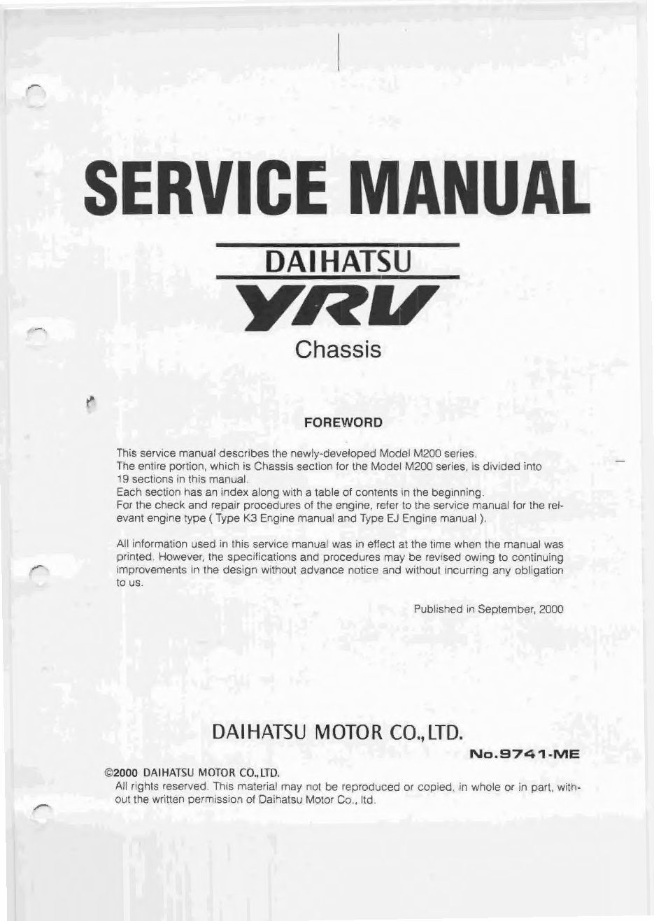
This workshop service and repair manual is designed for the Daihatsu YRV (Model M200) produced between 2000 and 2005. It covers all styles, models, and engines of the vehicle. The manual is a comprehensive resource for both professional mechanics and DIY enthusiasts.
Featuring over 940 pages, this manual provides detailed illustrations and step-by-step instructions for repair procedures. It is a valuable source of information for maintaining and servicing the vehicle, offering numbered instructions, cautions, warnings, and bold figure numbers to facilitate easy navigation. The manual also includes troubleshooting and electrical service procedures, along with detailed wiring diagrams for the machine's electrical system.
Available in a downloadable PDF format, this manual is compatible with all PC-based Windows operating systems and Mac. It is also printable, allowing users to have the necessary information on hand in the garage or workshop. The manual is DRM-free and without any restrictions, making it a convenient and reliable resource for vehicle maintenance and repair.


 Lifetime Access


