SECTION INDEX SECTION NAME GENERAL INFORMATION MAINTENANCE ENGINE MECHANICAL EMISSION CONTROL EFI SYSTEM LUBRICATION SYSTEM COOLING SYSTEM IGNITION SYSTEM STARTING SYSTEM CHARGING SYSTEM CLUTCH MANUAL TRANSMISSION AUTOMATIC TRANSMISSION TRANSMISSION & TRANSFER PROPELLER SHAFT FRONT & REAR DIFFERENTIAL FRONT AXLE & SUSPENSION REAR AXLE & SUSPENSION BRAKE (Including A.B.S) STEERING BODY BODY ELECTRICAL HARNESS & WIRING DIAGRAM SECTION GI MA EM EC EF LU CO IG ST CH CL MT AT TR PR DF FS RS BR SR BO BE HW ( Including Airbag system ) and immobilizer system DAIHATSU J100 Downloaded from www.Manualslib.com manuals search engine
DAIHATSU SERVICE MANUAL FOREWORD This service manual describes the maintenance and servicing procedures for the Model J100. Applicable Model: J100 In this service manual, the entire portion is divided into 23 sections. Each section has an index along with a table of contents at the beginning. For easier reference, the upper part of each page bears the section title concerned. All information used in this service manual was in effect at the time when the manual was printed. However, the specifications and procedures may be revised due to continuing im- provements in the design without advance notice and without incurring any obligation to us. Published in June, 1997 DAIHATSU MOTOR CO., LTD. NO. 9710-JE J100 Downloaded from www.Manualslib.com manuals search engine
GENERAL INFORMATION IMPORTANT SAFETY NOTICE .................... GI– 2 WARNINGS, CAUTIONS AND NOTES..... GI– 2 HOW TO USE THIS MANUAL ...................... GI– 4 CONTENTS OF EXPLANATION .............. GI– 4 ABBREVIATION CODES ............................. GI– 6 GENERAL SERVICE INSTRUCTION .......... GI– 7 HANDLING INSTRUCTIONS ON CATALYTIC CONVERTER ......................... GI– 8 JACKING POINTS AND SUPPORTING POINTS OF SAFETY STANDS ................. GI– 9 MODEL VARIATION ..................................... GI–13 CHASSIS SERIAL NUMBER STAMPED POSITION ..................................................... GI–14 MANUFACTURER’S PLATE POSITION ....... GI–14 CONTENTS OF MANUFACTURER’S PLATE ....................................................... GI–14 ENGINE NUMBER AND ENGINE TYPE STAMPED POSITIONS...............................GI–15 BODY COLOR INFORMATION ......................GI–15 COLOR CODE IN THE WORLD ................GI–16 TRIM CODE ....................................................GI–16 DAIHATSU GI JGI00001-00000 NO. 9710-JE J100 Downloaded from www.Manualslib.com manuals search engine
IMPORTANT SAFETY NOTICE The vehicle is a machine comprising a great number of parts. Basically speaking, the vehicle is potentially hazard. However, one can handle it safely if he has the required knowledge. Correct service methods and repair procedures are very vital for assuring not only the safety and reliability of a vehicle, but also the safety of service personnel concerned. The methods and procedures contained in this manual describe in a general way the techniques which the manufacturer has recommended. Thus, they will contribute to ensuring the reliability of the products. The contents of the servicing operations come in a wide variety of ways. Moreover, techniques, tools and parts necessary for each operation are different widely from each other. This manual does not cover all details of techniques, procedures, parts, tools and handling instruc- tions which are necessary for these operations, for such coverage is impossible. Hence, any one who obtains this manual is expected first to make his responsible selection as to techniques, tools and parts which are necessary for servicing the vehicle concerned properly. Furthermore, he must assume responsibility for his actions in connection with his own safety. Therefore, one should not perform any service if he is not capable of making responsible selection and/or if he can not understand the contents herein described, for this manual has been prepared for experienced service personnel. WARNINGS, CAUTIONS AND NOTES All these symbols have their specific purposes, respectively. WARNING: • This symbol means that there is the possibility of personal injury of the operator himself or the nearby workers if the operator fails to follow the operating procedure prescribed in this manual. CAUTION: • This symbol means that there is the possibility of damage to the component being repaired if the operator fails to follow the operating procedure prescribed in this manual. NOTE: • To accomplish the operation in an efficient manner, additional instructions concerning the operation are given in this section. The following list describes general WARNINGS: • Always wear safety glasses for eye protection. • Use safety stands whenever a procedure requires you to be under the vehicle. • Be sure that the ignition switch is always in the OFF position, unless otherwise required by the procedure. • Set the parking brake when working on the vehicle. • Operate the engine only in a well-ventilated area to avoid the danger of carbon monoxide. • Keep yourself and your clothing away from moving parts, when the engine is running, especial- ly from the fan and belts. • To prevent serious burns, avoid contact with hot metal parts, such as the radiator, exhaust manifold, tail pipe, catalytic converter and muffler. • Do not smoke while working on a vehicle. • To avoid injury, always remove rings, watches, loose hanging jewelry, and loose clothing before beginning to work on a vehicle. • Keep hands and other objects clear of the radiator fan blades! The electric cooling fan is mounted on the radiator and can start to operate at anytime by a rise in coolant temperature or turning ON of the air conditioner switch in the case of vehicles equipped with an air conditioner. The electric cooling fan is also mounted on the condenser for air conditioner and starts to operate anytime when the air conditioner switch is turned “ON”. For this reason care should be taken to ensure that the electric cooling fan motor is completely disconnected when working under the hood. GI–2 Downloaded from www.Manualslib.com manuals search engine
The UNITS used in this manual are showed as the SI UNIT (International System of Unit), and alter- natively showed in the metric system. “Example” 24.5 - 34.3 N·m (2.5 - 3.5 kgf-m) GI–3 JGI00002-00000 Downloaded from www.Manualslib.com manuals search engine
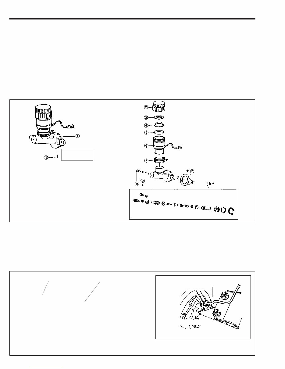
HOW TO USE THIS MANUAL CONTENTS OF EXPLANATION 1. Schematic Diagram of Components (1) The schematic diagram of components that appears at the beginning of each section describes the nomenclature and installed conditions of each component. Furthermore the tightening torque is posted in the figure. (2) Those parts whose reuse is not permitted bear a “★” mark for an identification purpose. Be certain to replace these parts with new ones during the assembly. (3) During the assembly, be sure to apply grease to those parts indicated by the mark in the figure. GI–4 (Example) 2. Servicing Procedure (1) In principle, the servicing procedure is described in the following sequence given below: Removal → Inspection → Installation, and Disassembly → Inspection → Assembly. (2) The explanation covers detailed servicing methods, specifications and notes. (3) The main point of each item explains the servicing section and servicing procedure, using illustrations. (Example) 3. Brake tube installation (1) Install the brake tube to the wheel cylinder temporarily by hands. (2) Tighten the brake tube to the wheel cylinder, using the following SST. SST: 09751-36011-000 What to do and where 09751-36011-000 JGI00003-00001 JGI00004-00002 T : Tightening torque Unit : N·m (kgf-m) ★ : Non-reusable parts What to do How to do it q Brake master cylinder Ay w Reservoir tank fill cap e Reservoir tank cap spacer r Reservoir tank diaphragm t Switch operating float y Master cylinder reservoir tank S/A u Clamp i Set bolt o Gasket !0 Gasket !1 Master cylinder repair kit T : 11.80 - 17.7 (1.2 - 1.8) Downloaded from www.Manualslib.com manuals search engine
(4) The inspection in this manual describes only checking operation. Therefore, if you find any malfunc- tion, replace any defective parts with new ones. 3. SST For those operations which require the use of any SST, the SST numbers concerned are given in bold letters. 4. Service Specifications Service specifications are indicated in bold letters or enclosed by heavy lines. Be certain to confirm the specifications concerned. 5. Tightening Torque For those operations which require the control of tightening torque, the relevant tightening torque is given in bold letters. Be certain to confirm the tightening torque concerned. 6. Definitions of Terms Specified Value …… A value which represents the allowable range during the inspection and adjustment. Limit ………………… A maximum or a minimum limit which the value should not exceed or fall below. GI–5 JGI00005-00000 Downloaded from www.Manualslib.com manuals search engine
ABBREVIATION CODES The abbreviation codes that appear in this workshop manual stand for the following, respectively. GI–6 The abbreviation codes that appear in the figure stand for the following, respectively. JGI00006-00000 JGI00007-00000 Abbreviation code Original word Meaning A/C Air Conditioner Refers to air conditioner. A/T, AT Automatic Transmission Refers to automatic transmission A/Y or Ay Assembly API American Petroleum Institute The standards set forth by the American Petroleum Institute (abbreviated as API Classification) have been employed to evaluate and classify properties of various oils. Engine oils for gasoline engines are classified as SD, SE, SF and so on, whereas engine oils for diesel engines are classified as CC, CD and so on. In instances where fitting becomes too loose due to wear resulting from use for a long period of time or due to frequent removal/installation operations, if the fitting part (e.g. piston) is replaced with a part having larger dimensions, the other mating part may be put into use again. “Oversized” parts denote those parts having larger dimensions compared with the standard parts. For example, automotive oils are designated as SAE so and so number. These designation numbers have been set forth by the Society of Automotive Engineers in the United States of America (SAE). The larger the SAE number, the higher the oil viscosity. Conversely, the smaller the SAE number, the lower the oil viscosity. Refers to a component comprising more than two single parts which are welded, staked, or studded to each other to form a single component. When referring to automotive parts, “standard” represents those parts which have been installed originally by the manufacturer and which have standard dimensions. Refers to an assembled component comprising more than two single parts or sub-assembly parts. Radio which incorporates variable capacitance, etc. which varies the value according to an applied voltage or current. In the same manner as with the “oversized” parts, if fitting part (e.g. bush and bearing) is replaced with a part having smaller bore dimensions, the other mating part may be put into use again. “Under sized” parts denote those parts having smaller dimensions compared with standard parts. ECU Electronic Control Unit Refers to electronic control unit. EFI Electronic Fuel Injection Refers to electronic fuel injection. F/L Fusible Link Refers to fusible link. L.H.D. Left-Hand Drive Left-hand drive vehicle. LH Left Hand Refers to left side. M/T, MT Manual Transmission Refers to manual transmission. MP Multipurpose Means that the following item has multi-purposes. O/S Oversize PR Ply Rating Represents strength of tires. The larger the ply rating number, the stronger the tire strength. R.H.D. Right-Hand Drive Right hand drive vehicle RH Right Hand Refers to right side. S/A Sub-Assembly SAE Society of Automotive Engineers SST Special Service Tool Refers to a tool designed for a specific purpose. STD Standard T Torque Refers to tightening torque. U/S Under Size VSV Vacuum Switching Valve Refers to vacuum switching valve. W/ With Denotes that the following part is attached. ETR Electronic Tuning Radio Bolt Nut Screw Washer B N S W Downloaded from www.Manualslib.com manuals search engine
GENERAL SERVICE INSTRUCTION 1. Use fender covers, seat covers and floor sheets so that the vehicle may not get dirty or be scratched. 2. Jacking up (1) When only the front section or rear section of the vehicle is jacked up, be sure to place chocks at the wheels so as to insure safe operations. (2) When the vehicle has been jacked up, be sure to support the vehicle at the specified section using safety stands. (See page GI–9) 3. Handling instructions related to battery. (1) Before you start performing the electrical works, make certain to disconnect the battery ground cable terminal from the negative (–) terminal of the battery. NOTE: • Before disconnecting the battery ground cable terminal from the negative (–) terminal of the battery, be sure to read out the diagnosis code of the EFI, Airbag and immobilizer system etc., if the vehicle is equipped with such systems, when necessary. • After reconnecting the battery ground cable terminal to the negative terminal of the battery, be sure to reset the watch or radio, if the vehicle is equipped with such equipment. (2) When it becomes necessary to disconnect the battery power supply for the purpose of carrying out checks or repairs, always disconnect the battery ground cable terminal from the negative terminal of the battery first. (3) To avoid damaging battery plates, after the terminal nut has been loosened, pull out the battery ground cable terminal straight upward, rather than turning or prying the terminal. NOTE: • Be sure to employ a battery terminal puller (commercially available) to remove the battery ground cable terminal from the negative terminal of the battery, if encountered any difficulty. (4) Clean the battery terminal posts or battery ground terminals, using a cloth. Never use a file or other adhesive agents. (5) When connecting the battery ground cable terminal to the battery, first the battery ground cable ter- minal should be fitted onto the battery post with the attaching nut in a loose state. Then, tighten the nut. Never tap the terminal onto the battery post, using a hammer or spanner wrench or the like. (6) As for the cover at the positive (+) terminal side, be sure to install it at the correct position. 4. Repairs of fuel system (1) The EFI equipped vehicles employ a high fuel pressure. Therefore, the following notes should be observed. q Be sure to prevent the fuel from splashing with a cloth or the like, when the union bolt or other connected section of the fuel line is loosened or slackened. (2) When connecting/disconnecting the fuel line. q Tighten each connecting section to the specified torque. w Attach new specified clips to each connecting section. e Be certain to place a suitable container or a cloth, etc. under the connected section of the fuel line before disconnecting the fuel line. r Before the fuel line is disconnected, be sure to release the inner pressure of the fuel tank by detaching the fuel filler cap. t Be sure to follow the instruction mentioned in the main text when disconnect or connect the quick type connectors. (3) Never work near open flames. 5. For increased work efficiency and improved accuracy, be sure to utilize SSTs (Special Service Tools) ef- fectively. GI–7 JGI00008-00000 Downloaded from www.Manualslib.com manuals search engine
HANDLING INSTRUCTIONS ON CATALYTIC CONVERTER WARNING: • When a great amount of unburnt gas is admitted into the catalytic converter, overheating is prone to occur, resulting in a fire hazard. To avoid such trouble in advance, be certain to observe the following precautions. Also, be sure to explain such precautions to your customers. 1. Use only unleaded gasoline. 2. Avoid idling the engine for a prolonged length of time. Do not run the engine continuously at idle speed for more than 20 minutes. WARNING: • Immediately check and repair the vehicle if the fast idle speed or idle speed is unstable or the system exhibits malfunction. Failure to observe this warning may result in a fire hazard. 3. Be sure to observe the following points when performing the spark jump tests. (1) The spark jump test must be limited to cases where such test is absolutely necessary. Also, be sure to finish the test in the shortest possible time. (2) Be sure to shut off the fuel supply when performing the spark jump test in advance. 4. Do not run the engine when the fuel tank becomes nearly empty. Failure to observe this caution will cause misfiring. Also, it will apply excessive load to the catalytic con- verter, even leading to catalyst damage. 5. Do not dispose of the waste catalyst along with parts contaminated with gasoline or oil. GI–8 JGI0009-00000 Downloaded from www.Manualslib.com manuals search engine
The Daihatsu Terios J100 1997 Factory Service Repair Manual is a comprehensive resource for repairing and adjusting the Daihatsu Terios J100 1997. It serves as a valuable reference for both professional mechanics and DIY enthusiasts. The manual provides detailed explanations for installation, removal, disassembly, assembly, repair, and check procedures, presented in a clear and sequential manner.
This manual is known by various names, including Daihatsu Terios J100 1997 service manual, repair manual, workshop manual, and shop manual. It is important to note that all these names refer to the same manual.
Upon purchase, immediate access to the manual is provided, enabling users to efficiently carry out their tasks.
The manual is organized into chapters, each covering specific aspects of the Daihatsu Terios J100 1997. The manual index outlines the following chapters:
General Information
Maintenance
Engine control
Engine mechanical
EFI system
Lubrication system
Cooling system
Ignition system
Starting system
Charging system
Clutch
Manual transmission
Automatic transmission
Transmission/transfer
Propeller shaft
Front axle & suspension
Rear axle & suspension
Brake
Steering
Body
Body electrical
Harness/wiring diagram
Each chapter is further divided into sections, with each section containing sub-sections. The titles of the sub-sections are presented in smaller print than the section titles. Additionally, exploded diagrams are included at the beginning of each removal and disassembly section to aid in part identification and procedure clarification.
The manual is available in PDF format, allowing users to conveniently print specific pages or the entire manual as needed.