

2002-2012 Daihatsu Copen Workshop Repair Service Manual BEST
What's Included?
Fast Download Speeds
Online & Offline Access
Access PDF Contents & Bookmarks
Full Search Facility
Print one or all pages of your manual
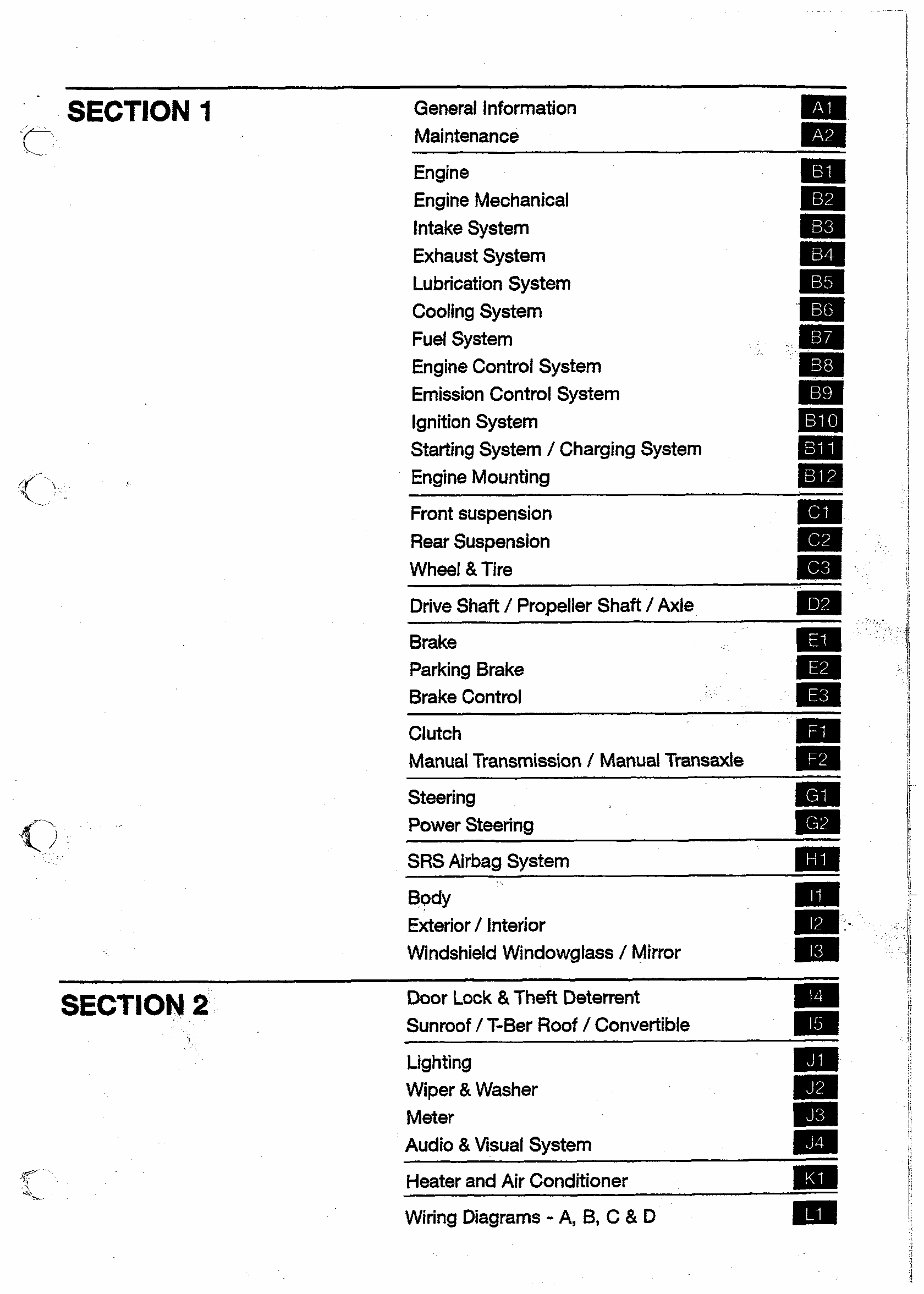
SECTION I General information
Maintenance
PI
i m
Engine
Engine Mechanical
rn
Em
Intake System
Exhaust System
lira
mm
Lubrication System rn
Cooling System Ea
Fuel System rn
Engine Control System rn
Emission Control System Im
Ignition System
Starting System / Charging System
Ea
BlEl
Engine Mounting ma
Front suspension
Rear Suspension
w
Wheel & Tire
m
mm
Drive Shaft / Propeller Shaft / Axle
rn
Brake
Parking Brake
m
Brake Control
rn
m
Clutch m
Manual Transmission / Manual Transaxle m
Steering
Power Steering
Em
Em
SRS Airbag System m
Body am
Exterior / Interior
Windshield Windowglass / Mirror
aa-
IB
SECTION 2
Door Lock & Theft Deterrent
Sunmof / T-Ber Roof /Convertible
mI
-- -
Lighting
Wiper & Washer
rn
Meter
ma
Audio & Visual System
ma
m
Heater and Air Conditioner mI
Wiring Diagrams - A, B, C & D
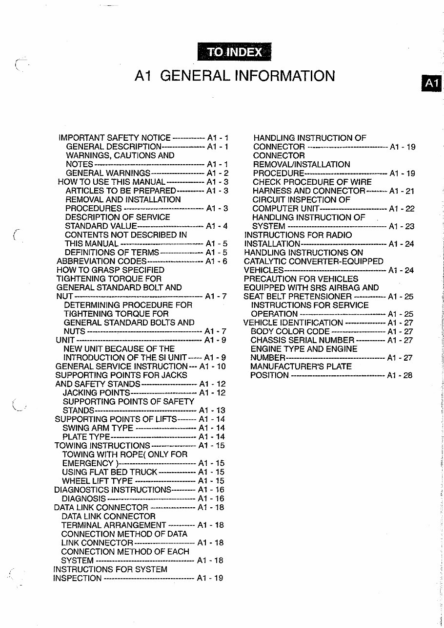
A1 GENERAL INFORMATION
IMPORTANT SAFETY NOTICE ------------ A1 - 1
GENERAL DESCRIPTION--------------- A1 - 1
WARNINGS, CAUTIONS AND
NOTES -------------------------------------
A1 - 1
GENERAL WARNINGS .................... A1 - 2
HOW TO USE THIS MANUAL------------- A1 - 3
ARTICLES TO BE PREPARED--------- A1 - 3
REMOVAL AND INSTALLATION
PROCEDURES A1 - 3
DESCRIPTION OF SERVICE
STANDARD VALUE Af - 4
CONTENTS NOT DESCRIBED IN
THIS MANUAL A1 - 5
DEFINITIONS OF TERMS ---------------- A1 - 5
ABBREVlATlON CODES -------------------- A1 - 6
HOW TO GRASP SPECIFIED
TIGHTENING TORQUE FOR
GENERAL STANDARD BOLT AND
NUT A1 - 7
DETERMINING PROCEDURE FOR
TIGHTENING TORQUE FOR
GENERAL STANDARD BOLTS AND
NUTS A1 - 7
UNIT A1 - 9
NEW UNIT BECAUSE OF THE
INTRODUCTION OF THE SI UNIT----- A1 - 9
GENERAL SERVICE INSTRUCTION --- A1 - 10
SUPPORTING POINTS FOR JACKS
AND SAFETY STANDS A1 - 12
JACKING POINTS A1 - 12
(.-
SUPPORTING POINTS OF SAFETY
STANDS A1 - 13
SUPPORTING POINTS OF LIFTS-------A1 - 14
SWING ARM TYPE ....................... A1 - 14
PLATE TYPE A1 - 14
TOWING INSTRUCTIONS---------------- A1 - 15
TOWING WlTH ROPE( ONLY FOR
EMERGENCY ) A1 - 15
USING FLAT BED TRUCK--------------A1 - 15
WHEEL LIFT TYPE A1 - 15
DIAGNOSTICS INSTRUCTIONS--------- A1 - 16
DIAGNOSIS A1 - 16
DATA LlNK CONNECTOR ----------------- A1 - 18
DATA LlNK CONNECTOR
TERMINAL ARRANGEMENT ---------- A1 - 18
CONNECTION METHOD OF DATA
LINK CONNECTOR ....................... A1 - 18
CONNECTION METHOD OF EACH
SYSTEM ..................................... A1 - 18
INSTRUCTIONS FOR SYSTEM
lNSPECTlON .................................. A1 - 19
HANDLING INSTRUCTION OF
CONNECTOR .............................. A1 - 1 9
CONNECTOR
REMOVAUINSTALLATION
PROCEDURE A1 - 19
CHECK PROCEDURE OF WIRE
HARNESS AND CONNECTOR--------A1 - 21
CIRCUIT INSPECTION OF
COMPUTER UNIT A1 - 22
HANDLING INSTRUCTION OF
SYSTEM ..................................... A1 - 23
INSTRUCTIONS FOR RADIO
INSTALLATION ------------------------. A1 - 24
HANDLING INSTRUCTIONSON
CATALYTIC CONVERTER-EQUIPPED
VEHICLES A1 - 24
PRECAUTION FOR VEHICLES
EQUIPPED WlTH SRS AIRBAG AND
SEAT BELT PRETENSIONER A1 - 25
INSTRUCTIONSFOR SERVICE
OPERATION A1 - 25
VEHICLE IDENTIFICATION --------------- A1 - 27
BODY COLOR CODE A1 - 27
CHASSIS SERIAL NUMBER A1 - 27
ENGINE TYPE AND ENGINE
NUMBER A1 - 27
MANUFACTURER'S PLATE
POS~TION A1 - 28
A1 -1
-
, .
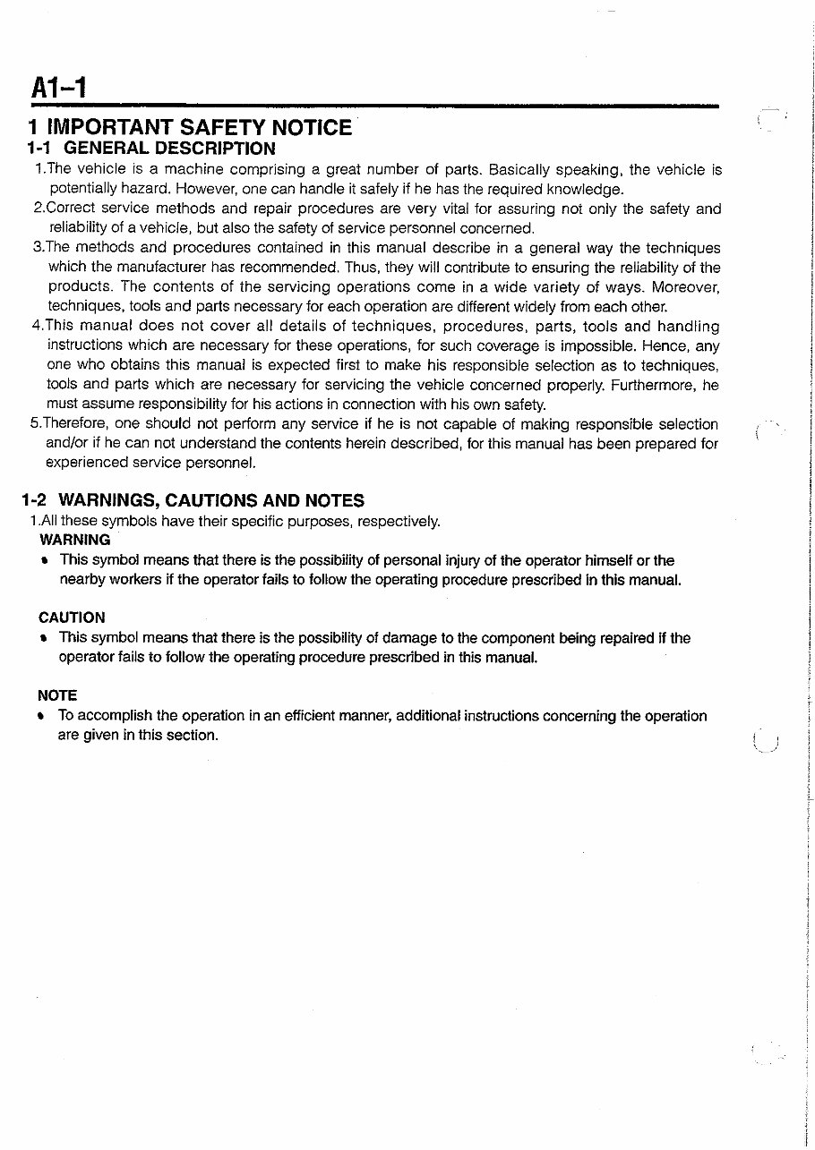
1 IMPORTANT SAFETY NOTICE
1-1 GENERAL DESCRIPTION
1.The vehicle is a machine comprising a great number of parts. Basically speaking, the vehicle is
potentially hazard. However, one can handle it safely if he has the required knowledge.
2.Correct service methods and repair procedures are very vital for assuring not only the safety and
reliability of a vehicle, but also the safety of service personnel concerned.
3.The methods and procedures contained in this manual describe in a general way the techniques
which the manufacturer has recommended. Thus, they will contribute to ensuring the reliability of the
products. The contents of the servicing operations come in a wide variety of ways. Moreover,
techniques, tools and parts necessary for each operation are different widely from each other.
4.This manual does not cover all details of techniques, procedures, parts, tools and handling
instructions which are necessary for these operations, for such coverage is impossible. Hence, any
one who obtains this manual is expected first to make his responsible selection as to techniques,
tools and parts which are necessary for servicing the vehicle concerned properly. Furthermore, he
must assume responsibility for his actions in connection with his own safety.
S.Therefore, one should not perform any service if he is not capable of making responsible selection
and/or if he can not understand the contents herein described, for this manual has been prepared for
i ~
experienced service personnel.
1-2 WARNINGS, CAUTIONS AND NOTES
1.All these symbols have their specific purposes, respectively.
WARNING
r This symbol means that there is the possibility of personal injury of the operator himself or the
nearby workers if the operator fails to follow the operating procedure prescribed in this manual.
CAUTION
r This symbol means that there is the possibility of damage to the component being repaired if the
operator fails to follow the operating procedure prescribed in this manual.
NOTE
r To accomplish the operation in an efficient manner, additional instructions concerning the operation
are given in this section. i I
: 1
,.-_,
-
A1 -2
!
1-3 GENERAL WARNINGS
1-3-1 WARNING OVER THE WHOLE SERVICE OPERATIONS
1 .Always wear safety glasses for eye protection.
2.Use safety stands whenever a procedure requires you to be under the vehicle.
3.Be sure that the ignition switch is always in the OFF position, unless otherwise required by the
procedure.
4.Set the oarkina brake when workina on the vehicle.
- -
5.0perate the engine only in a well-ventilated area to avoid the danger of carbon monoxide.
6.Keep yourself and your clothing away from moving parts, when the engine is running, especially from
the fan and belts.
7.To prevent serious burns, avoid contact with hot metal parts such as the radiator, exhaust manifold,
tail pipe, catalytic converter and muffler.
8.Do not smoke while working on a vehicle.
9.To avoid injury, always remove rings, watches, loose hanging jewelry, and loose clothing before
beginning to work on a vehicle.
10.Keep hands and other objects clear of the radiator fan blades! The electric cooling fan is mounted
on the radiator and can start to operate anytime by a rise in coolant temperature or turning ON of the
air conditioner switch in the case of vehicles equipped with an air conditioner. The electric cooling
fan is also mounted on the condenser for air conditioner and starts to operate anytime when the air
conditioner switch is turned ON. For this reason care should be taken to ensure that the electric
cooling fan motor is completely disconnected when working under the hood.
2 HOW TO USE THIS MANUAL
2-1 ARTICLES TO BE PREPARED
When SST, tool, measuring instrument, a sort of fat and oil to be prepared before operation are
necessary, those are described by compiling in the table as preparation tools at the beginning of each
item.
However, the general tools, jacks, fixtures as considered being equipped aiways at the service shop are
usually omitted.
2-2 REMOVAL AND INSTALLATION PROCEDURES
1.Block diagrams are posted so as to show the installed state of each part.
2.The application of a sort of fat and oil and sealer are instructed in the figure with arrow. And the
indication of a tightening torque and non-reusable parts are also described. The explanation of
each code is posted below the block diagram concerned.
3.The removal and installation (disassembling and assembling ) procedure list is shown just beneath of
components figure.
The removal (disassembling) procedure, the installation (assembling) procedure and parts name are
described in the sequence from left side of list. And the alphabet written before a part name links
with alphabet in the figure.
4 . h principle, reverse the removal (or disassembly) procedure to install (or assemble) the parts.
NOTE
Only in cases where the installation (or assembly) can not be carried out by reversing the removal
(or disassembly) procedure, the installation (or assembly) procedure is provided.
5 . h cases where a special procedure is required for the operation, a marking "VA" is provided in front
of the removal (or disassembly) procedure. Furthermore, explanation is given in the "Main points of
Removal (Disassembly)" or the "Main points of Installation (Assembly)."
The marking shows that there are the "Main points of Removal (Disassembly)." whereas "A"
shows that there are the "Main points of lnstallation (Assembly).''
I
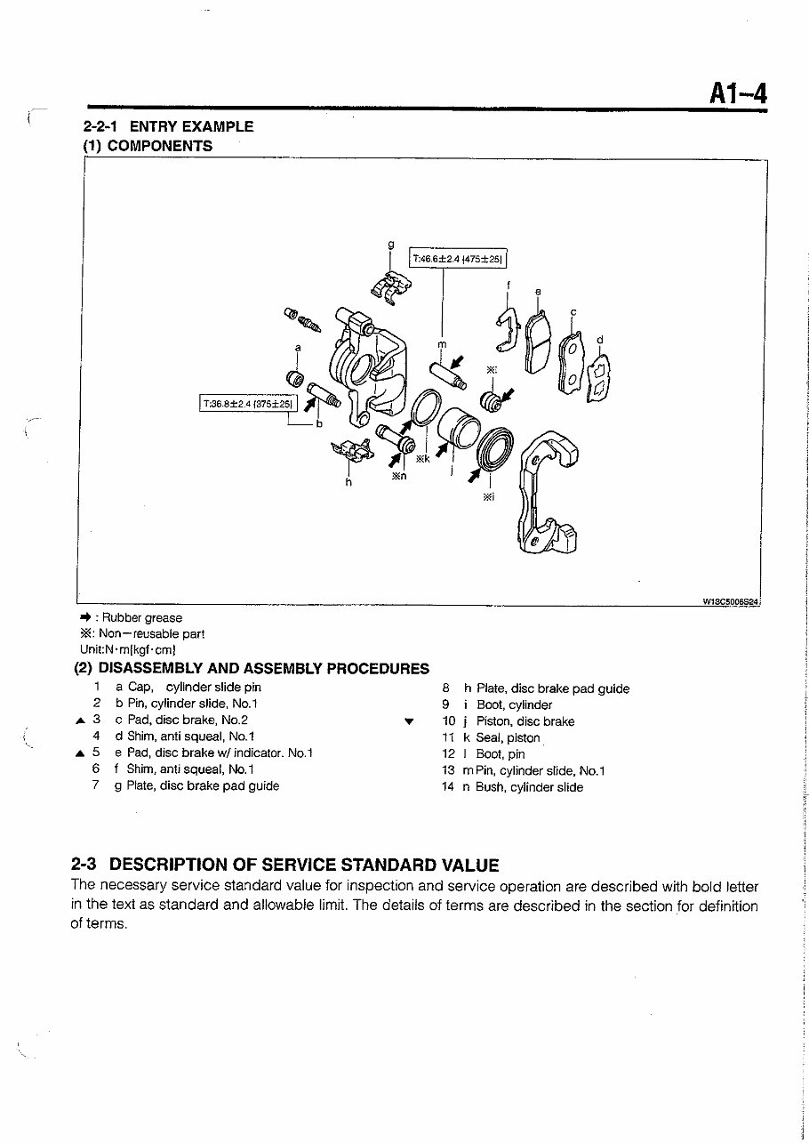
2-2-1 ENTRY EXAMPLE
) COMPONENTS
+ : Rubber grease
%: Non-reusable part
Unit:Nm(kgf.cm]
(2) DISASSEMBLY AND ASSEMBLY PROCEDURES
1 a Cap, cylinder slide pin
8 h Plate, disc brake pad guide
2 b Pin, cylinder slide. No.1
9 i Boot, cylinder
A 3 c Pad, disc brake, No2
r 10 j Piston, disc brake
\.
4 d Shim, anti squeal, No.1 11 k Seal, piston
A 5 e Pad, disc brake w/ indicator. No.? 12 1 Boot, pin
6 f Shim, anti squeal, No.1
13 rnPin, cylinder slide, No.1
7
g Plate, disc brake pad guide
14 n Bush, cylinder slide
2-3 DESCRIPTION OF SERVICE STANDARD VALUE
The necessary service standard value for inspection and service operation are described with bold letter
in the text as standard and allowable limit. The details of terms are described in the section for definition
of terms.
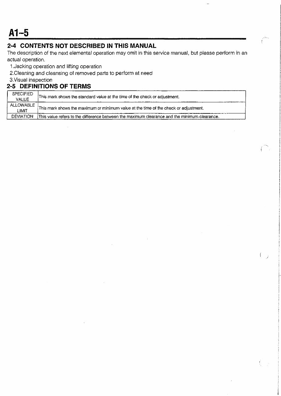
2-4 CONTENTS NOT DESCRIBED IN THIS MANUAL
The description of the next elemental operation may omit in this service manual, but please perform in an
actual operation.
1.Jacking operation and lifting operation
2.Cleaning and cleansing of removed parts to perform at need
3.Visual inspection
2-5 DEFINITIONS OF TERMS
I
LtWt, 4
I
DEVIATION Th~s vaLe refers to lne d~flerence be!ween tne maxlmm clearance ano the m i n i m ~ ~ . clearance
VALUE
This mark shows the standard value a! the time of the check or adjustment.
This mark shows the maximum or minimum value at the time of the check or adjustment.
t
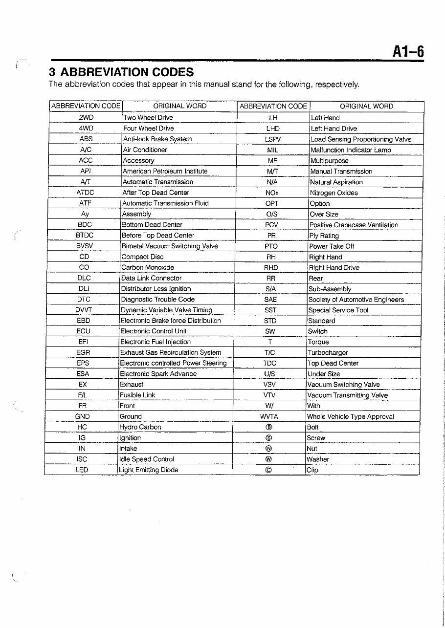
3 ABBREVIATION CODES
The abbreviation codes that appear in this manual stand for the following, respectively.
I ABBREVIATION CODE I ORIGINAL WORD I ABBREVIATION CODE I ORIGINAL WORD I
FR
GND
HC
IG
IN
ISC
LED
Front
Ground
Hydro Carbon
Ignition
Intake
Idle Speed Control
Light Emitting Diode
W/
WVTA
@
0
0
@
0
With
Whole Vehicle Type Approval
Bolt
Screw
Nut
Washer
Clip
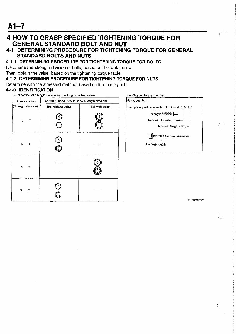
4 HOW TO GRASP SPECIFIED TIGHTENING TORQUE FOR
GENERAL STANDARD BOLT AND NUT
4-1 DETERMINING PROCEDURE FOR TIGHTENING TORQUE FOR GENERAL
STANDARD BOLTS AND NUTS
4-1-1 DETERMINING PROCEDURE FOR TIGHTENING TORQUE FOR BOLTS
Determine the strength division of bolts, based on the table below.
Then, obtain the value, based on the tightening torque table.
4-1-2 DETERMINING PROCEDURE FOR TIGHTENING TORQUE FOR NUTS
Determine with the aforesaid method, based on the mating bolt.
4-1 -3 IDENTIFICATION
Identification of strenglh division by checkhg bolts themselves
Identification by part number
Hexagonal bolt
Exampleofpartnumber9 1111-4 0620
,saGqJ JJ
Nominaldiameter (mm)
Nominal length (mm)
f Nominal diameter
t----i
Nominal length
Classification
(Strength division)
4 T
5 T
Shape of head (how to know strength division)
Bolt without collar
@
0
@
0
Bolt with collar
@
0
-
You're Reading a Preview
What's Included?
Fast Download Speeds
Online & Offline Access
Access PDF Contents & Bookmarks
Full Search Facility
Print one or all pages of your manual
$31.99
Viewed 46 Times Today


Secure transaction
What's Included?
Fast Download Speeds
Online & Offline Access
Access PDF Contents & Bookmarks
Full Search Facility
Print one or all pages of your manual
$31.99
This Workshop Repair Service Manual for the 2002-2012 Daihatsu Copen is a comprehensive guide for all your vehicle repair, maintenance, rebuild, refurbish, and restoration needs. It covers all diagnostic and repair procedures in great detail, making it an essential resource for both professional technicians and DIY enthusiasts.
Key features of this manual include:
- Complete coverage of all repair procedures from A-Z
- High-quality photos, illustrations, and diagrams
- Compatibility with all versions of Windows, Mac, and Linux
The manual includes detailed information on the following:
- General Information
- Engine (mechanical, lubrication system, cooling system, control system, fuel system, exhaust system)
- Transmission/Transaxle (clutch, manual transaxle, automatic transaxle)
- Driveline/Axle (front axle, rear axle)
- Suspension (front suspension, rear suspension, road wheels & tires)
- Brakes (brake system, parking brake system, brake control system)
- Steering (power steering system, steering system)
- Restraints (seat belts, supplemental restraint system)
- Body (lock & security system, glass, window system & mirrors, roof, exterior & interior, instrumental panel, seat)
- Air Conditioner (air conditioner system)
- Electrical (wiring diagrams, starting & charging system, lighting system, driver information system, wiper, washer & horn, body control system, lan system, audio visual, navigation & telephone system, auto cruise control system, power supply, ground & circuit elements)
- Maintenance
- Alphabetical Index
This manual is a valuable resource for anyone looking to effectively repair and maintain their 2002-2012 Daihatsu Copen. It provides in-depth information and guidance, ensuring that all repair procedures can be easily understood and implemented.


