Chapter 3 Cooling, heating and ventilation systems Contents Air conditioning compressor (auxiliary) drivebelt - checking and renewal See Chapter 1 Air conditioning system - general information and precautions .... 11 Air conditioning system components - removal and refitting 12 Air conditioning system refrigerant check See Chapter 1 Antifreeze mixture See Chapter 1 Coolant level check See Chapter 1 Coolant pump - removal and refitting 7 Cooling system - draining See Chapter 1 Cooling system - filling See Chapter 1 Cooling system - flushing See Chapter 1 Degrees of difficulty Cooling system electrical switches and sensors - testing, removal and refitting 6 Cooling system hoses - disconnection and renewal 2 Electric cooling fan(s) - testing, removal and refitting 5 General information and precautions 1 Heating and ventilation system - general information 8 Heater/ventilation components - removal and refitting 9 Heater vents - removal and refitting 10 Radiator - removal, inspection and refitting 3 Thermostat - removal, testing and refitting 4 Easy , suitable for novice with little experience Fairly easy, suitable for beginner with some experience Fairly difficult, suitable for competent DIY mechanic Difficult, suitable for experienced DIY mechanic Very difficult, suitable for expert DIY or professional Specifications General Maximum system pressure 1.4 bars Thermostat Opening temperatures: Starts to open 89°C Fully-open 101°C Electric cooling fan(s) Cooling fan(s) cut in: Single-speed cooling fan: 1998 cc 8-valve models 95°C All other models 97°C Twin-speed cooling fan(s):* Slow speed 97°C Fast speed 101°C Cooling fan(s) cut out: Single-speed cooling fan: 1998 cc 8-valve models 86°C All other models 92°C Twin-speed cooling fan(s):* Slow speed -. 92°C Fast speed 96°C 'Twin-speed cooling fans are fitted to all models with air conditioning, and to models supplied to countries with a hot climate. Torque wrench settings Nm ibf ft Coolant pump bolts: 1124 cc and 1360 cc models: Lower bolt 7 5 Upper bolt 16 12 1580 cc and larger-engined models 15 11 Temperature switches/sensors: Screwed into radiator 35 26 Screwed into cylinder head/coolant outlet housing 18 13
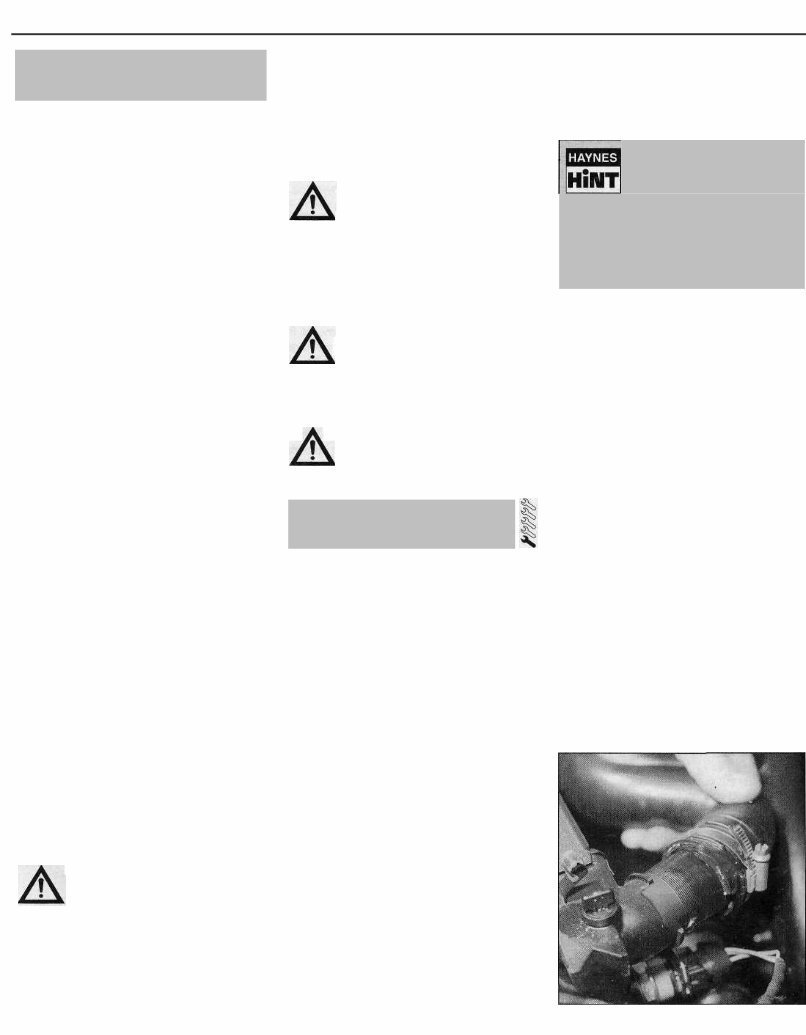
3•2 Cooling, heating and ventilation systems General information The cooling system is of pressurised type, comprising a coolant pump driven by the timing belt, an aluminium crossflow radiator with integral expansion tank, electric cooling fan(s), a thermostat, heater matrix, and all associated hoses and switches. The system functions as follows. Cold coolant in the bottom of the radiator passes through the bottom hose to the coolant pump, where it is pumped around the cylinder block and head passages, and through the oil cooler(s) (where fitted). After cooling the cylinder bores, combustion surfaces and valve seats, the coolant reaches the underside of the thermostat, which is initially closed. The coolant passes through the heater, and is returned via the cylinder block to the coolant pump. When the engine is cold, the coolant circulates only through the cylinder block, cylinder head, and heater. When the coolant reaches a predetermined temperature, the thermostat opens, and the coolant passes through the top hose to the radiator. As the coolant circulates through the radiator, it is cooled by the inrush of air when the car is in forward motion. The airflow is supplemented by the action of the electric cooling fan(s) when necessary. Upon reaching the bottom of the radiator, the coolant has now cooled, and the cycle is repeated. When the engine is at normal operating temperature, the coolant expands, and some of it is displaced into the expansion tank. Coolant collects in the tank, and is returned to the radiator when the system cools. On models with automatic transmission, a proportion of the coolant is recirculated from the bottom of the radiator through the transmission fluid cooler mounted on the transmission. On 16-valve models, the coolant is also passed through the engine oil cooler. The electric cooling fan(s) mounted in front of the radiator are controlled by a thermostatic switch. At a predetermined coolant temperature, the switch/sensor actuates the fan. Precautions Warning: Do not attempt to remove the expansion tank filler cap, or to disturb any part of the cooling system, while the engine is hot, as there is a high risk of scalding. If the expansion tank filler cap must be removed before the engine and radiator have fully cooled (even though this is not recommended), the pressure in the cooling system must first be relieved. Cover the cap with a thick layer of cloth, to avoid scalding, and slowly unscrew the filler cap until a hissing sound is heard. When the hissing has stopped, indicating that the pressure has reduced, slowly unscrew the filler cap until it can be removed; if more hissing sounds are heard, wait until they have stopped before unscrewing the cap completely. At all times, keep well away from the filler cap opening, and protect your hands. Warning: Do not allow antifreeze to come into contact with your skin, or with the painted surfaces of the vehicle. Rinse off spills immediately, with plenty of water. Never leave antifreeze lying around in an open container, or in a puddle in the driveway or on the garage floor. Children and pets are attracted by its sweet smell, but antifreeze can be fatal if ingested. Warning: If the engine is hot, the electric cooling fan may start rotating even if the engine is not running. Be careful to keep your hands, hair, and any loose clothing well clear when working in the engine compartment. Warning: Refer to Section 11 for precautions to be observed when working on models equipped with air conditioning. 2 Cooling system hoses - disconnection and renewal Note: Refer to the warnings given in Section 1 of this Chapter before proceeding. Hoses should only be disconnected once the engine has cooled sufficiently to avoid scalding. 1 If the checks described in Chapter 1 reveal a faulty hose, it must be renewed as follows. 2 First drain the cooling system (see Chap- ter 1). If the coolant is not due for renewal, it may be re-used, providing it is collected in a clean container. 3 To disconnect a hose, proceed as follows, according to the type of hose connection. Conventional hose connections - general instructions 4 On conventional connections, the clips used to secure the hoses in position may be either standard worm-drive clips or disposable crimped types. The crimped type of clip is not designed to be re-used and should be replaced with a worm drive type on reassembly. 5 To disconnect a hose, use a screwdriver to slacken or release the clips, then move them along the hose, clear of the relevant inlet/outlet. Carefully work the hose free (see illustration). The hoses can be removed with relative ease when new - on an older car, they may have stuck. 6 If a hose proves to be difficult to remove, try to release it by rotating its ends before attempting to free it. Gently prise the end of the hose with a blunt instrument (such as a flat-bladed screwdriver), but do not apply too much force, and take care not to damage the pipe stubs or hoses. Note in particular that the radiator inlet stub is fragile; do not use excessive force when attempting to remove the hose. If all else fails, cut the hose with a sharp knife, then slit H so that it can be peeled off in two pieces. Although this may prove expensive if the hose is otherwise undamaged, It is preferable to buying a new radiator. Check first, however, that a new hose is readily available. 7 When fitting a hose, first slide the clips onto the hose, then work the hose into position. If crimped-type clips were originally fitted, use standard worm-drive clips when refitting the hose. If the hose is stiff, use a little soapy water as a lubricant, or soften the hose by soaking it in hot water. Do not use oil or grease, which may attack the rubber. 8 Work the hose into position, checking that it is correctly routed, then slide each clip back along the hose until it passes over the flared end of the relevant inlet/outlet, before tightening the clip securely. 9 Refill the cooling system with reference to Chapter 1. 10 Check thoroughly for leaks as soon as possible after disturbing any part of the cooling system. Radiator bottom hose Removal 11 Turn the locking ring ("2") anti-clockwise until it contacts the stop ("1") (see illustration). 12 Press the connector away from the hose, to ensure that the two retaining lugs are free (see illustration). 13 Pull the hose, complete with the connector, from the radiator. 2.5 Disconnecting the radiator top hose 1 General information and precautions
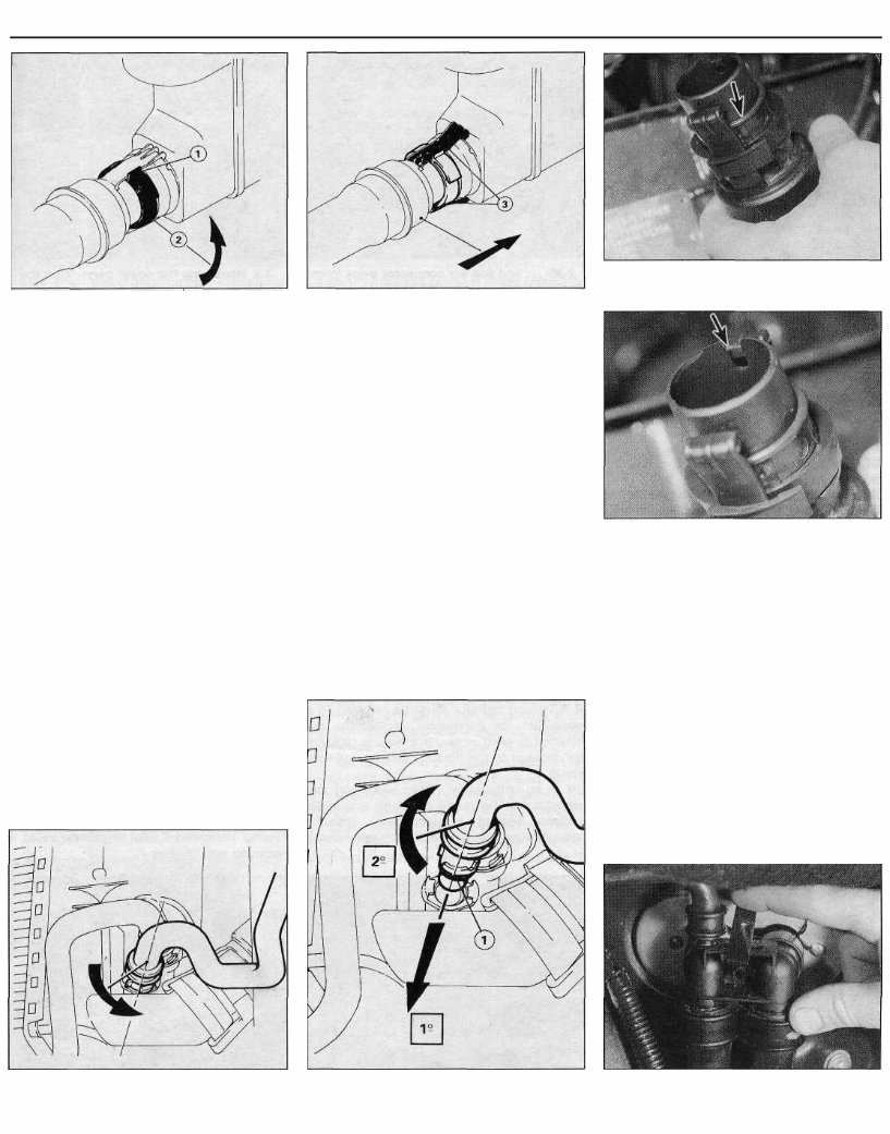
Cooling, heating and ventilation systems 3•3 2.11 To release the radiator bottom hose connection, turn the locking ring (2) until it contacts the stop (1) 14 Recover the O-ring from the connector, and discard it; a new one must be used on refitting. Refitting 15 Wipe the connector and the stub on the radiator thoroughly with a clean, lint-free cloth. 16 Fit a new O-ring to the male half of the connector, ensuring that it is correctly seated (see illustration). 17 Turn the locking ring clockwise until it clicks. 18 Offer the hose to the stub on the radiator, with the locating cut-out in the male part of the connector located at the bottom (see illustration). 19 Push the connector into the stub until both the retaining lugs click into position. Make sure that the O-ring is not trapped. 20 Pull the connector rearwards (away from the stub) to adjust the position of the retaining lugs if necessary. 21 Refill the cooling system with reference to Chapter 1. 22 Check thoroughly for leaks as soon as possible after disturbing any part of the cooling system. 2.12 Press the connector away from the hose, to ensure that the two retaining lugs (3) are free Radiator bypass hose connection Removal 23 The hose is secured by means of a bayonet-fit connector. 24 Turn the connector on the end of the hose anti-clockwise as far as it will go (see illustration). 25 Rock the connector back and forth to release it from the radiator outlet. Remove the O-ring, and discard it; a new must be used on refitting. Refitting 26 Wipe the connector and the stub on the radiator thoroughly with a clean, lint-free cloth. 27 Fit a new O-ring to the male half of the connector. 28 Offer the connector to the outlet on the radiator, and twist anti-clockwise to engage 2.16 On refitting, fit a new O-ring (arrowed) to the hose union 2.18 Offer the hose to the radiator, with the cut-out (arrowed) at the bottom the guide rails on the connector with the lugs on the radiator (see illustration). 29 Push the connector fully home to compress the O-ring. 30 Turn the connector clockwise as far as the stop. 31 Refill the cooling system with reference to Chapter 1. 32 Check thoroughly for leaks as soon as possible after disturbing any part of the cooling system. Heater matrix hose connections Removal 33 The two hoses are connected to the matrix by means of a single connector. 34 Prise the metal retaining clip from the top of the connector (see illustration). 2.24 To release the radiator bypass hose, turn the connector on the end of the hose anti-clockwise 2.28 On refitting, engage the guide rails (1) with the lugs on the radiator, then twist the hose end in a clockwise direction 2.34 Remove the metal clip from the top of the heater matrix connector on the engine compartment bulkhead . . .
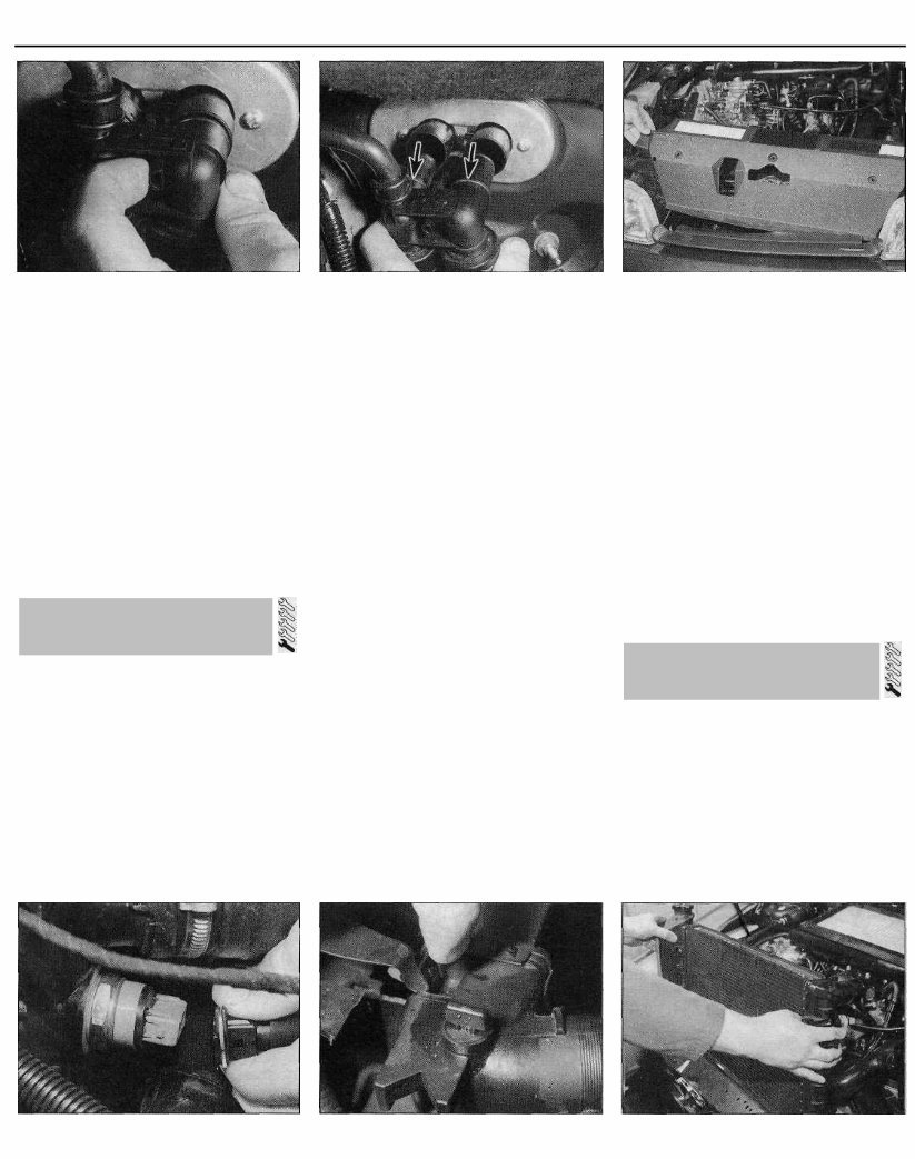
3•4 Cooling, heating and ventilation systems 2.35 . . . then release the plastic retaining 2.36 . . . and pull the connector away from 3.3 Removing the cover panel from the clip . . . the bulkhead - recover the O-rings (arrowed) radiator 35 Release the plastic retaining clip by pushing it towards the left-hand hose connection (see illustration). 36 Pull the connector assembly from the heater matrix. Recover the O-ring seals from the connector, and discard them; new ones should be used on refitting (see illustration). Refitting 37 Refitting is a reversal of the removal procedure, using new O-rings. 38 Refill the cooling system with reference to Chapter 1. 39 Check thoroughly for leaks as soon as possible after disturbing any part of the cooling system. 3 Radiator - removal, inspection and refitting Note: New sealing rings must be used when reconnecting the radiator lower hoses - see Section 2. If leakage is the reason for removing the radiator, bear in mind that minor leaks can often be cured using a radiator sealant with the radiator in situ. Removal 1 Disconnect the battery negative lead. 2 Drain the cooling system as described in Chapter 1. 3 Undo the three retaining screws, and remove the plastic cover panel from above the radiator (see illustration). 4 Disconnect the wiring plug from the cooling fan switch (where fitted) on the left-hand side of the radiator (see illustration). 5 Disconnect the radiator upper hose(s) (left- hand side), and the lower hoses (right-hand side), with reference to Section 2. 6 Depress the two retaining clips, located at the top ends of the radiator, then carefully lift the radiator from the vehicle. Note the locating lugs at the bottom of the radiator, which locate in the mounting rubbers in the lower body panel (see illustrations). Inspection 7 If the radiator has been removed due to suspected blockage, reverse-flush it as described in Chapter 1. Clean dirt and debris from the radiator fins, using an air line (in which case, wear eye protection) or a soft brush. Be careful, as the fins are sharp, and easily damaged. 8 If necessary, a radiator specialist can perform a "flow test" on the radiator, to establish whether an internal blockage exists. 9 A leaking radiator must be referred to a specialist for permanent repair. Do not attempt to weld or solder a leaking radiator, as damage to the plastic components may result. 10 In an emergency, minor leaks from the radiator can be cured by using a suitable radiator sealant, in accordance with its manufacturer's instructions, with the radiator in situ. 11 If the radiator is to be sent for repair or renewed, remove all hoses, and the cooling fan switch (where fitted). 12 Inspect the condition of the radiator mounting rubbers, and renew them if necessary. Refitting 13 Refitting is a reversal of removal, bearing in mind the following points: (a) Ensure that the lower lugs on the radiator are correctly engaged with the mounting rubbers in the body panel. (b) Reconnect the hoses with reference to Section 2, using new O-rings where applicable. (c) On completion, refill the cooling system as described in Chapter 1. Removal 1 Disconnect the battery negative lead. 2 Drain the cooling system as described in Chapter 1. 3 Where necessary, release any relevant wiring and hoses from the retaining clips, and position clear of the thermostat housing to improve access. On 1905 cc models, access is also improved if the air cleaner duct is removed (see Chapter 4). 3.4 Disconnecting the cooling fan switch wiring plug 3.6a Depress the retaining clips . . . 3.6b . . . and withdraw the radiator 4 Thermostat - removal, testing and refitting
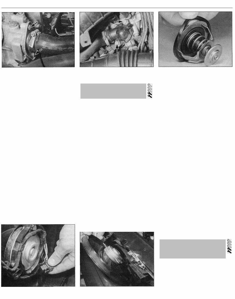
Cooling, heating and ventilation systems 3•5 4.4a Thermostat housing cover retaining bolts (arrowed) - 1360 cc models 4 Unscrew the retaining bolts, and carefully withdraw the thermostat housing cover to expose the thermostat. Take care not to strain the coolant hoses connected to the cover (see illustrations). 5 Lift the thermostat from the housing, and recover the sealing ring(s) (see illustration). Testing 6 A rough test of the thermostat may be made by suspending it with a piece of string in a container full of water. Heat the water to bring it to the boil - the thermostat must open by the time the water boils. If not, renew it. 7 If a thermometer is available, the precise opening temperature of the thermostat may be determined; compare with the figures given in the Specifications. The opening temperature is also marked on the thermostat. 8 A thermostat which fails to close as the water cools must also be renewed. Refitting 9 Refitting is a reversal of removal, bearing in mind the following points: (a) Examine the sealing ringfs) for signs of damage or deterioration, and if necessary, renew. (b) Ensure that the thermostat is fitted the correct way round, with the spring(s) facing into the housing. (cj On completion, refill the cooling system as described in Chapter 1. 4.4b Thermostat housing cover retaining bolts (arrowed) -1905 cc models 5 Electric cooling fan(s) - testing, removal and refitting Testing 1 Current supply to the cooling fan(s) is via the ignition switch (see Chapter 5) and a fuse (see Chapter 12). The circuit is completed by the cooling fan thermostatic switch, which (on most models) is mounted in the left-hand side of the radiator. On models with air conditioning, the cooling fans are controlled by the "Bitron" sensor - see Section 6. 2 If a fan does not appear to work, run the engine until normal operating temperature is reached, then allow it to idle. The fan should cut in within a few minutes (before the temperature gauge needle enters the red section, or before the coolant temperature warning light comes on). If not, switch off the ignition and disconnect the wiring plug from the cooling fan switch. Bridge the two contacts in the wiring plug using a length of spare wire, and switch on the ignition. If the fan now operates, the switch is probably faulty, and should be renewed. 3 If the fan still fails to operate, check that battery voltage is available at the feed wire to the switch; if not, then there is a fault in the feed wire (possibly due to a fault in the fan motor, or a blown fuse). If there is no problem with the feed, check that there is continuity between the switch earth terminal and a good 4.5 Removing the sealing ring from the thermostat flange earth point on the body; if not, then the earth connection is faulty, and must be re-made. 4 If the switch and the wiring are in good condition, the fault must lie in the motor itself. The motor can be checked by disconnecting it from the wiring loom, and connecting a 12-volt supply directly to it. Removal 5 Remove the radiator as described in Section 3. 6 Disconnect the wiring plug from the rear of the motor (see illustration). 7 On models with a plastic radiator shroud (both single- and twin-fan arrangements), unscrew the three motor retaining nuts, rotating the fan blades as necessary so that the bolts can be counterheld from the front as the nuts are unscrewed. Withdraw the motor assembly, complete with the fan, from the front of the vehicle (see illustration). 8 On models with a single cooling fan where the motor is secured to the body by a metal frame, undo the retaining bolts, then remove the motor and mounting frame from the vehicle. 9 If desired, the fan blades can be removed from the motor shaft, after its retaining screw or clip (as applicable) has been removed. 10 If the motor is faulty, the complete unit must be renewed, as no spares are available. Refitting 11 Refitting is a reversal of removal. Refit the radiator as described in Section 3. 6 Cooling system electrical switches and sensors - testing, removal and refitting 5.6 Disconnecting the wiring plug from a cooling fan 5.7 Withdrawing a cooling fan motor assembly - twin-fan arrangement Electric cooling fan thermostatic switch - models without air conditioning Testing 1 Testing of the switch is described in Section 5, as part of the electric cooling fan test procedure.
You're Reading a Preview
What's Included?
Lifetime Access
Fast Download Speeds
Offline Viewing
Access Contents & Bookmarks
Full Search Facility
Print one or all pages of your manual
$33.99
1991-1998 Citroen ZX 1905cc Hatchback Service & Repair Manual
This is the complete factory service repair manual for the Citroen ZX 1905cc Hatchback 1991-1998. This Service Manual has easy-to-read text sections with top quality diagrams and instructions. They are specifically written for the do-it-yourselfer as well as the experienced mechanic. With step by step instruction & highly detailed exploded pictures & diagrams to show you how to complete the required job correctly & efficiently. Using Citroen ZX 1905cc Hatchback 1991-1998 Service Repair Workshop Manual covers every single detail on your machine. Provides step-by-step instructions based on the complete disassembly of the machine. This Citroen ZX 1905cc Hatchback 1991-1998 repair manual is an inexpensive way to keep your vehicle working properly.
Models Covers:
Citroen ZX 1905cc Hatchback 1991-1998
Service Repair Manual Covers:
General information
Periodic maintenance
Engine
Fuel system and throttle body
Cooling and lubrication system
Chassis
Electrical system
Servicing information
Emission control information
Wiring diagram
... and more
This professional technical manual contains service, maintenance, and troubleshooting information for your Citroen ZX 1905cc Hatchback 1991-1998, covering All Models/Engines/Trim/Transmissions Types. This top quality Citroen ZX 1905cc Hatchback 1991-1998 Workshop Repair Service manual is COMPLETE and INTACT as should be without any MISSING/CORRUPT part or pages. It is the SAME manual used in the local service/repair shop. Citroen ZX 1905cc Hatchback 1991-1998 manual is guaranteed to be fully functional to save your precious time.
Immediate access! No waiting! You will have instant access to your manual! No shipping fee, No waiting nervously for the postal delivery, you can start doing your repairs right away! Buy now!
PRODUCT DETAILS:
Citroen ZX 1905cc Hatchback 1991-1998
File Format: PDF
Language: English
Printable: Without any restriction
Delivery: Link will appear on the checkout page after payment is complete.
Requirements: Adobe Reader
Buyers can pay for products via PayPal or Credit Card. We accept payments on behalf of our merchants and send payouts once per week. Click on the instant payment button to pay with your PayPal or credit card and you will receive the download link instantly.
Reviews
Q&A
Recently Viewed
5,521,897Happy Clients
2,594,462eManuals
1,120,453Trusted Sellers
15Years in Business
Price:
Actual Price:
1991-1998 Citroen ZX 1905cc Hatchback Service & Repair Manual



 Lifetime Access




