1965-1975 Citroen D Models Service & Repair Manual
What's Included?
Lifetime Access
Fast Download Speeds
Offline Viewing
Access Contents & Bookmarks
Full Search Facility
Print one or all pages of your manual
A I A DTAV I TECHNICAL ASSISTANCE) CHARACTERISTICS REPAIR MANUAL No814 VOLUME I ICL (D vehicles all types produced since September 1965)‘ ADJUSTMENTS CHECKS MARCH 1974
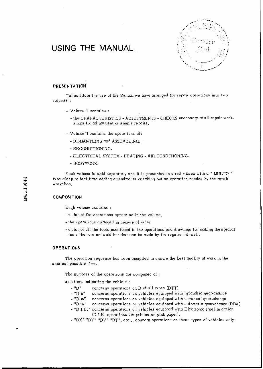
. USING THE MANUAL PRESENTATION To facilitate the use of the Manual we have arranged the repair operations into two volumes : - Volume 1 contains : - the CHARACTERISTICS - ADJUSTMENTS - CHECKS necessary atall repair work- shops for adjustment or simple repairs. - Volume II contains the operations of: - DISMANTLING and ASSEMBLING. - RECONDITIONING. - ELECTRICAL SYSTEM - HEATING - AIR CONDITIONING. - BODYWORK. Each volume is sold separately and it is presented in a red Fibrex with a ” MOLTO ” type clasp to facilitate adding amendments or taking out an operation needed by the repair workshop. COMPOSITION Each volume contains : - a list of the operations appearing in the volume. - the operations arranged in numerical order - a list of all the tools mentioned in the operations and drawings for making thespecial tools that are not sold but that can be made by the repairer himself. OPERATIONS The operation sequence has been compiled to ensure the best quality of work in the shortest possible time, The numbers of the operations are composed of : a) letters indicating the vehicle : - “D” concerns operations on D of all types (DTT) _ “D h” concerns operations on vehicles equipped with hylaudric gear-change _ “D m” concerns operations on vehicles equipped with a manual gear-change - “DbW” concerns operations on vehicles equipped with automatic gear-change (DBW) - “D.I.E.” concerns operations on vehicles equipped with Electronic Fuel Injection (D.I.E. -operations are printed oti pink paper). _ “DX” “Dy” “DV” “DT”, etc... concern operations on these types of vehicles only.
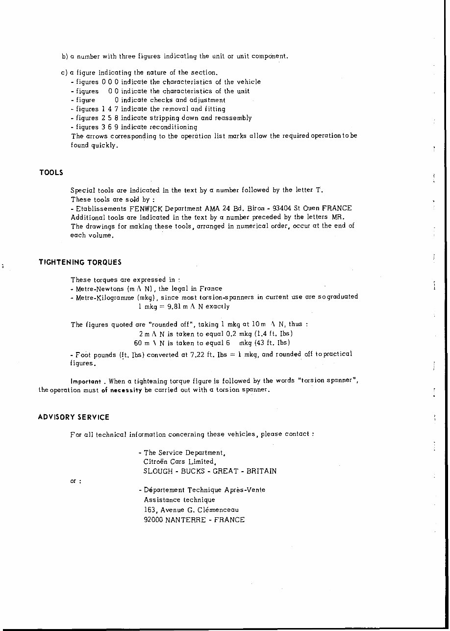
b) a number with three figures indicating the unit or unit component. c) a figure indicating the nature of the section. - figures 0 0 0 indicate the characteristics of the vehicle - figures 0 0 indicate the characteristics of the unit - figure 0 indicate checks and adjustment - figures 1 4 7 indicate the removal and fitting - figures 2 5 8 indicate stripping down and reassembly - figures 3 6 9 indicate reconditioning The arrows corresponding to the operation list marks allow the required operation tobe found quickly. TOOLS Special tools are indicated in the text by a number followed by the letter T. These tools are sold by : - Etablissements FENWICK Department AMA 24 Bd. Biron - 93404 St Ouen FRANCE Additional tools are indicated in the text by a number preceded by the letters MR. The drawings for making these tools, arranged in numerical order, occur at the end of each volume. : TIGHTENING TORQUES These torques are expressed in : - Metre-Newtons (m A N) , the legal in France - Metre-Kilogramme (mkg), since most torsion-spanners in current use are sograduated 1 mkg = 9.81 m A N exactly The figures quoted are “rounded off”, taking 1 mkg at 10m ~1 N, thus : 2 m A N is taken to equal 0.2 mkg (1.4 ft. Ibs) 60 m 1 N is taken to equal 6 mkg (43 ft. Ibs) - Foot pounds (ft. Ibs) converted at 7.22 ft. Ibs = 1 mkg, and rounded off topractical figures. Important . When a tightening torque figure is followed by the words “torsion spanner”, theoperation must of necessity be carried out with a torsion spanner. ADVISORY SERVICE For all technical information concerning these vehicles, please contact : - The Service Department, Citroen Cars Limited, SLOUGH - BUCKS - GREAT - BRITAIN or : - Dipartement Technique Apres-Vente Ass istance technique 163, Avenue G. Clirmenceau 92000 NANTERRE - FRANCE
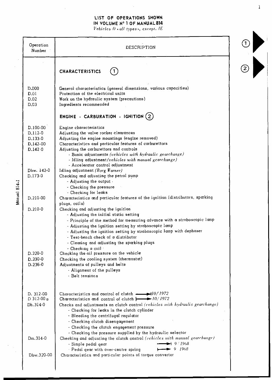
1 Operation Number DO00 D.O1 D.02 D.03 D.lOO-00 D.112-0 D.133-0 D.142-00 D.142-0 Dbw. 142-O D.173-0 D.210-00 D.210-0 D.220-0 D.2300 D.236-0 D. 312-00 D 312-OOa Dh.314-0 Dm.314-0 Dbw.320-00 LIST OF OPERATIONS SHOWN IN VOLUME No 1 OF MANUAL814 Vehicles D u all types a, except. IE DESCRIPTION CHARACTERISTICS 1 0 General characteristics (general dimensions, various capacities) Protection of the electrical units Work on the hydraulic system (precautions) Ingredients recommended ENGINE - CARBURATION - IGNITION @ Engine characteristics Adjusting the valve rocker clearances Adjusting the engine mountings (engine removed) Characteristics and particular features of carburettors Adjusting the carburettors and controls - Basic adjustments (vehicles with hydraulic gearchange) - Idling adjustment (vehicles with manual gearchange) - Accelerator control adjustment Idling adjustment (Borg Warner) Checking and adjusting the petrol pump - Adjusting the output - Checking the ,pressure - Checking for leaks Characteristics and particular features of the ignition (distributors, sparking plugs, coils) Checking and adjusting the ignition - Adjusting the initial static setting - Principle of the method for measuring advance with a stroboscopic lamp - Adjusting the ignition setting by stroboscopic lamp - Adjusting the ignition setting by stroboscopic lamp with dephaser - Test-bench check of a distributor - Cleaning and adjusting the sparking plugs - Checkrng a coil Checking the.oil pressure on the vehicle Checking the cooling system (thermostat) Adjustments of pulleys and belts - Alignment of the pulleys - Belt tensions Characteristics and control of clutch +10/1972 Characteristics and control of clutch i-*10/197-3 Checks and adjustments on clutch control (vehicles lclith hydraulic gearchange) - Checking for leaks in the clutch cylinder - Bleeding the centrifugal regulator - Checking clutoh disengagement - Checking the clutch engagement pressure - Checking the’pressure supplied by the hydraulic selector Checking and adjusting the clutch control (c)ehicles with manual gearchungr) - Simple pedal gear L-H 9 ‘1958 - Pedal gear with over-centre spring H 9 19hR Characteristics and particular points of torque converter 0 1 b’ 0 2 b
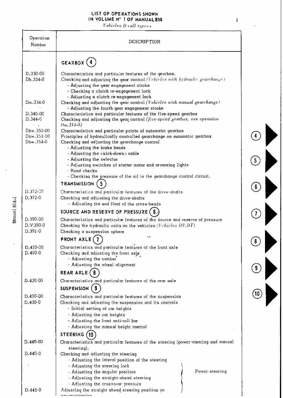
- Operation Number - D .330-00 D h.334-0 m.334-0 .340-00 .344-o bw .350-00 bw.354-00 bw.354-0 D. 0 ,372-X 372-O 390-00 ,v 390-O 391-o ,410-00 410-O D. D. D. Da D. D. D. D. D< D D 420-00 430-00 430-O ,44600 .440-o .445-o LIST OF OPERATIONS SHOWN IN VOLUME No 1 OF MANUAL814 I’ehicles U o a/L typc.s a 2 DESCRIPTION GEARBOX 4 0 Characteristics and particular features of the gearbox. Checking and adjusting the gear control (1 c,hiclcs tc,i//t /t~~tfrcttc/i(~ gi,urchntt,gr- I - Adjusting the gear engagement stroke - Checking a clutch re-engagement lock - Adjusting a clutch re-engagement lock Checking and adjusting the gear control (Vehicles with manual gearchange) - Adjusting the fourth gear engagement stroke Characteristics and particular features of the five-speed gearbox Checking and adjusting the gear control (fice-speed gearbox, see operatiott l)tt1.33 !-0) Characteristics and particular points of automatic gearbox Principles of hydraulically controlled gearchange on automatic gearbox Checking and adjusting the gearchange control - Adjusting the brake bands - Adjusting the ((kick-down)) cable - Adjusting the selector - Adjusting switches of starter motor and reversing lights - Road checks - Checkinq the pressure of the oil in the gearchange control circuit. T RANSMI SSION 0 5 Characteristics and particular features of the drive-shafts Checking and adjusting the drive-shafts - Adjusting the end float of the cross-heads SOURCE AND RESERVE OF PRESSURE 6r 0 Characteristics and particular features of the source and reserve of pressure Checking the hydraulic units on the vehicles (VvhicLes DV.131’) Checking a suspension sphere FRONT AXLE 7 0 4 Characteristics and particular feat&es of the front axle Checking and adjusting the front ax@.L - Adjusting the cambe; - Adjusting the wheel alignment REAR AXLE 8 0 Characteristics and particular features of the rear axle SUSPENSION @ Characteristics and particular features of the suspension Checking and adjusting the suspension and its controls - Initial setting of car heights - Adjusting the car heights - Adjusting the front anti-roll bar - Adjusting the manual height control STEERING 10 0 Characteristics and particular features of the steering (power-steering and manual steering). Checking and adjusting the steering - Adjusting the lateral position of the steering - Adjusting the steering lock - Adjusting the angular position I Power-steering - Adjusting the straight-ahead steering - Adjusting the crossover pressure Adjusting the straight ahead steering position on i -o...,,-,+n,,;n” Oh 4 OF 5 Ob 6 Oh 7 Oh 8 Oh 9
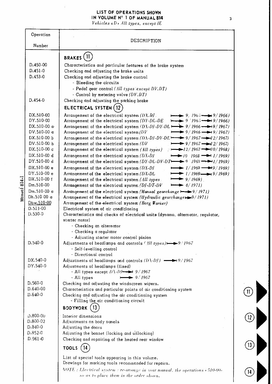
Operation Number D.450-00 D.451-0 D.453-0 D.454-0 DX.51 O-00 DY.SlO-00 DX.SlO-00 a. DV.SlO-00 a DX.SlO-00 b DV.SlO-00 b DX.510-00 c DX.SlO-00 d DY.SlO-00 d DX.SlO-00 e DY.SlO-00 e DX.51 O-00 f Dm.SlO-00 Dm.510-00 a Dh.510-00 a Dbw.510-00 D.513-00 D.530-0 D. 540-O DX.540-0 DY.540-0 D. 560-O D.640-00 D.640-0 ll.800-ou D.800-02 D.840-0 D.852-0 D.961-0 LIST OF OPERATIONS SHOWN IN VOLUME No 1 OF MANUAL814 Vehicles 8 D B All types, except IE 3 DESCRIPTION BRAKES 11 0 Characteristics and particular features of the brake system Checking and adjusting the brake units Checking and adjusting the brake control - Bleeding the circuits - Pedal gear control (A11 types except DV.DT) - Control by metering valve (DV.DT) Checking and adjusting the parking brake ELECTRICAL SYSTEM 12 0 Arrangement of the electrical system (D.U.QJ w 9, 19(1:i---lcl3/ 1966) Arrangement of the electrical system (DY-DL-DE N 9 ‘lYt5.i*9/19@3) Arrangement of the electrical system (D,Y-DJ-DY-DL d 9/ 1966~ 9( 1967) Arrangement of the electrical system (1) V - 9/ 1966 - 9/ 1967) Arrangement of the electrical system (DA-DJ-DY-DL- 9/ 1967-l 2/ 1967) Arrangement of the electrical system (DV c-c 9/ 1967 N 2,/ 1967) Arrangement of the electrical system (A11 types) : ~-rl2/ 1967 -IO/ 1968) Arrangement of the electrical system (DX-DJ -IO 196&- l/1969) Arrangement of.the electrical system (DY-DL-DV-DTN0 ‘1963~1/1969) Arrangement of the electrical system (0.X-01 - I/ 1969 -9/ 1969) Arranqement of the electrical system (DX-DL - I/ 1969b 9/ 1969) Arrangement of the electrical system (All types. - 9/1969) Arrangement of the electrical system (DJ-DT-DV - 4/ 1971) Arrangement of the electrical system (Manual gearchange e 9/ 1971) Arrangement of the electrical system (Hydraulic .gearchangect9/ 1971) Arrangement of the selectrical system (Borg Wartier) Electrical system of air conditioning Characteristics and checks of electrical units (dynamo, alternator, regulator, starter motor) - Checking an alternator - Checking a regulator - Adjusting starter motor control pinion Adjustments of headlamps and controls f.lll types)w9’1967 - Self-levelling control - Directional control Adjustments of headlamps and controls (I) \-/)./I __)( 9/‘1967 Adjustments of headlamps (fixed) - All types except I)\-/).I* 9/1967 - All types c-) 9//1967 Checking and adjusting the windscreen wipers. Characteristics and particular points of air conditioning system Checking and adjusting the air conditioning system - Filling the air conditioning circuit BODYWORK 13 0 Interior dimensions Adjustments on body oanels Adjusting the doors Adjusting the bonnet (locking and unlocking) Checkinq and repairing of the heated rear window TOOLS 14 0 List of special tools appearing in this volume. Drawings for marking tools recommended for repairs. ‘\07’L : Llf~r~tricczl .sl’.slenr : rcs-nrrtrrrg~’ itr jf,,zr mnrzrzrrl. ttze opc~rnlir)n.s CC :iIO-f/O., Oh 11 Oh 12 0) 13 Ob 14
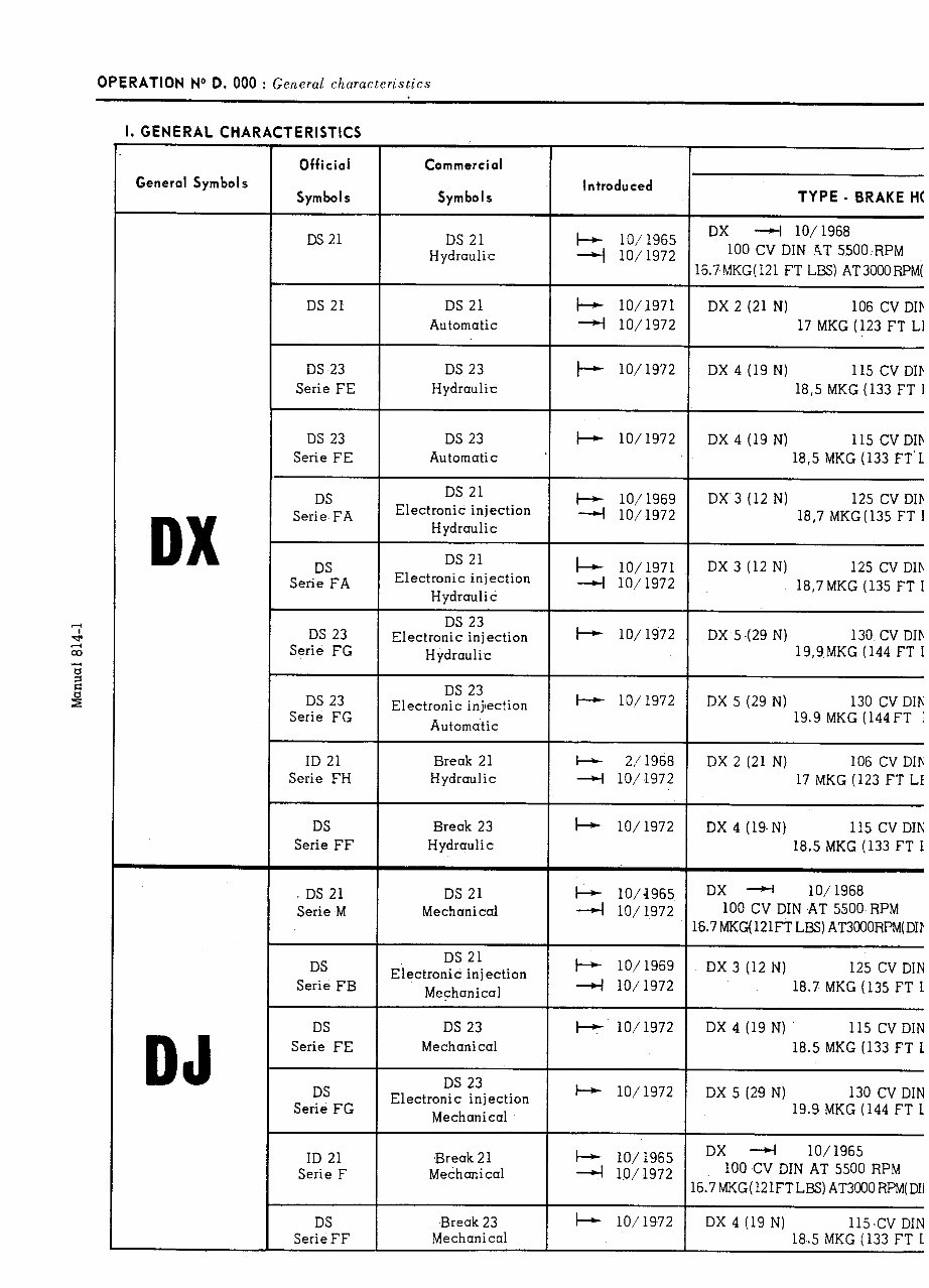
OPERATION No D. 000 : General characteristics I. GENERAL CHARACTERISTICS General Symbols Official Symbols Commercial Symbo1.s Introduced TYPE - BRAKE H( i-+ lo,‘1965 + 10/1972 DX 4 lo/1968 100 CV DIN 4T 55OO:RPM 16.7MKG(121 FT LBS) ATSOOORPM I-+ IO/1971 DX 2 (21 N) 106 CV DIE 4 10/1972 17 MKG (123 FT Ll DS 21 Hydraulic DS 21 DS 21 DS 23 Serie FE DS 23 Serie FE DS 21 Automatic DX 4 (19 N) 115 CV DIP 18,5 MKG (133 FT 1 DS 23 Hydraulic +- 10/1972 DX 4 (19 N) 115 CV DIb 18,5 MKG (133 FT’L DS 23 + 10/1972 Automatic ’ DS 21 Electronic injection Hydraulic I-+ lo/1969 4 10/1972 DX 3 (12 N) 125 CV DIb 18,7 MKG (135 FT I DS Serie FA DX DX 3 (12 N) 125 CV DIh 18,7 MKG (135 FT I DS 21 Electronic injection Hydraulic I- 10/1971 4 10/1972 DS Serie FA DS 23 Electronic injection Hydraulic I-+ 10/1972 DX 5 .(29 N) 130. CV DIb 19,9MKG (144 FT I DS 23 Serie FG DS 23 Electronic injection Automatic t-t 10/1972 DX 5 (29 N) 130 CV DIh 19.9 MKG (144 FT : 1 DX 2 (21 N) 106 CV DIb 17 MKG (123 FT LI Break 21 Hydraulic W 2,‘1968 4 10/1972 DX 4 (19.N) 115 CV DIh 18.5 MKG (133 FT I Break 23 Hydraulic + 10/1972 DS Serie FF DS 21 Serie M t DS Serie FB DS 21 Mechanical k lo/-1965 4 10/1972 DX + lO/ 1968 100 CV DIN AT 5500,RPM 16.7MKG( 121FTLBS) AT3OOORPM(D DX 3 (12 N) 125 CV DI& 18.7 MKG (135 FT I DX 4 (19 N) ’ 115 CV DIN 18.5 MKG (133 FT I DS 23 Mechanical I-+ 10/1972 DJ DX 5 (29 N) 130 CV DIN 19.9 MKG (144 FT I DS 23 Electronic injection Mechanical I-+ 10/1972 DX 4 lO/ 1965 100 CV DIN AT 5500 RPM 16.7MKG(121FTLBS)AT3000RPM(DIi DX 4 (19 N) 115 .CV DIN 18.5 MKG (133 FT I Break 23 Mechanical I-+ 10/1972
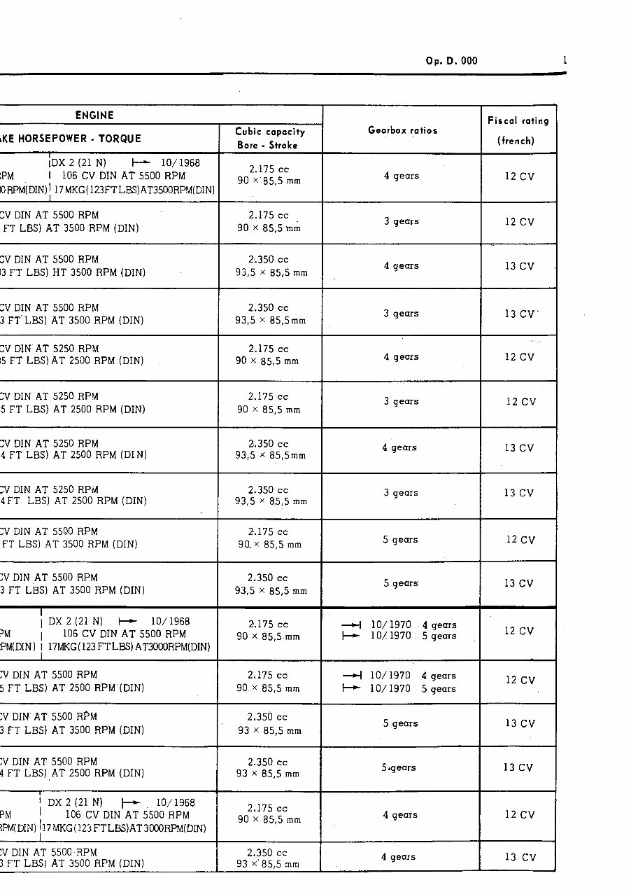
Op. D. 000 ENGINE rKE HORSEPOWER - TORQUE I IDX 2 (21 N) t- IO/1968 IPM 1 106 CV DIN AT 5500 RPM lORPM(DIN)I 17MKG(123FTLES)AT3500RPM(DIN CVDIN AT 5500 RPM FT LBS) AT 3500 RP,M (DIN) :V DIN AT 5500 RPM 13 FT LBS) I-IT 3500 RPM (DIN) CVDIN AT 5500 RPM 3 FT'LBS) AT 3500 RPM(DIN) CIVDIN AT 5250 RPM 15 FT LBS)AT 2500 RPM (DIN) ZVDIN A+ 5250 RPM i5 FT LBS) AT 2500 RPM (DIN) ZVDIN AT 5250 RPM 4 FT LBS) AT 2500 RPM (DIN) ;VDIN AT 5250 RPivl OFT LBS) AT 2500 RPM (DIN) YDIN AT 5500 RPM FT LBS) AT 3500 RPM (DIN) :V DIN'AT 5500 RPM 3 FT LBS) AT 3500 RPM (DIN) I 1 DX 2 (21 N) I--+ lo/1968 ?M 106 CV DIN AT 5500 RPM ;PM(DIN) 1 17MKG(123FTLBS)AT3000RPM(DIN) I :V DIN AT 5500 RPM 5 FT LBS) AT 2500 RPM'(DIN) YDIN AT 5500 RPM 3 FT LBS) AT 3500 RPM (DIN) YDIN AT 5500 RPM 4 FT LBS) AT 2500 RPM (DIN) 1 ; DX 2 (21 N) + lo/1968 PM 106 CV DIN AT 5500 RPM ?PM(DIN)h7MKG(125FTLBS)AT3OOORPM(DIN) :V DIN AT 5500,RPM 3 FT LBS) AT 3500 RPM(DIN) 1 - Cubic capacity Bore - Stroke 2.175 cc 90 X,85,5 mm 2.175 cc 90 x 85,5 mri 2,.350 cc 93,5 x 85,5 mm 2.350 cc 93,5 X 85,5mm 2,.175 cc 90 X 85,5 mm 2.175 cc 90 X 85,5 mm 2,.350 cc 93,5 X 85,5mm 2..350 cc 93,5 X 85,5 mm 2.175 cc 90. x 85,5 mm 2.350 cc 93,5 X 85,5 mm 2.175 cc 90 X 85,5-mm 2.175 cc 90 X 85,5 mm 2.350 cc 93 X 85,5 mm 2.350 cc 93 X 85,5 mm 2.175 cc 90 X 85,5 mm 2.350 cc 93 X,85,5 mm T Gearbox ratios 4 gears 3 gears 4 gears 3 gears 4 gears 3 gears 4 gears 3 gears 5 gears 5 gears 4 lo/1970 4 gears + lo/1970 5 gears 4 lo/1970 4 gears + lo/1970 5 gears 5 gears 5 *gears 4 gears 4 gears Fiscal rating (french) 12 cv 12 cv 13 cv 13CV' , 12 cv 12 cv 13 cv 13 cv 12 cv 13 cv 12 cv 12 cv 13 cv 13 cv 12 cv 13 cv
CHARACTERISTICS OPERATION No D. 000 : General characteristics Op. D. 000 1 i P.T.O. I
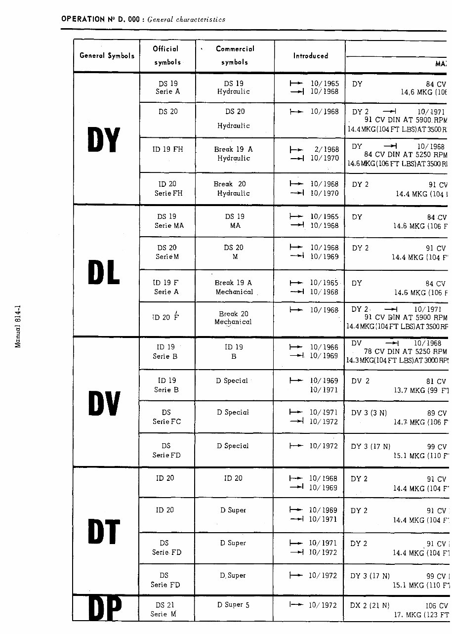
OPERATION No D. 000 : General characteristics Official b Commercial Introduced symbols symbols MA: General Symbols DS 19 Serie A DS 19 Hydraulic b lo/1965 DY 84 CV 4 lo/1968 14,6 MKG (10E DS 20 DS 20 I-+ lo/1968 DY2 4 10/.1971 Hydraulic 91 CV DIN AT 5900 RPM 14.4MKG(104FT LBS)AT3500R ID 19 FH Break 19 A + 2/1968 DY 4 lO/ 1968 Hydraulic 4 10/1970 84 CV DIN AT 5250 RPM 14.6MKG (106FT L!3S) AT 3500 RI ~ ~~~- DY 2 91 cv 14.4 MKG (104 I ID 20 Serie FH DS 19 Serie MA Break 20 k lo/1968 Hydraulic 4 10/1970 DS 19 + lo/1965 MA 4 lo/1968 DY 84 CV 14.6 MKG (106 F DL DS 20 DS 20 + lo/1968 DY 2 91 cv Serie M M 4 lo/1969 14.4 MKG (104 F’ ID 19 F Serie A Break 19 A t-+ lo/1965 DY 84 CV Mechanical 4 lo/‘1968 14.6 MKG (106 F TD 20 b Qreak 20 + lo/1968 DY2, 4 lO/ 1971 MeF$anical 91 CV DIN AT 5900 RPM 14.4MKG( 104 FT LBS)AT 3500RF ID 19 Serie B ID 19 B I-+ lo/1966 4 lo/1969 DV lO/ 1968 78 CV DIN AT 5250 RPM 14.3MKG(104 FT LBS)AT3000 RPI ID 19 Serie B + lo/1969 lO/ 1971 DV 2 81 CV 13.7 MKG (99 F’l D Special DV DS Serie FC D Special I-+ lo/l971 4 10/1972 DV 3 (3 N) 89 CV 14.7 MKG (106 F’ D Special I-+ 10/1972 DS Serie FD DY 3 (17 N) 99 cv 15.1 MKG (110 F’ ID 20 ID 20 b lo/1968 I DY2 91 cv 4 lo/1969 14.4 MKG (104 F’ ID 20 D Super b lo/1969 DY 2 91 cv 4 10/1971 14,.4 MKG (104 F’ DT DS Serie FD DS Serie FD D Super I-+ 10/1971 DY 2 91 cv; 4 10/1972 14.4 MK6 (104 Fl D.Super + lO/ 1972 DY 3 (17 N) 99 cv 1 15.1 MKG (110 F’l DS 21 Serie d D Super 5 I- 10/1972 DX 2 (21 N) 106 CV 17. MKG (123 FT
The CITROEN D Models Workshop Repair Manual is a comprehensive guide designed to assist mechanics and car enthusiasts in servicing and repairing CITROEN D Models produced between the years 1965 and 1975.
This workshop manual provides detailed step-by-step instructions, diagrams, and illustrations to help users effectively maintain and repair their CITROEN D Models. It covers a wide range of topics, including engine, transmission, electrical system, suspension, brakes, and more.
Whether you are a professional mechanic or a do-it-yourself enthusiast, this workshop manual is an invaluable resource that will help you save time and money by enabling you to perform repairs and maintenance tasks with confidence and accuracy.
Key features of the CITROEN D Models Workshop Repair Manual:
Comprehensive coverage of CITROEN D Models produced between 1965 and 1975
Detailed step-by-step instructions for various repair and maintenance procedures
High-quality diagrams, illustrations, and photographs for easy understanding
Coverage of various systems, including engine, transmission, electrical, suspension, brakes, and more
Provides specifications, torque settings, and troubleshooting tips
Written in a clear and concise language for easy comprehension
Perfect for professional mechanics, car enthusiasts, and DIY enthusiasts
With the CITROEN D Models Workshop Repair Manual, you can confidently handle any repairs or maintenance tasks on your CITROEN D Model, ensuring optimal performance and longevity.
Recently Viewed
5,521,897Happy Clients
2,594,462eManuals
1,120,453Trusted Sellers
15Years in Business
Price:
Actual Price:
1965-1975 Citroen D Models Service & Repair Manual