Contents LIVING WITH YOUR CITROEN AX Introduction Safety Rrs c ':--------------------- Buying spare parts and vehicle identification numbers MOT Test Checks Page 0-4 Page 0-5 Page 0-6 Checks earned out from the driver's seat Checks carried out with the vehicle on the ground Checks camed out wIth the vehicle raised Checks carried out on your vehicle's exhaust emission system Page Page Page Page 0·7 0·. MAINTENANCE Routine maintenance General dimenSions and weights Page 0-11 Booster battery ijump) starting Page 0-11 Radio/cassette unit anti-theft system precaution Page 0-11 Jacking Page 0-12 Towing and wheel changing Page 0-13 Conversion factors Page 0-14 Maintenance and servicIng Page ,., lubncants, fluids and capacities Page , .. Maintenance schedule Page '·3 Weekly checks Page , .. Every 6000 miles!1 0 000 km Page , .. - Every 12 000 miles/20 000 km Page 1-11 Every 18 000 miles/3D 000 km Page 1-18 Every 24 000 miles/40 000 km Page 1-19 Every 36 000 miles/50 000 km Page '·20 Every 2 years Page 1-21 SpeclftCalions Page "22
Contents REPAIRS & OVERHAUL Engine and Associated Systems Petrol engine In-car repair procedures Diesel engine IO-ear repair procedures EngtOe removal and general engine ovemaul procedures Cooling, heating and ventIlation systems FueVexhaust systems - c:arburettor petrol models - -. FueVexhaust systems - SlngJe---pomt petrolln)eCtlOn models FueVexhaust systems - multi-point petrollnf8CbOn models FueVexhaust systems - DI8SeI models EmISSHX'\S control systems StartJng and chargIng systems IgnItion system (petrol models) Preheating system (Olesei=rnodels==::.) _ Transmission Clutch Manual transmlSSlOfl Dnveshafts =------ _ Brakes Braking system _ Suspension and steering Suspension and steenng "-'-'''-'---''''----- Body Equipment Bodywork and fittings Electrical Body electrical systems Wiring diagrams Refer 10 Reference Tools and W()(1(lng faCIlities General repair PfOC"ed::;"'::.es= _ Fault finding Index Refer to Chapter 2A Chapter 2B Chapter 2C Chapter 3 Chapter 4A Chapter 4B Chapter 4C Chapter 40 Chapter 4E Chapter SA Chapter 5B Chapter 5C Chapter 6 Chapter 7 Chapter 8 Chapter 9 Chapter 10 Chapter 11 Chapter 12 Page WO·1 Page REF-' Page REF-4 Page REF-S Page INO-1
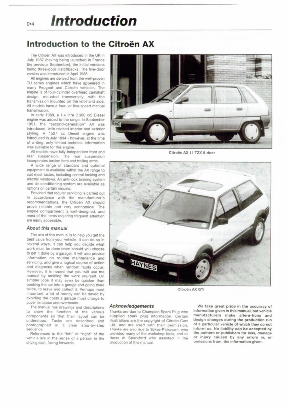
ction In roduc io o e Ci rOe AX Citroen AX 11 TZX 5-door Citroen AX GTI We take great pride in the accuracy of information given In this manual. but vehicle manufacturers make altera-lions and design changes during the production run of a particular vehicle of which they do not Inform us. No liability can be accepted by the authors or publishers for loss, damage or injury caused by any errors in. or omiSSIons from, the information g ven. Acknowledgements Thanks are due to Champion Spark Plug who supplied spark plug Information. Certain Illustra Ions are the copynght 0 Crtroen Cars Ltd, and are used with their permiSSion. Thanks are also due to Sykes-Plckavant. who provided many of he workshop tools. and all those at Sparkford who assisted In the producuon of IS manual The Citroen IV< was Introduced In the UK In July 1987 (having being launched in France he previous September), the imtial versions being three-door Hatchbacks. The five-door version was introduced in April 1988. All engines are denved from the well-proven TU series engines which have appeared in many Peugeot and Citroen vehIcles. The engine IS of four-cylinder overhead camshaft design. mounted transversely. With the transmission mounted on the left-hand Side. All models have a four- or five-speed manual ransmisslon In early 1989. a 1.4 litre (1360 ccl Diesel engine was added to the range. In September 1991. the ·second-generatlon" AX was introduced, with revised interior and extenor styling. A 1527 cc DIesel engine was introduced In July 1994 - however, at the time of Writing, only limited technical information was available for this engine. All models have fUlly-independent front and rear suspension. The rear suspension incorporates torsion bars and trading arms. A Wide range of standard and optional equipment IS available Within he IV< range 0 SUit most tastes. Including central locking and electric Windows. An anti-Ioc bra Ing system and air conditioning system are available as options on certain models. ProVided that regular seMclng IS earned out In accordance With the manufacturer's recommendations. the Citroen IV< should prove reliable and very economical. The engine compartment IS well-designed. and most of he items reqUiring frequent attention are easily accessible About this manual The aim of thiS manual IS to help you get he best value from your vehicle. It can do so In several ways It can help you deCide what work must be done (even should you choose to get It done by a garage). It will also provIde Information on routine maintenance and servIcing. and give a logical course of action and diagnosis when random faults occur. However. it IS hoped that you will use he manual by tackling the work yourself. On simpler Jobs It may even be qUicker than booking he car Into a garage and gOing here tWice. to leave and collect It. Perhaps most Important. a 10 of money can be saved by avoiding the costs a garage must charge to cover Its labour and overheads. The manual has draWIngs and descnptlons to show the function of the various components so that their layout can be understood. Tasks are described and photographed In a clear step-by-step sequence. References to the "left" or "rlgh of he vehicle are in the sense of a person In the driving seat, facing orwards.
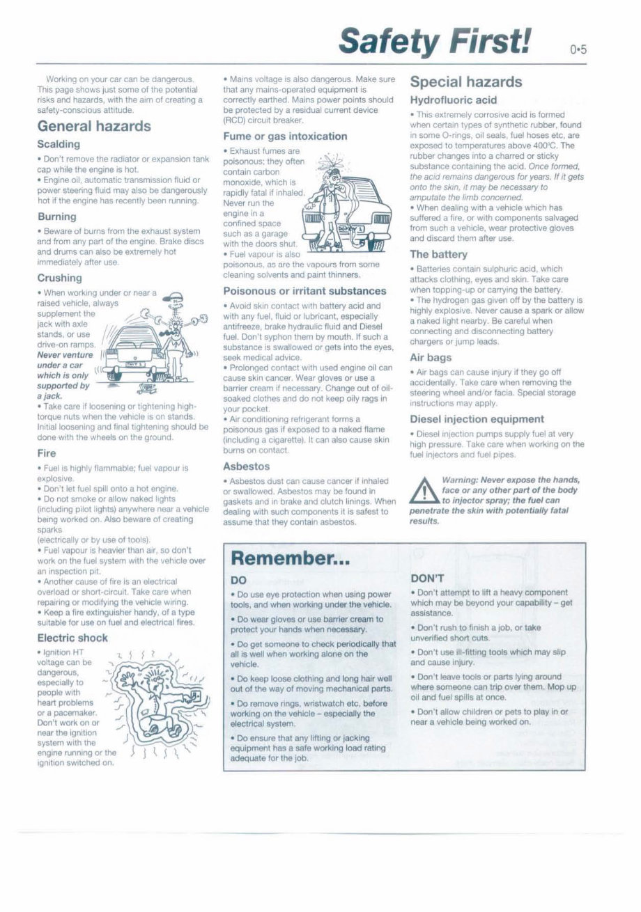
• I~ , • o·s DONT • Don't attemp to hft a heavy component which may be beyond your capability - get assistance. • Don't rush to finish a job, or take unverified short cuts. • Don't use ill-frtllng tools which may slip and cause InJury. • Oon'1 leave 0015 or parts lying around where someone can tnp over them. Mop up oil and fuel spills at once. • Don't allow children or pets a play In or near a vehicle being worked on. The battery • Batteries contain sulphunc aCid which a tacks clothing, eyes and skin. Take care when toppmg-up or carrying the battery • The hydrogen gas given off by the battery IS highly explosIve Never cause a spark or allow a naked light nearby Be carefUl when connec Ing and disconnecting battery chargers 01 jump leadS. Air bags • Air bags can cause Injury if they go off accidentally. Take care when removing the steenng wheel and/or faCia. Special storage Instructions may apply Diesel mjection equipment • Diesel injection pumps supply fuel at very high pressure Take care when working on the luel Injectors and fuel pipes Special hazards Hydrofluoric acid • This extremely corrosive aCid IS fanned when certain types of synthetic rubber found In some O-nngs all seals, fuel hoses etc. are exposed to tempera ures above 400'C The rubber changes Into a charred or sticky substance containing the aCid. Once formed, the aCid remi1lns dangerous for years. If It gets onto the skm, II may be necessary to ampulate the 11mb concerned. • When dealing With a vehicle which has suffered a fire. or With components salvaged from such a vehicle, wear protective gloves and discard them after use. A wamin g: Never expose the hands, , face or any other part of the body • to injector spray; the fuel can penetrate the sk{n with potentially fatal results. DO • Do use eye protection when using power tools, and when working under the vehicle. • Do wear gloves or use barrier cream to protect your hands when necessary. • Do get someone to check period cally that alliS well when working alone on the vehicle. • Do keep loose clothing and long half well oul of the way of moving mechanical parts. • Do remove nngs, wnstwatch etc. before working on the vehicle - especially the eleclncal system. • Do ensure tha any lifting or jacking equipment has a safe working load ra1lnQ adequa e for the job. Remem er ... Asbestos • Asbestos dust can cause cancer If Inhaled or swallowed. Asbestos may be found lO gaskets and In brake and clutch Imings. When dealing With such components It IS safest to assume that they contain asbestos. • MainS voltage IS also dangerous. Make sure that any mains-operated eqUipment is correctly earthed. Mains power points should be protected by a residual current deVice (RGD) CirCUlI breaker Fume or gas intoxication • Exhaust iumes are poisonous; they often contain carbon monoxide, which is rapidly fatal if Inhaled Never run the engine In a can Ined space such as a garage with he doors shut • Fuel vapour IS also pOisonous, as are the vapours from some cleaning solvents and paint thlOners. Poisonous or irritant substances • Avoid skin contact With battery acid and With any fuel, flUid or lubncant, especially antifreeze, brake hydraulic fluid and Diesel fuel. Don't syphon them by mouth. If such a substance IS swallowed or gets into the eyes, seek medical adVice • Prolonged contact with used engine all can cause skin cancer. Wear gloves or use a barner cream If necessary Change out of 011- soaked clothes and do not keep olty rags In your pocket. • Air conditioning relngerant forms a pOisonous gas If exposed 10 a naked flame (including a cigarette) I can also cause skin burns on conlact I ? 1. \ • Ignllion HT voltage can be dangerous, especially to people With heart problems or a pacemaker. Don't work on or near the ignition system With the engine run fling or the Ignition sWitched on. Working on your car can be dangerous This page shows Just some of the potential risks and hazards, with the aim of creaung a safety-conscIous attitude General hazards Scalding • Don't remove the radiator or expansion tank cap while the engine IS hot • Engine all. automatic transmission fluid or power s eering fluid may also be dangerously hot if the engine has recen Iy b en running Burning • Beware of bums from the exhaust system and from any part of the engine Brake discs and drums can also be extremely hot Immediately after use. Crushing • When working under or near a -=3 raised vehicle, always 9 supplement the ------.G......'(j Jf;;. ~ Jack With axle -=: ~ ~~ stands or use 1.1J!.~~E~"f·~~ dnve-on ramps. 'mli Never venture II II under a car I,(I( Iji==:~~~~,- which ;s only _ supported by a jack. • Take care If loosening or tightening hlgh- torque nuts when the vehicle IS on stands. Inllialloosenlng and final Ightenlng should be done With he wheels on the ground Fire • Fuel is highly Ilammable; fuel vapour Is explOSiVe. • Don't let fuel spill onto a hot engine. • Do not smoke or allow naked IIgh s (including pilo lights) anywhere near a vehicle being worked on. Also beware 01 creating sparks (electncally or by use of tools). • Fuel vapour IS heavier than air, so don't work on the fuel system With the vehicle over an inspection pi . • Another cause of fire IS an electncal overload or shan-CircUit Take care when repamng or modifying the vehicle wlnng. • Keep a fire extinguisher handy, of a type suitable for use on fuel and electncal fires. Electric shock
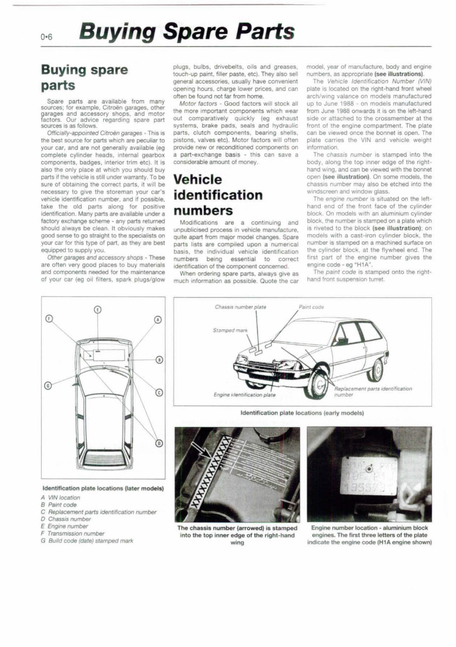
0·6 Spare Part s are Spare parts are available Irom many sources; for example, Citroen garages, other garages and accessory shops, and motor lactors, Our advice regarding spare part sources IS as follows. Officially-appointed Citroen garages - This IS the bes source for parts which are peculiar to your car, and are not generally available (eg compie e cyllnder heads, Internal gearbox components, badges, Interaor tram etc). It IS also the only place at which you should buy pans If the vehicle IS stili under warranty To be sure of obtaining the correct parts, it Will be necessary to give the storeman your car's vehicle Identification number, and if possible, take he old parts along for positive Identification. Many parts are available under a factory exchange scheme· any parts returned should always be clean It obviously makes good sense 0 go straight to the specialists on your car for this type 01 part, as they are best equipped 0 supply you. Other garages and accessory shops - These are often very good places to buy matenals and components needed lor the maintenance of your car (eg 011 filters, spark plugs/glow plugs. bulbs, dnvebelts. oils and greases. touch-up pain, Iller paste, etc) They also sell general acceSSOries, usually have convenient opening hours, charge lower prices, and can often be ound no far rom home. Motor factors - Good factors Will stock all the more Important components which wear out comparatively qUickly (eg e haust systems, brake pads, seals and hydraulic parts, clutch components, bearing shells, pistons, valves etc). Motor factors will often provide new or reconditioned components on a part-exchange basIs· hiS can save a conSiderable amount of money. Vehicle identification numbers Modifications are a continuing and un publiCised process in vehicle manufacture, QUIte apart rom malor model changes Spare parts lists are compiled upon a numeracal baSIS, he indiVidual vehicle identlflcalion numbers being essential 0 correct identification of the component concerned When ordering spare parts, always give as much Informa Ion as pOSSible. Quote th car model. year of manufacture. body and engine numbers, as appropriate (see illustrations) The Vehicle IdentificatIOn Number (VIN) plate IS located on the nght-hand front wheel arch/wing valance on models manufactured up to June 1988 - on models manufactured from June 1988 onwards It IS on the Ie -hand Side or attached to the crossmember at he front of the engine compartment. The plate can be Viewed once the bonnet IS open. The plate carnes the VIN and vehIcle weight Informalion. The chaSSIS number IS stamped In a he body. along the lOP Inner edge 01 the right· hand wing. and can be viewed With the bonne open (see illustration). On some models. the chaSSIS number may also be etched Into the Windscreen and Window glass. The engme number IS situated on the Ie - hand end of the front face of the cylinder block On models With an aluminium cylinder block. the number IS stamped on a plate which IS riveted to the block (see Illustration) on models With a cast-Iron cylinder block. the number is stamped on a machined surface on the cylinder block. at the flywheel end. The first part of the engine number gIves the engine code - eg "H1A The pamt code IS stamped onto the rlght- hand ron suspensIon urrel. Identification plate locations (early models) Engine number location - aluminium block engines. The first three letters of the plate indicate the engine code (H1A engine shown) The chassis number (arrowed) is stamped into the top inner edge of the right-hand wing Chessls number plale o Identification plate loeations (later models) A VIN location B Pam/code C Replacement parts Identification number D ChaSSIS number E Engine number F TransmiSSion number G BUild code (date) stamped mark
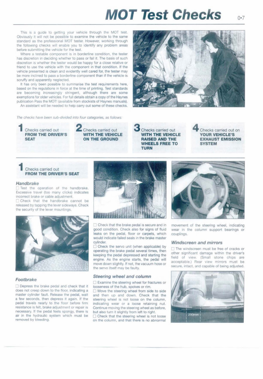
e c 0-7 This is a gUide 10 getting your vehicle Ihrough the MOT les\' ObViouSly I viII nol be possible to examine he vehicle to the same slandard as the professional MOT tester However, working hrough the following checks will enable you 10 Identify any problem areas before submitting the vehicle for he tesl Where a testable compon n IS In borderline condition, he tester has dlscreliOn In deciding whether 10 pass or fall It. The baSIS of such discre ion IS whether Ihe ester would be happy for a close relative or fnend to use the vehicle '.'11th the component In that condition. If the vehicle pr sented is clean and eVidently well cared for, he tester may be more Inclined to pass a borderline component than If the vehicle IS scruffy and apparently neglected I has only been possible to summarise the lest reqUiremenls here, based on the regUlations In force at Ihe time of pnntlng. Test standards are becommg increasingly stringent. although Ihere are some exemptions for older vehicles, For full details obtain a copy of lhe Haynes publication Pass the MOT! (available from stockists of Haynes manuals) An assistant '.'1111 be needed to help carry out some of these checks The checks IJave been sub·divided into four categones, as follows: 1 Checks earned out FROM THE DRIVER'S SEAT 2 Checks carried out WITH THE VEHICLE ON THE GROUND Checks carried out WITH THE VEHICLE RAISED AND THE WHEELS FREE TO TURN Checks carried out on YOUR VEHICLE'S EXHAUST EMISSION SYSTEM 1 Checks carried out FROM THE DRIVER'S SEAT Handbrake Tes h operation 01 the handbrake. ExceSSive travel (too many clicks) indicates Incorrect brake or cable adjustment Check Ihal Ihe hand brake cannot be released by lapping Ihe lever Sideways. Check the security of the lever mountings. Footbrake -' Depress Ihe brake pedal and check thaI It does not creep down 10 Ihe loor, indicating a master cylinder faull. Release he pedal, wall a few seconds. lhen depress I again. If the pedal Iravels nearly to Ihe floor before flfm resistance IS felt brake adjustment or repair IS necessary If the pedal feels spongy, there Is air In the hydraulic system which must be removed by bleeding I I Check Ihat the brake pedal IS secure and In good condition. Check also for signs of flUid leaks on the pedal, floor or carpets, which would Indicate failed seals In the brake master cylinder. o Check Ihe servo uM (when applicable) by operallng Ihe brake pedal several limes, then keeping the pedal depressed and starting the engine. As the engine starts, the pedal '.'1111 move down slightly, If not, the vacuum hose or Ihe servo Itself may be faulty. Steering wheel and column _ Examine the steenng wheel for fractures or looseness of Ihe hub, spokes or rim. LJ Move Ihe steering wheel from side to Side and Ihen up and down Check that the sleering wheel 15 not loose on the column, Indicating wear or a loose retaining nul. Continue moving the steering wheel as before, but also turn II slightly from left to nghl. n Check hat the steering wheel IS nol loose on the Column, and Ihat lhere Is no abnormal movemen of the steenng wheel, indicating wear in the column support bearings or couplings. Windscreen and mirrors D The Windscreen musl be free of cracks or other significant damage WI hin the dnver's field of vIew (Small slone chips are acceptabl .) Rear view mirrors must be secure, Intact, and capable 01 being adJusted
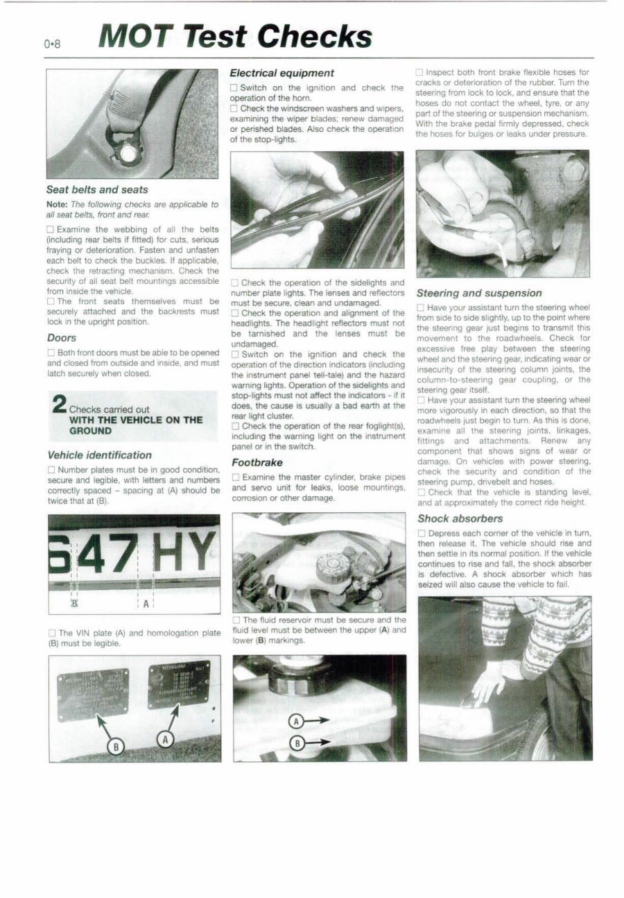
Steering and suspension o Have your assistant tum the steering wheel from Side to Side slightly, up to the point where the steering gear Just beginS to transmrt this movement to the roadwheels. Check for excessive free play between the steenng wheel and the steenng gear. Indicating wear or insecunty of the steering column joints, he column-to-steerlng gear coupling, or the steering gear itself. _ Have your assistant turn the steering wheel more vigorously In each direction, so that the roadwheels Just begin to turn As thiS IS done, examine all the steering JOints, linkages, fittings and attachments. Renew any componen that shows signs of wear or damage On vehicles With power steering, check the security and condition of he steering pump, dnvebelt and hoses. Check hat the vehicle IS standing level. and a apprOXimately the correc ride height. Shock absorbers C Depress each corner of the vehicle in turn then release it. The vehicle should nse and then settle In Its norma! position. If the vehicle continues to rise and fall. the shock absorber is defective. A shock absorber which has seized will also cause the vehicle to fail. '= Inspec both front brake flexible hoses for cracks or deterroratlon of the rubber. Turn the steering from lock to lock, and ensure hat the hoses do not contact the wheel, tyre, or any part of the steering or suspension mechanism. With the brake pedal firmly depressed. check the hoses for bulges or leaks under pressure. :I The flUid reservoir must be secure and the tkJld level must be between he upper (A) and lower (B) markings. I' Check he operation of the Sidelights and number plate lights. The lenses and reflectors must be secure, clean and undamaged. o Check the operation and alignment of the headlights. The headlight reflectors must not be tarnished and the lenses must be undamaged. ..J Switch on the Ignition and check the operation of he dfrectJon indicators (Including the Ins rumen panel tell-tale and the hazard waming lights. Operation of he sidelights and stop-lights must not affect the indicators - If It does, the cause is usually a bad earth at he rear light cluster. o Check the opera ion 0 he rear fogl/ght(s), Including the waming light on he instrument panel or in he swi ch. Footbrake C Examine the master cylinder, brake pipes and servo unit for leaks, loose mountings, corrosion or other damage. Electrical equipment o Switch on he igmtlon and check he operation of the horn. ;) Check the windscreen washers and wipers, ~amining the wiper blades: renew damaged or perished blades. Also check the operation o the stop-lights. --=---t Check I I A: 2 Checks carried out WITH THE VEHICLE ON THE GROUND Vehicle identification o Number pia es must be In good condition. secure and legible, With letters and numbers correctly spaced - spacing at (A) should be twice that at (B) C The VIN plate CAl and homologation plate IB) must be legible. Seat belts and seats Note: The followmg checks are applicable to all seat belts, front and rear o Examine the webbing of all the belts (including rear belts if fitted) for cuts, serious fraying or deterioration. Fasten and unfasten each belt to check the buckles. If applicable, check the retracting mechanism. Check the secunty of all seat belt mountings accessible from InSide the vehicle C The fron seats themselves must be securely attached and he backrests must lock In the upright posrtlon Doors o Both front doors must be able to be opened and closed from outside and inSide. and must latch securely when closed. o-a
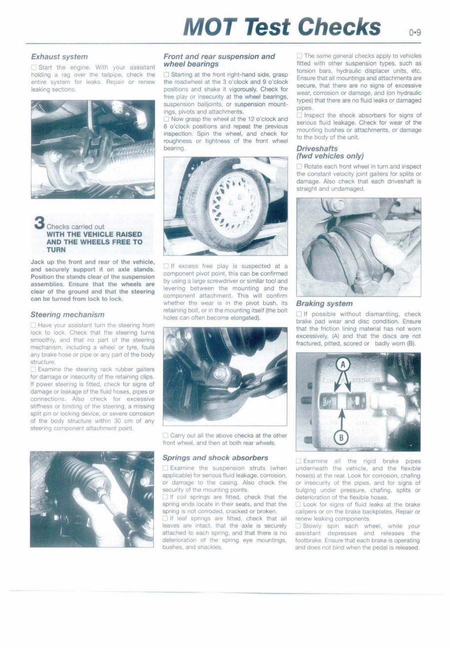
e c o·g [J The same general checks apply to vehicles fitted With other suspension types, such as torsion bars. hydraulic dlsplacer Units, etc. Ensure that all mountings and attachments are secure, that there are no signs of e cesslve wear, corrosion or damage, and (on hydraulic ypesl har here are no flUid leaks or damaged pipes. = Inspec the shock absorbers for signs of serious fluid leakage. Check for wear of the mounting bushes or attachments, or damage to the body of the unit Driveshafts (fwd vehicles only) Rotate each front wheel In tum and Inspec the constant velOCity jOint gaiters for spl! s or damage Also check that each dnveshaft IS straight and undamaged. Braking system ] If possible Without dismantling, check brake pad wear and disc condition Ensure that the fnctlon II01n9 matenal has not worn excessively, (A) and that the diSCS are not Iractured, Pitted. scored or badly wom (B). ~ Examine all he ngld brake pipes underneath he vehicle, and he fleXible hosels) at the rear. Look for corroSion, chafing or insecurr y of the pipes, and for signs a bUlging under pressure, chafmg, splits or deterioration of the flexible hoses J Look for Signs of flUid leaks at the brake calipers or on the brake backplates Repair or renew leaking components. Slowly spin each wheel, while your assistant depresses and releases the footbrake. Ensure thaI each brake IS operating and does not bind when the pedal IS released. Carry out all the above checks at the a her tront wheel and then at both rear wheels. II excess free play is suspected at a component pivot pOint, thiS can be confirmed by uSing a large screwdnver or Similar tool and levering between the mounting and the component attachment ThiS will confirm whether the wear IS 10 the PiVOt bush, Its retaining bolt, or 10 the mountrng itself (the bolt holes can often become elongated). Front and rear suspension and wheel bearings 'j Starting at the fron right-hand side, grasp the roadwheel at he 3 o'clock and 9 o'clock positions and shake i vigorously. Check lor Iree play or Insecunty at the wheel beanngs, suspension balfjornts. or suspension mount- Ings, pivotS and attachments. cJ Now grasp the wheel at the 12 o'clock and 6 o'clock poslt:JOns and repeat the prevIous inspection. Spin the wheel, and check for roughness or tightness of the front wheel bearing Springs and shock absorbers - Examine the suspension struts (when applicable) or senous lIU1d leakage, corrosion. or damage 0 the casing Also check the secull1y of the mounting pornts If COil spnngs are fitted, check that he spnng ends locate In their seats. and that the sprmg is not corroded, cracked or broken If leaT spnngs are filled. check thaI all leaves are ,n act. hat the axle is securely attached a each spring and that there IS no deterroratlon ot the spring eye mountings, bushes and shackles, Exhaust system Start the englOe. With your assistant holding a rag over he ailplpe, check he entire system or leaks Repair or renew leaking sections. Jack up the front and rear of the vehicle, and securely support it on axle stands. Position the stands clear of the suspension assemblies. Ensure that the wheels are clear of the ground and that the steering can be turned from lock 10 lock. 3 Checks carried out WITH THE VEHICL£ RAISED AND THE WHEELS FREE TO TURN Steering mechanism ~ Have tOW asslstarll lurn the s eerlng from lock to lock Check hat the steering urns smoothly, and that no part 01 the s eerlng mechanism, Including a ,vheel or tyre, fouls any brake hose or pipe or any part of the body structure. Examine the steering rack rubber gaiters for damage or insecurity of the retaining clips II power s eerlng IS Itted, check for signs of damage or leakage of he flUid hoses, pipes or connectIOns Also check for excessive s I ness or binding of he steering, a missing sph pm or locking device or severe corrOSion of the body structure within 30 em 01 any steenng component attachment point
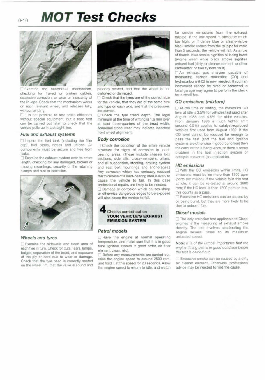
Diesel models ::: The only emission test applicable to Diesel engll1es IS the measunng of e haust smoke denSity The test Involves accelerating the engtne several Imes to I s maximum unloaded speed Note: It IS of the utmost importance thaI the engine timing belt is In good condition before the lest IS earned out .., ExcesSive smoke can be caused by a dirty alt cleaner elemenl Otherwise, profesSional adVice may be needed to Ind the cause. HC emissions ~ With the CO emiSSions within limits, HC emiSSions must be no more han 1200 ppm (parts per million). If he vehicle falls thiS tes1 at Idle, It can be re-tested at around 2000 rpm If the HC level IS then 1200 ppm or less, thiS counts as a pass :::::; ExcesSive HC emissions can be caused by 011 betng burn • but they are more likely 0 be due to unbumt fuel. CO emissions (mixture) ...J At the time or wntlng, the maximum CO level at Idle is 3.5% for vehicles first used after August 1986 and 4 5% for older vehicles. From January 1996 a much tlgh er limit (around 0.5%1 applies 0 catalyst-eqUipped vehicles firs used from August 1992. If the CO level canna be reduced far enough to pass the est (and the fuel and ignition systems are otherwise in good condition) then he carbure or IS badly worn, or there IS some problem In the fuel Il1Jectlon system or catalytic converter (as applicable). for smoke emissions from the exhaust ailplpe If the Idle speed IS obViously much 00 high. or I dense blue or clearly-vIsible black smoke comes from the tailpipe for more han 5 seconds, the vehicle Will fail. As a rule of thumb, blue smoke Signifies 011 being burnt (engine wear) while black smoke signifies unburnt fuel (dirty air cleaner element. or other carburettor or fuel system fault). o An exhaust gas analyser capable of measuring carbon monoxide (CO) and hydrocarbons (HC) is now needed. If such an Instrument cannot be hired or borrowed, a local garage may agree to perform the check or a small fee. Petrol models '--.J Have he engine a normal operating temperature. and make sure hat It is in good tune (ignition system In good order, air flI er elemen clean. etc). ':::::i Before any measurements are carried out, raise the engine speed to around 2500 rpm and hold It at thiS speed for 20 seconds Allow he engine speed to return to Idle, and watch 4 Checks carried out on YOUR VEHICLE'S EXHAUST EMISSION SYSTEM properly sea ed, and hat the Wheel is no distorted or damaged. =: Chec that he lyres are of the correct size for he vehicle. ha they are of he same size and type on each axle, and that the pressures are correc o Check the yre tread depth. The legal minimum a the time of writing Is 1.6 mm over at leas three-quarters 0 he tread Width. Abnormal tread wear may Indicate Incorrect front wheel alignment. Body corrosion Check the condition of he en Ite vehicle s rue ure or signs 0 corrosion In load- beanng areas. (These Include chaSSIS box sections, side sills, cross-members, pillars, and all suspenSion, steenng, brakIng system and sea belt mountings and anchorages.) Any corrOSion which has senously reduced the thlC ness 0 a load-bearing area IS likely to cause the vehicle to fall. In thiS case professional repairs are likely to be needed c: Damage or corrosion which causes sharp or otherwise dangerous edges to be exposed will also cause the vehicle to fall. --=----t Check Wheels and tyres o Examine the sidewalls and tread area of each lyre In turn. Check for cuts. tears. lumps. bUlges, separation of he tread and exposure of the ply or cord due to wear or damage. Check that he tyre bead is correctly seated on the wheel nm, tha he valve is sound and D Examine the handbrake mechanism. checking or rayed or broken cables excessive corrosion. or wear or Insecunty of the linkage Check ha the mechanism works on each relevant wheel. and releases fully. withou binding L-' It IS not possible to test brake effiCiency without special equipment, but a road est can be carried out later to check that the vehicle pulls up In a stralgh line Fuel and exhaust systems U Inspect the fuel tank (including the filler cap), fuel pipes, hoses and unions. All components must be secure and free from leaks C Examine the exhaust system over Its enUre length, checking for any damaged. broken or missing mountings, secunty of the retaining clamps and rust or corrosion 0-10
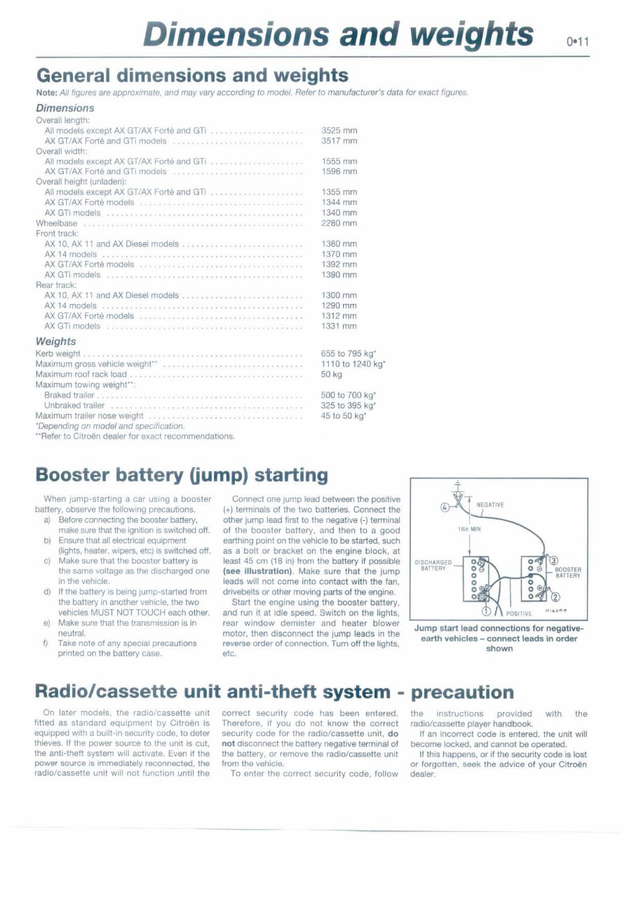
Dimensions and weights 1555 mm 1596 mm 3525 mm 3517 mm 1300 mm 1290 mm 1312 mm 1331 mm 1355 mm 1344 mm 1340 mm 2280 mm 1380 mm 1370 mm 1392 mm 1390 mm General dimensions and weights Note: All figures are approximate, and may vary according to model. Refer to manufacturer's data for exact figures. Dimensions Overall length: All models except AX GT/AX Forte and GTi . AX GT/AX Forte and GTi models . Overall width: All models except AX GT/AX Forte and GTi . AX GT/AX Forte and GTi models . Overall height (unladen): All models except AX GT/AX Forte and GTi . AX GT/AX Forte models . AX GTi models . Wheelbase . Front track: AX 10, AX 11 and AX Diesel models . AX 14 models . AX GT/AX Forte models . AX GTI models . Rear track: AX 10, AX 11 and AX Diesel models . AX 14 models . AX GT/AX Forte models . AX GTi models . Weights Kerb weight . Maximum gross vehicle weight" . Maximum roof rack load . Maximum towing weight": Braked trai ler . Unbraked trailer . Maximum trailer nose weight . 'Depending on model and specification. "Refer to Citroen dealer for exact recommendations. 655 to 795 kg' 1110 to 1240 kg' 50 kg 500 to 700 kg' 325 to 395 kg' 45 to 50 kg' Booster battery (jump) starting When jump-starting a car using a booster battery, observe the following precautions. a) Before connecting the booster battery, make sure that the ignition is switched off. b) Ensure that all electrical equipment (lights, heater, wipers, etc) is switched off. c) Make sure that the booster battery is the same voltage as the discharged one in the vehicle. d) If the battery is being jump-started from the battery in another vehicle, the two vehicles MUST NOT TOUCH each other. e) Make sure that the transmission is in neutral. f) Take note of any special precautions printed on the battery case. Connect one jump lead between the positive (+) terminals of the two batteries. Connect the other jump lead first to the negative (-) terminal of the booster battery, and then to a good earthing point on the vehicle to be started, such as a bolt or bracket on the engine block, at least 45 cm (18 in) from the battery if possible (see illustration). Make sure that the jump leads will not come into contact with the fan, drivebelts or other moving parts of the engine. Start the engine using the booster battery, and run it at idle speed. Switch on the lights, rear window demister and heater blower motor, then disconnect the jump leads in the reverse order of connection. Turn off the lights, etc. ~ """" 18in MIN DISCHARGED BATTERY Jump start lead connections for negative- earth vehicles - connect leads in order shown Radio/cassette unit anti-theft system - precaution On later models, the radio/cassette unit fitted as standard equipment by Citroen is equipped with a built-in security code, to deter thieves. If the power source to the unit is cut, the anti-theft system will activate. Even if the power source is immediately reconnected, the radio/cassette unit will not function until the correct security code has been entered. Therefore, if you do not know the correct security code for the radio/cassette unit, do not disconnect the battery negative terminal of the battery, or remove the radio/cassette unit from the vehicle. To enter the correct security code, follow the instructions provided with the radio/cassette player handbook. If an incorrect code is entered, the unit will become locked, and cannot be operated. If this happens, or if the security code is lost or forgotten, seek the advice of your Citroen dealer.
Introducing the 1986-1998 CITROEN AX Service and Repair Manual - your go-to guide for maintaining and fixing your beloved Citroen AX model. Whether you're a seasoned car enthusiast or a DIY beginner, this comprehensive manual is designed to provide you with all the information you need to keep your Citroen AX running smoothly for years to come.
Model year: 1986-1998
Make: Citroen
Model: AX
This manual covers a wide range of topics, including:
Regular maintenance procedures
Engine repairs and adjustments
Electrical system troubleshooting
Brake system repairs
Suspension and steering maintenance
Transmission and drivetrain repairs
And much more!
With detailed step-by-step instructions, diagrams, and illustrations, this manual makes even the most complex repairs feel manageable. Say goodbye to expensive trips to the mechanic and take control of your own car maintenance.
Don't let car troubles slow you down. Get the 1986-1998 CITROEN AX Service and Repair Manual today and ensure your beloved Citroen AX stays in top-notch condition.