

Chrysler Valiant VC Workshop Manual
What's Included?
Fast Download Speeds
Online & Offline Access
Access PDF Contents & Bookmarks
Full Search Facility
Print one or all pages of your manual
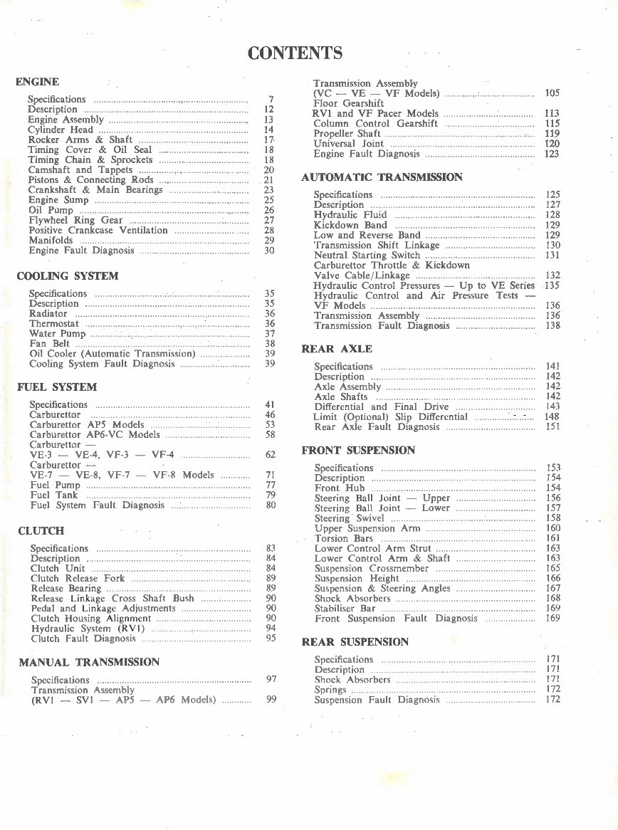
CONTENTS
ENGINE
Speci~caotions 0 0 0 0 0 0 0 0 0 0 0 0 0 0 0 0 0 0 0 .. 0 0 .. 0 0 0 0 0 0 0 0 0 0 .... 0 0 0 0 0 .. 0 0 0 .. 0 0 .. 0 0 .. 0 ..
Descnptwn Oo ooo oo 000 ooO OO oooo oO ooo.oooo .o.oo ·oo·Oooo ·o· .o.o· ·oo ... 0000 ·o· o ..
Engine Assembly 00 .... ooOO· 000000 .. 00 0 •oooooooooooo.oo .... ............. 0
Cylinder Head .. 00 00.00 00.00 ......... 00 ..... .. 00 .. 00 ..... 00 00 .. 0 00 .. 0 00 .. .
Rocker Arms & Shaft 00 .. oo .. oo . 00 00 00 .. o ... 00.00 .... 00 00.00 .... 0
Timing Cover & Oil Seal 00 .. .. .. oo ........... 00 00 00 00 .. 00 00 0
Timing Chain & Sprockets 00 ..... 00 00 ... 00 00 .00 .. 00 00 00.00 .. ..
Camshaft and Tappets ···· ······ ·oo· · .. ........ . 00 ....... o .. oooo.
Pistons & Connecting Rods .. ·oo .......... 00 0000 .. 00 00 00 .... ..
Crankshaft & Main Bearings oo·oo .. oo ...... oo .. . oo .... .... oo
Engine Sump o .......o oo o.o ...... .......... ...... oo ......... ooooOoo• 0000000
Oil Pump o .... oo .. oo .... oooooo••oo·•oo•oo• .. oo .. oooOoo .............. .... ... ..
Flywheel Ring Gear .oo .... oooo ..... oo ... ·······oo .·oo ·oooo ·oooooooo
Positive Crankcase Ventilation ....... oo ... ... .... oo ... oo .. ..
Manifolds oooooooo ·· ··· ·ooo .. ooo•oo··o·o···oooooooooo ... . oooooooo ·o ·· ···· oo ·· o
Engine Fault Diagnosis . ·· oo·· ····oo· .oooo ........ oo. oo oo ·oo·oo ... o
COOLING SYSTEM
~~~ifl~~i~~ns .. o :::::::::::::::::::::::::::::::::::::::::::::::: :: :: : ::::: :: ::
Radiator .o ...o .oo oooooooooooooo · •·oo•Ooooooo.o.oo .. ooooo ·.o·oo ·o···oooo ·· .. ··o
Thermostat .0 0 0. 0000 .. 00 00 oo· 0 00 .. 0. 0. 00 .... 0. 0. 00 .. 0 ... 00. oo· .... 0 0 .. 0 .. 0 ...
Water Pump .... oooooooooo.oo ........ ooooooo .... .. ooo ... oo ...... oo .. oooo ... .
Fan Belt ..... .. oo· ·· ··oo ·· ·· ······· ···· ··· ·oo·· ···· ···· ·oo ·· ·oooo .oooooo ··oOoo
Oil Cooler (Automatic Transmission) ...... oooo·oO·oooOoo
Cooling System Fault Diagnosis ... oooo.oo . 00 ooooo ........ oo
FUEL SYSTEM
Specifications .. .. .. . ooo 00 .. oo ... oo oo ......... oo 00 •oo· 00 00 ... oo .......... ..
Carburettor o· ··o 0000. ··o·· o ·· .. .. .... ...... ...... ··o · ·· ·o ·.o· o ·.oooo ·o ·· ··o
Carburettor AP5 Models ··oooo••oo·· ·· .. ........ oooooo ....... ..
Carburettor AP6-VC Models oo ..... oo .. oo ...... . oo ..... oo ... oo
Carburettor -
VE-3 - VE-4, VF-3
Carburettor -
VF -4
VE-7 - VE-8, VF-7 VF-8 Models ..... ...... .
Fuel Pump oooooo .. oo .. oo·· ······oo·· .. oo·oo••oo•oo ··· .. ·oo···. ·oooooooo ·oo
Fuel Tank oo.oo.oo•oo····oooooo·oo···oo·oo···· .. ........ ....... o·oo .. ··o .. .
Fuel System Fault Diagnosis ... .. ..... ·oo •oooo ..... .... .. . oo
CLUTCH
Speci~caotions ... 00........... .............. 00 00 .. .
Descnptton 00 .oo .. oo 0000 .oo ....... .. . oo .......... .. ... . oo .. .
Clutch Unit . . .. oo .... oo .. ... .............. .. ..
Clutch Release Fork .
Release Bearing ........ ..... .
Release Linkage Cross Shaft Bush ... ..
Pedal and Linkage Adjustments ..
Clutch Housing Alignment oo• .... oo ................ .... ..... ..
Hydraulic System (R VI) .. ........ .. oo ... oo .o ooooo .... 00 .. 0
Clutch Fault Diagnosis .... oo .............. . 00 ... 00 ..... ..... ... ..
MANUAL TRANSMISSION
Specifications ... oo. ·oo· oo·· ... oo .. oo oooo· ... .......
Transmission Assembly
(RVI - SVI - AP5 - AP6 Models)
7
12
13
14
17-
18
18
20
21
23
25
26
27
28
29
30
35
35
36
36
37
38
39
39
41
46
53
58
62
71
77
79
80
83
84
84
89
89
90
90
90
94
95
97
99
Transmission Assembly
(VC - VE - VF Models) ... . oooooo.oooooooo 0000 oo ..... oooo ..
Floor Gearshift
RVl and VF Pacer Models OOoOooOO···oooooooo ........ oo ... oooo
Column Control Gearshift oooo ..... oo ... .. .... . oooo ..... ooooo0
Propeller Shaft ......... ··oo· ...... oo. 00 .oo . ··oo oooo ... 00 .. oo ...... oo ·o ···.
Universal Joint .... ooooo•oo·· ··oooOoo ....... oo .oo .... oooooo ..... .. .. ... oo
Engine Fault Diagnosis oooooo. ,oooooo.oo .... oooo·· .. oo .... oo ... oooo
AUTOMATIC TRANSMISSION
~e~ifl~~i~~n~ .oo::::::::::::::::::::: ::: ::::::::::::::::::::::::::::::::::::::
Hydraulic Fluid ....... ooooooooooooo•o·····oo·· .. O ···o· ··oo .. ooooo o ooo ..
Kick down Band .. . 00 .. 00 .. .... 00 .00 0 00 ........ ·oo 0 ... 0 00. oooo. 00 ... oo ..
Low and Reverse Band ...... .... ........ .... .... 00 ... . 00 ........ 00
Transmission Shift Linkage ... oo. ·oo· oooo• ...... 00000000000 00 ··
Neutral Starting Switch ......... ·oo·· .... .. .. oo ... oo .. oo ...... .. . 00
Carburettor Throttle & Kickdown
Valve Cable /L inkage ·· ·····oo······oo .. oo ... .. oo .... oo.oooo.oo.,oooo
Hydraulic Control Pressures - Up to VE Series
Hydraulic Control and Air Pressure Tests -
VF Models .. ... .... .. oo ... oo.oo·ooooooo .. ooooooooooo ... . oo .... ooooOOoOOOOOoo
Transmission Assembly oo · .oo oo. 0000 ... oo ... oooo .. 000000o000o00000 .
Transmission Fault Diagnosis oooooooooo ... oo.oooooooooo·oO·oo
REAR AXLE
Speci~caotions ... 0 .0 0. 00 0 0 0 .0 . 0. 0 00 0 ...... .. .. ... ........ .. 00 0 ... 0. 00 ...... 0
Descnpt10n 000 .... ... ... •oooo ... .o .oo ·oo· ... o ..... .... o .... o.·o····o··o·oOoo.
Axle Assembly ... ........... 0000 oooo• ooooooo··oo .. ... .. 0 ....... oooo ... oo ..
Axle Shafts 00 ............ 00 oo ... 00. oo· . .. ooOO .. oo ............. 0000 .oo 00
Differential and Final Drive 00 ............... .... ..... . oo .. .
Limit (Optional) Slip Differential ··oooooo .. 00 ....... 0000
Rear Axle Fault Diagnosis ... .... ...... 0000 ....... .
FRONT SUSPENSION
~~~ifl~~i~~ns ... :::::::::::::::::::::::::::: :::: :::::: : :: : ::::::::::::::::::::
Front Hub oooo·· ·oo ... oo.ooooo .. oooo·oo·oo·· ····· ·00
00
·00°
0000
o0
00
·
00
· .. ··oo
Steering Ball Joint - Upper 00o0000000 .... ....... oooooo ... oo
Steering Ball Joint - Lower ···oo ···oo·oo .. ··OO ··oo ··oooo ...
Steering Swivel .... ... .... .. .. oo. •oo · 00 ..... .. oo ... ··oo· oo ....... .. .. oo .
Upper Suspension Arm oo .. .... ... . oo .. oooo ... oooo••OOoo•oo•oo ·· ·· ·
Torsion Bars .. . .. oo .... .... oo. oo•· .......... .... ... .. .... 00 oo• .
Lower Control Arm Strut oo•oo· ··· ···· .. ··oooooo ........ . oooo··· ·
Lower Control Arm & Shaft .... . oo oo••oo• OOoo• oooooo·oo···
Suspension Crossmember .oo .. oo ...... .... .... .. ... .... .. oo ... ...
Suspension Height .... .. oo .......... oo oo ..... oo ...... oo·· 00
Suspension & Steering Angles .......... oo .............. oo··oo
Shock Absorbers .oo ... oo. ·····oooo oo·· .... ..... .. .. 0000 ... 00000000· · oo··
Stabiliser Bar .. . ...... 0000 .... ... ... ... .. .... oo .. .. oo ... .
Front Suspension Fault Diagnosis .. 00 ..... ........ ...
REAR SUSPENSION
Specifications .. ... ......... oo .......... .. oo .. 00 ........ 00 ··o ·...
Description ... .. ....... 00.00 ................ 00 00 .00 ... .. .
Shock Absorbers ...... .... 0000·
Springs .... oo .. .... oooo··ooo .... oo.oo .... ... ... .
Suspension Fault Diagnosis ... ... ...... .. .. oooo ... oo ......... oo
105
113
115
119
120
123
125
127
128
129
129
130
131
132
135
136
136
138
141
142
142
142
143
148
151
153
154
154
156
157
158
160
161
163
163
165
166
167
168
169
169
171
171
171
172
172
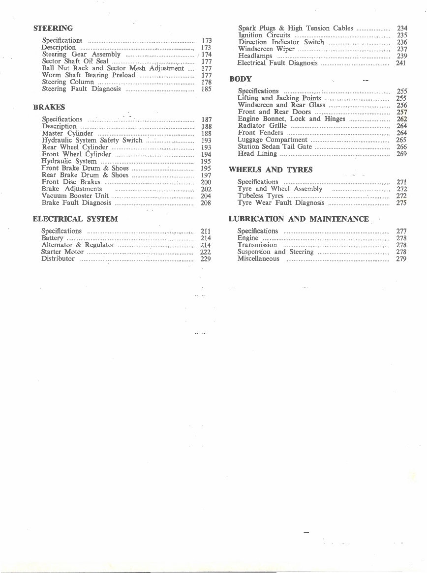
STEERING
Speci~c~tions .. ... .......... .. .. .. .. .. .. .. .. .. . .. ........ .... .. .. .. .. .. . .. . 173
Qescnptlon .. .. .. .. .. .. .. .......... .. ..... .. .. .. .. .. .. .. .. .. .. .. .. .. .. ....... 173
Steering Gear Assembly ...... ... ........ .. ..................... 174
Sector Shaft Oil Seal .. .... .. .. .. .. . .. . .... .... .......... .... .. ... .. . 177
Ball Nut Rack and Sector Mesh Adjustment .. .. 177
Worm Shaft Bearing Preload .. .. .............. .............. 177
Steering Column .. .... .... .... .. .. .. .. .. .. ... .. . .. .. .. .. . .. .... .... .. . .. 178
Steering Fault Diagnosis .. ....... .. .. .. ..... .... ................ 185
BRAKES
Speci~ca.tions .. . .. .. . .. .. .. .. . .. .. .. .. .. .. ...... .. .. .. .. .. ... .. .. .. . .. .... . 187
Descnptlon ..... .. .. .. ...... ..... ... ..... .......... .......... ... ...... .. ... .. 188
Master Cylinder .. .... . .. .. .. .. .. .. .. .. .. .. .. .. .. .. .. .. .. .. .. . .... . .. . .. 188
Hydraulic System Safety Switch ..... .. .. ........ ........ ... 193
Rear Wheel Cylinder ................................................ 193
Front Wheel Cylinder ........ .. .... ... ... .......................... 194
Hydraulic System ...................................... .. .. .. .......... 195
Front Brake Drum & Shoes .................................... 195
Rear Brake Drum & Shoes .................................... 197
Front Disc Brakes ......... ......... .... .. ... ..... ....... ... :......... 200
Brake Adjustments .. .. .. .. .. .. ... .. .. .. .. . .. .. .. .. . .. ... .. .. .. .. 202
Vacuum Booster Unit ............ ... ........ .. ........... .. ... ... .... 204
Brake Fault Diagnosis ... .. ...... .. ...... .. ... .. .. ........ ... ....... 208
ELECTRICAL SYSTEM
Specifications ................................................. ... .. .... .. ..
Battery .................................................................... ..... .
Alternator & Regulator ....... .. .. ............ .. ......... ..... ... ..
Starter Motor ........ ........ .............. .. .. ... .. ....... ........ .... .. ..
Distributor ................................................................ ..
211
214
214
222
229
Spa.r~ Plu~s ~ High Tension Cables .................... 234
Igmtlon Clrcmts ............................................. .. ... .. .... 235
Direction Indicator Switch ...... .............................. 236
Windscreen Wiper .... ..... ...... ...... .. .. .. .. .... ...... .. .... ... ... ... 237
Headlamps ............. ............. ....... .. .. ......... ..... .... ........... 239
Electrical Fault Diagnosis ..... ................... .. ............. . 241
BODY
Specifications .................................... ......... ..... ... ... ... ... 255
Lifting and Jacking Points ...................................... 255
Windscreen and Rear Glass ..... .. .. .. ........ .. .. .. ..... .. .. .. 256
Front and Rear Doors .......... ........ .... .... .. . .. .. ........ ... 257
Engine Bonnet, Lock and Hinges ........ .. .... . .. .. .. . .. 262
Radiator Grille .. . .. .. .. . .. .. .... . .. .. .. .. .. .. .. .. .... .. .. ..... .. .. ... . .. 264
Front Fenders ...... ... ........ .... ....................................... 264
Luggage Compartment ..... ......................................... 265
Station Sedan Tail Gate ........ ..... .. .......... .. .... ............. 266
Head Lining .. . .. .. .. .. .. .. .. .. .. .. ... .. .. .... .... .. . .. . .... .. ............. 269
WHEELS AND TYRES
Specifications ....... .. ..... ............ .............. ... ...... .. .... ....... 271
Tyre and Wheel Assembly .... .... ........ .. ......... ..... .. 272
Tubeless Tyres ............................................................ 272
Tyre Wear Fault Diagnosis .... ....... .. .......... ... .... ...... 275
LUBRICATION AND MAINTENANCE
Specifications .. .. ... .. ........ ..... ...... .. ... .... .. .......... ...... ... ... .
~~;~~~i~~i~~·· ··::::::::::::::::::::::::: : : :::::::::::::::::::::::::::::::::::
Suspension and Steering ........................................ ..
Miscellaneous ........... .. ... ... ... .. .. .. ........ ...... ......... ... ... .. .
277
278
278
278
279

Type ....
Bore diameter
Stroke ... .
Capacity .. .
Compression ratios
Compression pressure at cranking speed
Maximum variation between cylinders
Maximum bhp at engine rpm :
8.2: I cr
8.4: I cr
9.2: I cr
RAC rating
Maximum torque (8.2: I and 8.4: I cr)
9.2: I cr .
Firing order
Type .......... .
Combustion chamber type
Valve seat angle
Valve seat width:
Inlet
Exhaust . ..
Valve seat run-out, maximum
Cylinder head gasket compressed thickness
Head diameter:
Inlet · ...
Exhaust ..
Stem diameter:
Inlet
Exhaust
Stem to guide clearance:
Inlet
Exhaust
ENGINE
SPECIFICATIONS
CYLINDER HEAD
VALVES
7
6 cyl-in line-ohv
3.401"
4.125"
225 cu in
8.2: 1 early, 8.4:1 later.
VF SERIES
8.4: 1 Standard
9.2 : 1 High compression
7.5:1 Low compression
110-140 psi at 130 rpm
125-155 psi at 130 rpm
(9 .2: 1 engines)
20 psi
145 at 4,400
145 at 4000
160 at 4500
27.7 hp
215 ft/lb at 2400 rpm
220 ft/lb at 2500 rpm
1-5-3-6-2-4
Cast iron with integral valve guides
Wedge shape
45°
.080" ± .01 0"
.050" ± .0 I 0"
.002"
.022"
1.62 0" ± .005"
1.360" ± .005"
.373" + .000"
.001"
.372" + .000"
.001 ""
.001" + .002"
.000"
. 002'' +
.002" .
.000"
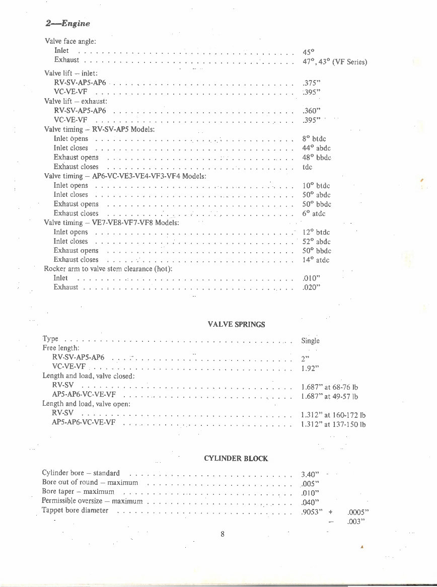
2-Engine
Valve face angle:
Inlet
Exhaust . . .
Valve lift - inlet :
RV-SV-AP5-AP6
VC-VE-VF ...
Valve lift - exhaust:
RV-SV-AP5-AP6
VC-VE-VF ...
Valve timing - RV-SV-AP5 Models :
Inlet 6pens . .
Inlet closes . .
Exhaust opens
Exhaust closes
Valve timing- AP6-VC-VE3-VE4-VF3-VF4 Models:
Inlet opens . .
Inlet closes . .
Exhaust opens
Exhaust closes
Valve timing - VE7-VE8-VF7-VF8 Models:
Inlet opens . .
Inlet closes ..
Exhaust opens
Exhaust closes
Rocker arm to valve stem clearance (hot):
Inlet
Exhaust . .... . .... .. · . . . .
Type .... . .. .
Free length:
RV-SV-AP5-AP6
VC-VE-VF . ...
Length and load, valve closed:
RV-SV ........ .
AP5-AP6-VC-VE-VF ..
Length and load, valve open:
RV-SV ...... .
AP5-AP6-VC-VE-VF ..
Cylinder bore - standard
Bore out of round -maximum
Bore taper - maximum
Permissible oversize - maximum
Tappet bore diameter ... ..
VALVE SPRINGS
CYLINDER BLOCK
8
45°
47° , 43° (VF Series)
.375"
.395"
.360"
.395"
8° btdc
44° abdc
48° bbdc
tdc
10° btdc
50° abdc
50° bbdc
6° atdc
12° btdc
52° abdc
50° bbdc
14° atdc
.0 I 0"
.020"
Single
2"
1.92"
1.687" at 68-76 lb
1.687" at 49-57 lb
1.312" at 160-172lb
1.312"at 137-1501b
3.40"
.005"
.0 I 0"
. 040"
.9053" + .0005"
. 003"
A
'
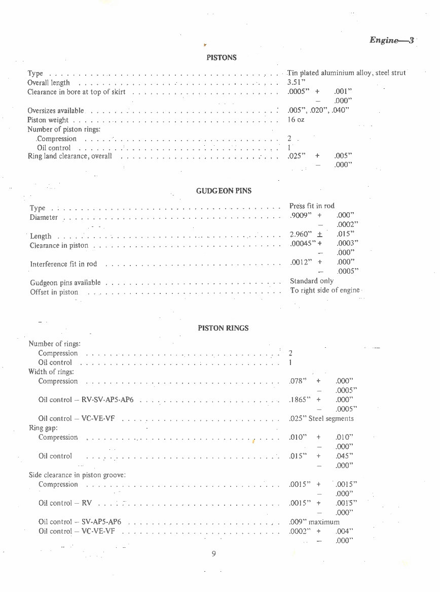
Type ............. .
Overall length . . . . . . . . .
Clearance in bore at top of skirt
Oversizes available . . . .
Piston weight . . . . . .
Number of piston rings:
.Compression
Oil control .....
Ring land clearance, overall
Type ..
Diameter
Length .
Clearance in piston
Interference fit in rod
Gudgeon pins available
Offset in piston
Number of rings:
Compression
Oil control
Width of rings:
Compression
Oil control- RV-SV-AP5-AP6
Oil control- VC-VE-VF
Ring gap :
Compression
Oil control
Side clearance in piston groove:
Compression . . . . .
Oil control - RV
Oil control - SV-AP5-AP6
Oil control - VC-VE-VF .
tr
PISTONS
GUDGEON PINS
PISTON RINGS
9
Engine--3
Tin plated aluminium alloy, steel strut
3.51"
.0005" + .001"
.000"
.005", .020", .040"
16 oz
2
I
.025" + .005"
.000"
Press fit in rod
.9009" + .000"
2.960" ±
.00045" +
.0012" +
Standard only
.0002"
.01 5"
.0003"
.000"
.000"
.0005"
To right side of engine
2
.078" +
.1865" +
.000"
. 0005"
.000"
. 0005"
.025" Steel segments
.010" +
.01 5" +
.0015" +
.001 5" +
.010"
. 000"
.045"
. 000"
.001 5"
.000"
. oor5"
.000"
. 009" maximum
.0002" + . 004"
. 000"
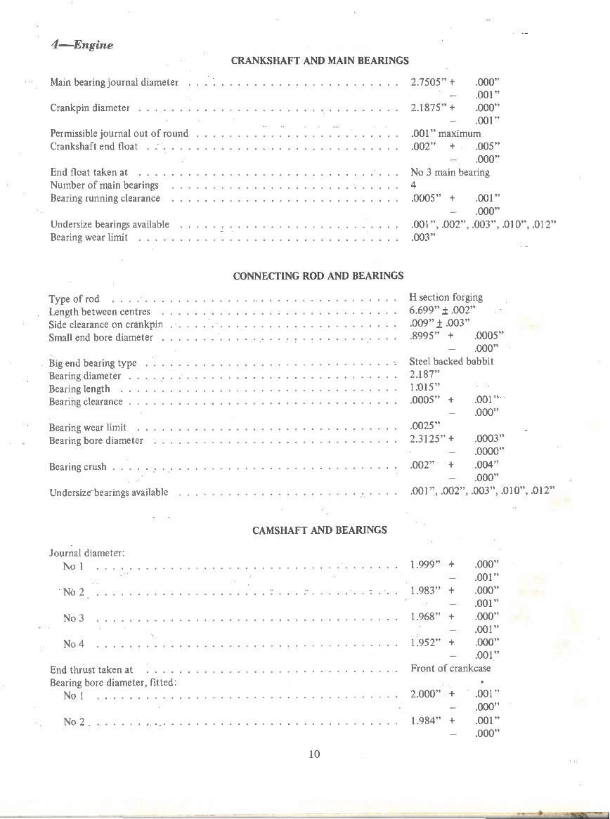
4-Engine
Main bearing journal diameter
Cr ankpin di ameter . . . . . .
Permissible journal out of round
Crankshaft end float
End float taken at .
Number of main bearings
Bearing running clearance
Und ersize bearings available
Be aring wear limit .....
Type of rod .. .... .
Length between centres .
Side clearance on crankpin
Small end bore diameter
Big end bearing type
Bearing diameter
Bearing length .
Bearing clearance
Bearing wear limit
Bearing bore diameter
Bearing crush . ....
Undersize bearings available
Journal diameter:
1\ o 1
No 2
No 3
No 4
End thrust taken at
Bearing bore diameter, fitted:
No I
No 2
CRANKSHAFT AND MAIN BEARINGS
CONNECTING ROD AND BEARINGS
CAMSHAFT AND BEARINGS
10
2.7505" +
2.1875" +
.000"
.001"
. 000"
.001"
.001" maximum
.002" + . .005"
. 000"
No 3 main bearing
4
.0005" + . 001"
.000"
. 001 " , .002", . 003", .010", .012"
. 003"
H section forging
6.699" ± .002"
. 009" ± . 003"
.8995" + . 0005"
.000"
Steel backed babbit
2.187"
1:015"
.0005" + . 001"
. 0025"
2.3125" +
.002" +
.000"
.0003"
.0000"
. 004"
. 000"
.001 ", .002", .003" , .010", .012"
1.999,.,
+ .000"
.001 "
1.983" + .000"
. 001"
1.968" + .000"
. 001"
1.952" + .000"
.001"
Front of crankcase
2.000" + . 001"
.000"
1.984" + .001"
.000"
'
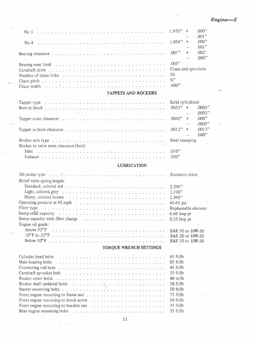
No 3
No4
Bearing clearance
Bearing wear limit
Camshaft drive . .
Number of chain links
Chain pitch .
Chain width .. ...
Tappet type
Bore in block
Tappet outer diameter
Tappet to bore clearance
Rocker arm type . . . .
Rocker to valve stem clearance {hot):
Inlet
Exhaust ..... ....... . .
TAPPETS AND ROCKERS
LUBRICATION
Oil pump type .. . .. ............. .
Relief valve spring length:
Standard, colored red .
Light, colored grey ..
Heavy, colored brown
Operating pressure at 45 mph
Filter type ......... .
Sump refill capacity .... .
Sump capacity with filter change
Engine oil grade:
Above 32°F
l0°F to 32°F
Below l0°F .
Cylinde( head bolts
Main bearing bolts .
Connecting rod nuts
Camshaft sprocket bolt
Rocker cover bolts . . . ..
Rocker shaft pedestal bolts
Starter mounting bolts ...
Front engine mounting to frame nut
Front engine mounting to block screw
Front engine mounting to bracket nut
Rear engine mounting bolts . . . . .
TORQUE WRENCH SETTINGS
11
1.970" +
1.054" +
.001" +
. 005"
.000"
.001"
.000"
. 001"
.002'
. 000"
Chain and sprockets
50
lh"
.880"
Solid cylindrical
.9053" + .0005"
.9045" +
. 0012" +
Steel stamping
.01 0"
.020"
.0003"
.000"
.0005"
.0013"
.000"
Eccentric rotor
2.296"
2.19.0"
2.390"
45-65 psi
Replaceable element
6.66 Imp pt
8.33 Imp pt
SAE 30 or 10W-30
SAE 20 or 10W-30
SAE 10 or lOW-30
65 ft/lb
85 ft/lb
45 ft/lb
35 ft/lb
40 in/lb
30 ft/lb
50 ft/lb
75 ft/lb
50 ft/lb
35 ft/lb
35 ft/lb
Engine--5
6-Engine
I. DESCRIPTION
The engine is a six cylinder in-line, over-head valve
type and is inclined 30 degrees from the vertical to the
right.
A chrome alloy cast iron cylinder head has wedge
shaped combustion chambers and integral valve guides.
Aluminium tubes in the cylinder head serve as gaskets for
the spark plugs.
Poppet type valves, with single springs are installed on
the cylinder head. The valves are operated by stamped
rocker arms in conjunction with push rods and tappets
actuated by the camshaft.
The rocker arms are positioned on the one piece
rocker shaft by hardened steel spacers used between pairs
of rocker arms and seven rocker shaft brackets on the
cylinder head. The rocker shaft is located in position by
bolts and stamped steel retainers attached to the brackets.
A cast iron cylinder block and integral crankcase is
line bored for the crankshaft main bearings and the
camshaft bearings. A water pump housing is cast in the
forward end of the block. Bores in the block are provided
for the solid cylindrical tappets.
A counter-weighted balanced crankshaft runs in four
main bearings. End thrust is taken at No 3 bearing. The
front end of the crankshaft carries a vibration damper, valve
timing sprocket and pulley for fan and alternator belt drive.
The flywheel is bolted to the flanged rear end.
The camshaft has integral oil pump and distributor
drive gear, and fuel pump eccentric, carries the valve timing
sprocket at its forward end and runs in four bearings. End
thrust is taken on the rear face of the timing sprocket
bearing directly on the front face of the cylinder block.
End thrust of the camshaft occurs only to the rear on
account of the drive reaction at the oil pump and
distributor drive gear and the taper on the cam lobes.
The camshaft and the crankshaft sprocket are
coupled by an endless chain.
The cam ground pistons are tin plated aluminium
alloy with steel strut and have two compression rings and
one oil control ring each. Oil control rings on VC, VE and
VF series are steel segment type.
Bushings in the piston bosses provide bearings for the
gudgeon pins which are a press fit in H section forged
connecting rods. The gudgeon pins are offset to the right
side of the engine.
Big end bearings are steel backed babbit shell type.
An eccentric rotor type oil pump is mounted
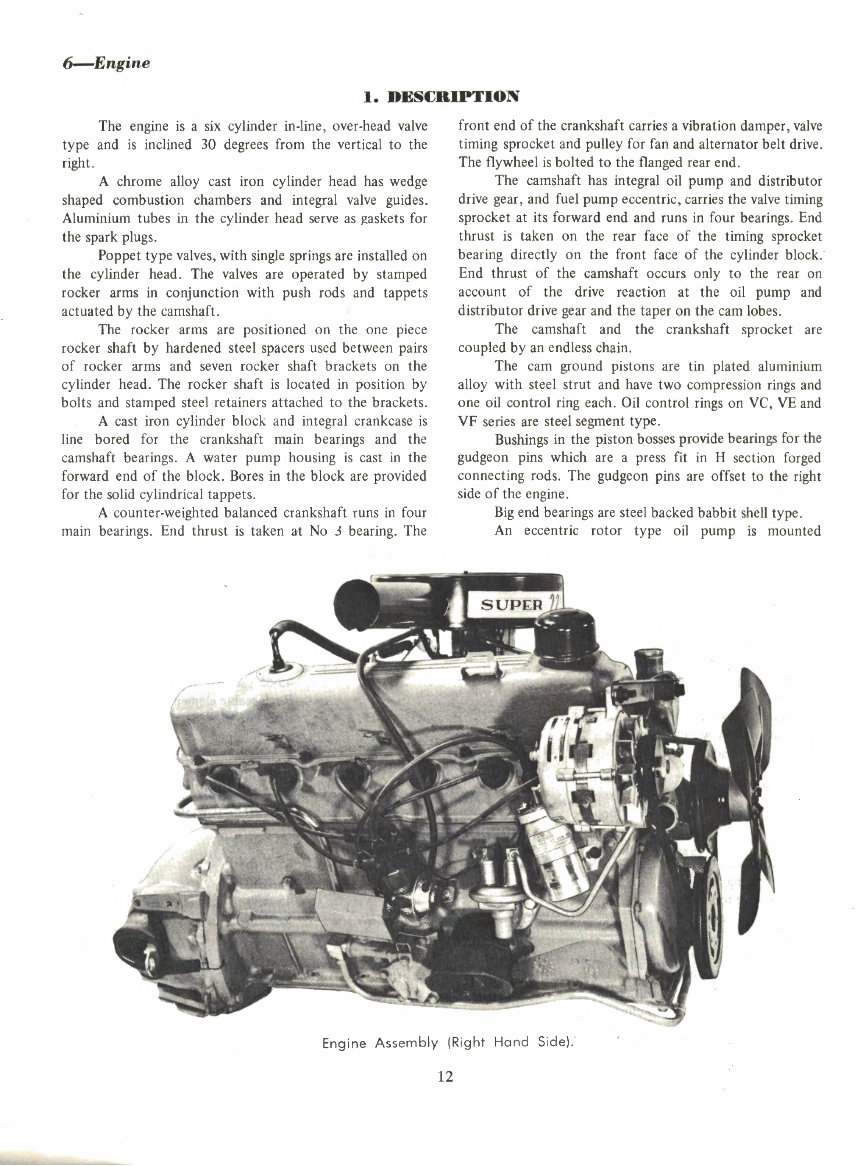
Engine Assembly (Right Hand Side) .'
12
Engine--7
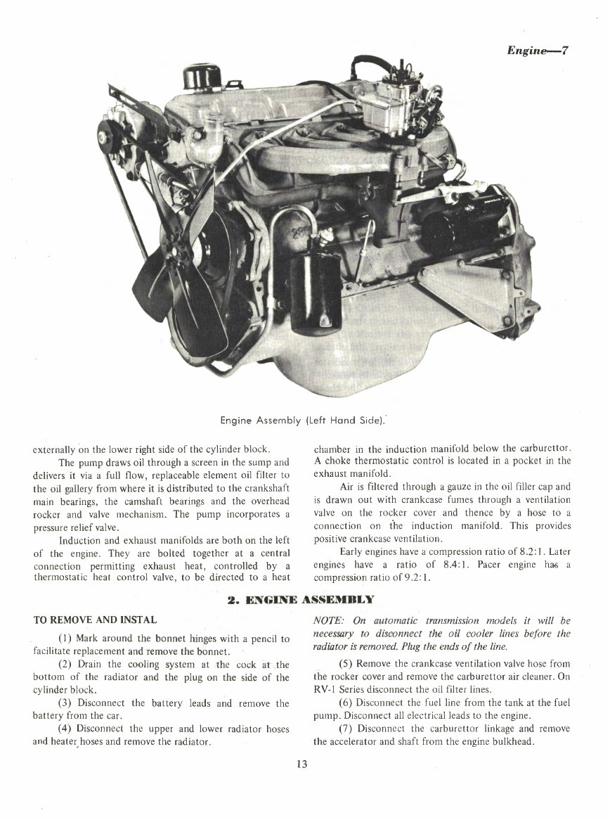
Engine Assembly (Left Hand Side) .'
externally on the lower right side of the cylinder block.
The pump draws oil through a screen in the sump and
delivers it via a full flow, replaceable element oil filter to
the oil gallery from where it is distributed to the crankshaft
main bearings, the camshaft bearings and the overhead
rocker and valve mechanism. The pump incorporates a
pressure relief valve.
Induction and exhaust manifolds are both on the left
of the engine. They are bolted together at a central
connection permitting exhaust heat, controlled by a
thermostatic heat control valve, to be directed to a heat
chamber in the induction manifold below the carburettor.
A choke thermostatic control is located in a pocket in the
exhaust manifold.
Air is filtered through a gauze in the oil filler cap and
is drawn out with crankcase fumes through a ventilation
valve on the rocker cover and thence by a hose to a
connection on the induction manifold. This provides
positive crankcase ventilation.
Early engines have a compression ratio of 8.2: I. Later
engines have a ratio of 8.4 : I. Pacer engine h~ a
compression ratio of 9.2: I.
2. ENGINE ASSEMBLY
TO REMOVE AND INSTAL
(I) Mark around the bonnet hinges with a pencil to
facilitate replacement and remove the bonnet.
(2) Drain the cooling system at the cock at the
bottom of the radiator and the plug on the side of the
cylinder block.
(3) Disconnect the battery leads and remove the
battery from the car.
(4) Disconnect the upper and lower radiator hoses
and heater, hoses and remove the radiator.
13
NOTE: On automatic transmission models it will be
necessary to disconnect the oil cooler lines before the
radiator is removed. Plug the ends of the line.
(5) Remove the crankcase ventilation valve hose from
the rocker cover and remove the carburettor air cleaner. On
RV-1 Series disconnect the oil filter lines.
( 6) Disconnect the fuel line from the tank at the fuel
pump. Disconnect all electrical leads to the engine.
(7) Disconnect the carbure ttor linkage and remove
the accelerator and shaft from the engine bulkhead.
8-Engine
(8) Disconnect the exhaust pipe from the manifold
and remove the exhaust pipe and silencer assembly.
(9) Jack up the car and support on stands.
(10) On manual transmission rnodels - Drain the
transmission, remove the clutch torque shaft and remove
the transmission as outlined in MANUAL TRANSMISSION
- TO REMOVE AND INSTAL
(II) On automatic transmission models - Drain the
convert -e r and transmission and remove the assembly as
outlined in AUTOMATIC TRANSMISSION - TRANS-
MISSION ASSEMBLY- TO REMOVE.
NOTE: Procedures (I 0) or ( 11) as described will cover
removal of all associated connections, linkages and
components.
(12) Support the rear of the engine using the special
fixture and remove the engine rear support crossmember.
(13) Lower the vehicle and remove stands.
(14) Using a suitable sling and lifting tackle take up
the weight of the engine and remove the special engine
support fixture used at (12) above.
(15) Remove the front engine mounting bolts and
raise the engine at an angle with the front higher than the
rear and manoeuvre it clear through the bonnet opening.
Installation is a reversal of the removal procedure
with attention to the following points:
The front engine mounting bolts should be torqued
to 85 ft/lb after the full weight of the engine and
transmission is taken on the mountings.
Check the procedures for installing manual or
automatic transmission, as applicable, in the appropriate
sections.
3. CYLINDER HEAD
TO REMOVE AND INSTAL
(1) Drain the cooling system at the lower radiator
tank cock and the plug on the side of the cylinder block.
(2) Remove the air cleaner, disconnect the choke
control cable and accelerator linkage at the carburettor.
(3) Disconnect the fuel pipes at the carburettor and
fuel pump, and the vacuum pipes at the carburettor and
distributor.
(4) Remove the high tension wires from the
distributor and coil and remove the distributor cap.
Remove the plugs.
13
9 5
10
6
2
(5) Disconnect the heater hose and the clamp holding
the by-pass hose.
(6) Disconnect the water temperature sending unit
lead.
(7) Disconnect the exhaust pipe from the exhaust
manifold, undo the nuts securing the manifolds to the
cylinder head and remove both manifolds and carburettor
as an assembly.
(8) Remove the crankcase ventilation valve hose from
the rocker cover and remove the rocker cover.
In order to remove the rocker cover proceed as
follows when an air conditioner is installed :
3 7 11
4 12
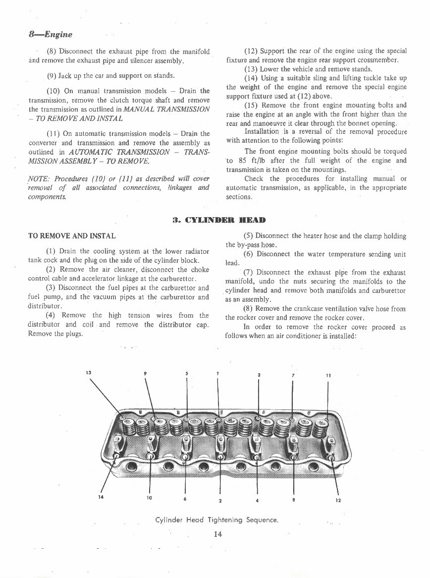
Cylinder Head Tightening Sequence.
14
You're Reading a Preview
What's Included?
Fast Download Speeds
Online & Offline Access
Access PDF Contents & Bookmarks
Full Search Facility
Print one or all pages of your manual
$27.99
$36.99
Viewed 99 Times Today


Secure transaction
What's Included?
Fast Download Speeds
Online & Offline Access
Access PDF Contents & Bookmarks
Full Search Facility
Print one or all pages of your manual
$27.99
$36.99
This comprehensive workshop manual and spare parts catalogue is designed for the Chrysler Valiant VC model vehicles. Whether you are a home workshop mechanic or a professional technician, this manual will assist you in maintaining your Chrysler Valiant with its easy step-by-step instructions and numerous diagrams.
It covers the following Chrysler Valiant models:
- VC
The manual includes information on the following engines and transmissions:
- Engines
- Slant 6 - 225
- 273-V8
- Transmissions
- Torqueflite
The topics covered in this Chrysler Valiant manual include:
- Fully bookmarked & interactive index
- Engine
- Cooling System
- Fuel System
- Clutch
- Manual Transmission
- Automatic Transmission
- Rear Axle
- Front Suspension
- Rear Suspension
- Steering
- Brakes
- Electrical System
- Body
- Wheels & Tyres
- Lubrication & Maintenance
Additionally, it includes a spare parts catalogue.


