2014 Chrysler Town & Country Service & Repair Manual
What's Included?
Lifetime Access
Fast Download Speeds
Online & Offline Access
Access PDF Contents & Bookmarks
Full Search Facility
Print one or all pages of your manual
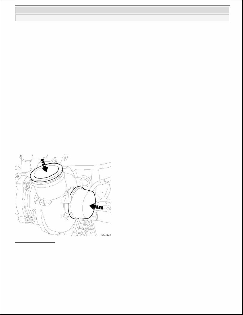
ENGINE 2.8L Diesel - Service Information - Grand Caravan, Town & Country,Grand Voyager DESCRIPTION DESCRIPTION The 2.8L (2776cc) four-cylinder "common rail" direct injection engine is an in-line overhead valve design. The engine utilize a cast iron cylinder block. The engine has a one piece aluminum cylinder head with four valves per cylinder and dual overhead cam shafts. The 2.8L is turbocharged, intercooled and also equipped with a EGR cooler. The identification stamp for the 2.8L is located on the right side of the engine block, below the turbocharger. The engine code label is located on the front timing cover and is the same as the engine I.D. and serial number. There is also a fuel system label on the front timing cover used for fuel system identification during ECM programming. STANDARD PROCEDURE DUST COVERS AND CAPS Fig. 1: Covers/Caps Courtesy of CHRYSLER LLC Due to the high amounts of failures cased by dust, dirt, moisture and other foreign debris being introduced to the engine during service. Covers or caps are needed to reduce the possible damage that can be caused or created. ENGINE 2.8L Diesel NE 2.8L Diesel - Service Information - Grand Caravan, Town & Country 2008-2016 CHRYSLER TOWN & COUNTRY,GRAND CARAVAN,GRAND VOYAGER
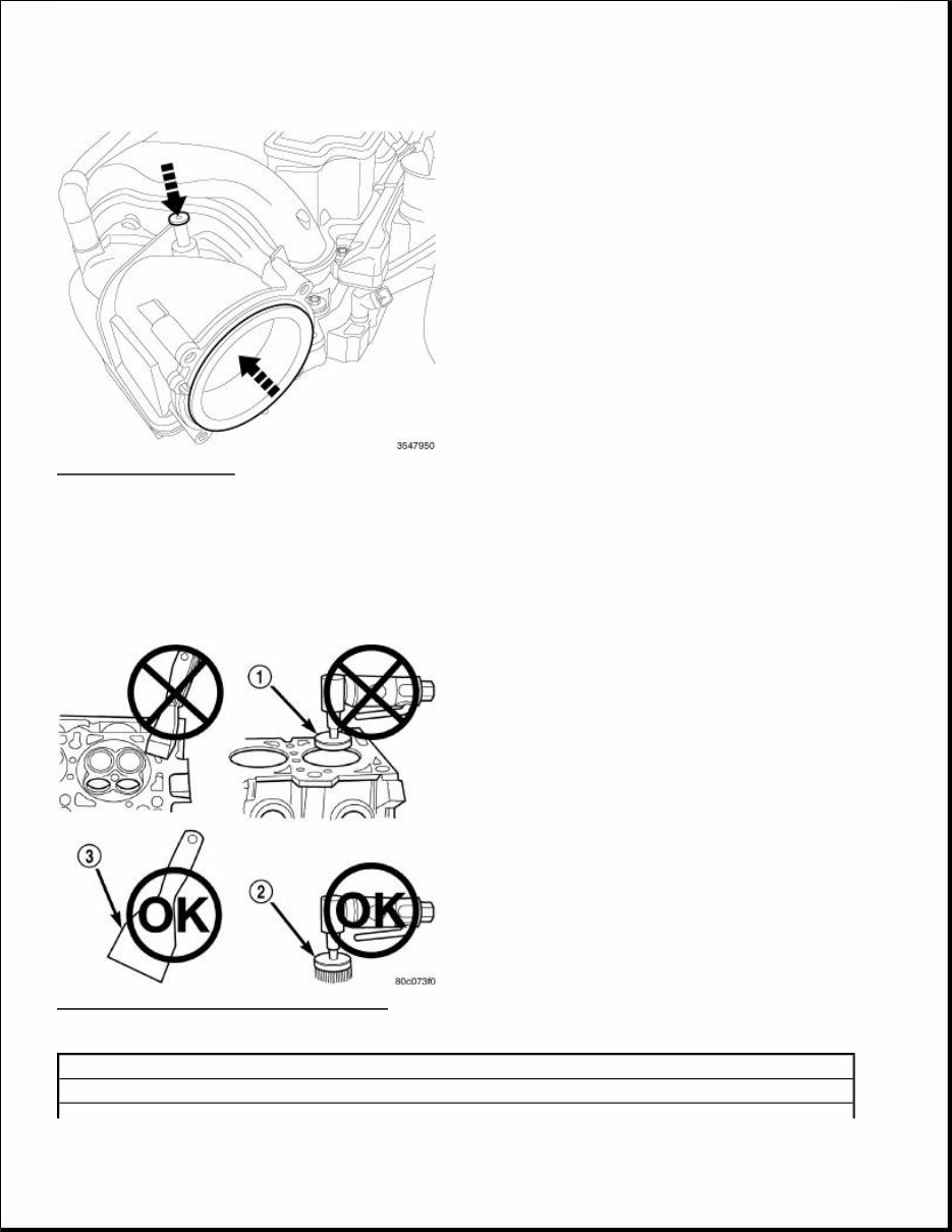
Fig. 2: Opening Cover Courtesy of CHRYSLER LLC Covers over openings will reduce any possibilities for foreign materials to enter the engine systems. Using miller tool (special tool #10368, Set, Universal Protective Cap), Select the appropriated cover needed to the procedure. ENGINE GASKET SURFACE PREPARATION Fig. 3: Preparing Engine Gasket Surfaces Courtesy of CHRYSLER LLC 1 - ABRASIVE PAD 2 - 3M ROLOC™ BRISTLE DISC
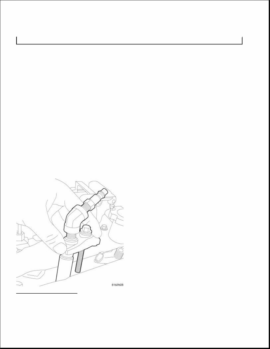
To ensure engine gasket sealing, proper surface preparation must be performed, especially with the use of aluminum engine components and multi-layer steel cylinder head gaskets. Never use the following to clean gasket surfaces: Metal scraper Abrasive pad or paper to clean cylinder block and head High speed power tool with an abrasive pad (1), 3M Roloc™ Bristle Disc (2), or a wire brush (3) Only use the following for cleaning gasket surfaces: Solvent or a commercially available gasket remover Plastic scraper Sealing surfaces must be free of grease or oil residue. Clean surfaces with Mopar® brake parts cleaner (or equivalent) COMPRESSION TEST Fig. 4: Compression Tester Courtesy of CHRYSLER LLC 1. Warm up the engine to operating temperature (approximately 80 degrees C). 3 - PLASTIC SCRAPER NOTE: Multi-Layer Steel (MLS) head gaskets require a scratch free sealing surface.
2. Shut off the engine. 3. Disable the low pressure fuel pump. 4. Remove the fuel injectors. Refer to INJECTOR(S), FUEL, REMOVAL . 5. Cranks the engine with the starter to remove combustion residue in the cylinders. 6. Install the (special tool #VM.10010, Adapter, Compression Test) into the fuel injector bore of the cylinder to be tested. Install the fuel injector retainer, bolt and securely tighten. 7. Test compression pressure by cranking the engine with the starter for at least eight revolutions. 8. Measure the pressure in all of the cylinders. 9. Remove the (special tool #VM.10010, Adapter, Compression Test). 10. Install the fuel injectors. Refer to INJECTOR(S), FUEL, INSTALLATION . SPECIFICATIONS ENGINE INFORMATION Cylinder compression Difference Between Cylinders 10 Bar (145 psi) 2.8L Engine Specifications Engine 2.8L RT Engine Type 2.8L - 16 Valves Displacement 2777 cc Bore 94.00 Stroke 100.05 Power (VGT) 120 kW (177CV) @ 3800 RPM Torque (ATX) 460 N.m @ 1800RPM Cylinders 4 In line Injection Order 1-3-4-2 Compression Ratio 17.0:1 Vacuum at idle 680 mm/HG (27.5 In/HG) Idle Speed (ATX) 765 +/- 50 RPM Maximum RPM in Gear 4500 RPM Maximum RPM in neutral ATX 2800 Belt tension Automatic Belt Tensioner Thermostat opening 80°C +/- 2°C Generator Rating Denso 12V-220A Glow Plug 4.4V Emissions Level EU4 Block configuration/Material Open/Cast Iron Cylinder Head Dual Overhead Cam Timing System Belt
Fuel System CP3.2+ 1, 600 bar Fuel Pump, Piezo Injectors Fuel Supply Electric Fuel Pump In the Fuel Tank Electronic Control Unit EDC 16 Timing System Belt Driven DOHC Overhead Camshaft Air Intake Dry Filter With turbocharger and Charge Air Cooler Fuel System Direct Fuel Injection Common Rail System Emission devices Cooled EGR (pneumatic) Electric Intake Throttle Fast Metallic Glow plugs Combustion Cycle 4 Stroke Cylinder Compression Difference Between Cylinders 10 bar (145 psi) Cooling System Water Cooling Pressure Cap Setting 14 psi Turbocharger Single VGT with REA Intake Ports Aluminum heads with traditional dual side intake and exhaust ports. One intake port is helical and the other has a directed entry. Crankshaft 8 Counterweights with an incorporated balance shaft gear. Camshafts 2 overhead camshafts with axial front bearings and identical camshaft caps, finger followers, and hydraulic lifters. Intake AND Exhaust Valves Flat with fire deck face. Intake Manifold Aluminum, with Cast-in EGR passages, intake mixer, vacuum actuated EGR valve, electric intake throttle and a U-type EGR cooler Lubrication Pressure Lubricated By Rotary Pump Minimum Oil Pressure (warm) 0.7 BAR (10 psi) at idle / 2.5 BAR (36 psi) at 3800 RPM Engine Rotation Clockwise Viewed From Front Cover 2.8L Engine Specifications Cylinder Head Cylinder head height 135.5 mm (5.334 in.) Cylinder head flatness deformation tolerance 0.075 mm (0.003 in.) Cylinder Head Gasket Thickness 0 Hole 1.10 mm (0.043 in) 1 Hole 1.20 mm (0.047 in) 2 Holes 1.30 mm (0.051 in) Intake Manifold Intake manifold flatness deformation tolerance 0.15 mm (0.006 in.) Exhaust Manifold Exhaust manifold flatness deformation tolerance 0.1 mm (0.004 in.) Tappets Hydraulic tappet outside diameters 11.994 mm +/- 0.06 mm (0.472 in +/- 0.002)
Valves Intake valve face angle 45°30' Exhaust valve face angle 45°30' Intake Valve Head Diameter 32 mm (1.25 in.) Exhaust Valve Head Diameter 29.4 mm (1.15 in.) Intake Valve Stem Diameter 5.97 mm (0.235 in.) Exhaust Valve Stem Diameter 5.96 mm (0.235 in.) Intake Valve Guide Stem Clearance Min 0.030 mm (0.0012 in.) Max 0.060 mm (0.0024 in.) Exhaust Valve Guide Stem Clearance Min 0.040 mm (0.0016 in.) Max 0.070 mm (0.0028 in.) Valve Springs Free Length 50.8 mm (2 in.) Closed Valve 38 mm (1.49 in.) Opened Valve 29 mm (1.14 in.) Camshafts Camshaft End Play Min 0.150 mm (0.006 in.) Max 0.350 mm (0.013 in.) Outer Journal Diameter (at crankshaft) 25.95 mm +/- 0.01 mm (1.021 mm +/-.0004 in) Inner Journal Diameter (at cylinder head) 26.00 mm + 0.015 mm (1.027 mm +/-.0006 in) Crankshaft Journal Clearance Max 0.075 mm (0.003 in.) Min 0.030 mm (0.0012 in) Connecting Rods Connecting Rod Diameter (Small End) 32 mm (1.26 in.) Connecting Rod Diameter (Large End) 57.563 mm (2.266 in.) Piston Pin Diameter 32 mm (1.26 in.) Length: Mahle Mondial 70.7 mm - 71.00 mm (2.78 in - 2.79 in.) Length: Federal Mogul 74 mm (2.9 in.) Crankshaft End Play 0.1 mm - 0.34 mm (0.004 in. - 0.013 in.) Bearing Selection. Refer to BEARING SELECTION CHARTS . Engine Block Cylinder Bore Internal Diameter 94 mm (3.700 in.) Cylinder Bore Out-Of-Round (Roundness) 0.009 mm (0.0003 in.) Oversized Piston +0.40 mm (+0.015 in.) Fuel System
CRS 3.0 - 1600 Bar (23.206 psi) High Pressure Pump CP3.2+ ECU EDC16CP31 Injectors Piezo CRI 3.0 Glow Plugs Make/Type Bosch / GLP2 Voltage 4.4V Lubrication System Oil Pump Outer Rotor End Play Min 0.01 (0.0004 in.) Max 0.09 (0.0036 in.) Oil Pump Inner Rotor End Play Max 0.01 mm (0.0004 in.) Min 0.09 mm (0.0036 in.) Oil Pump Outer Rotor to Body Diameter Clearance Max 0.130 mm (0.052 in.) Min 0.230 mm (0.0091 in) Oil Pressure Relief Valve Opening Pressure 5 Bar (73 psi) Oil Pressure Valve Spring Free Length 46.8 mm (1.84 in) Minimum Oil Pressure (Warm) at Idle 0.7 Bar (10 psi) at 3800 RPM 2.5 Bar (36 psi) Cooling System Thermostat Opening Temperature 80°C (176°F) Pressure Cap Setting 1.2 Bar (17 psi) Engine Oil Specification Refer to CAPACITIES AND RECOMMENDED FLUIDS, DESCRIPTION . Coolant Specification. Refer to CAPACITIES AND RECOMMENDED FLUIDS, DESCRIPTION . Cylinder Head Gasket Selection Millimeters Inches DISTANCE FROM PISTON AT TDC TO CYLINDER BLOCK 0.300 - 0.399 0.0119 - 0.0158 CYLINDER HEAD
TORQUE SPECIFICATIONS ENGINE BLOCK GASKET THICKNESS 1.10 0.0434 PISTON CLEARANCE 0.700-0.800 0.0276 -0.0315 DISTANCE FROM PISTON AT TDC TO CYLINDER BLOCK 0.400 - 0.499 0.0158 - 0.0197 CYLINDER HEAD GASKET THICKNESS 1.20 0.0473 PISTON CLEARANCE 0.700-0.800 0.0276 -0.0315 DISTANCE FROM PISTON AT TDC TO CYLINDER BLOCK 0.500 - 0.600 0.0197 - 0.0237 CYLINDER HEAD GASKET THICKNESS 1.30 0.0512 PISTON CLEARANCE 0.700-0.800 0.0276 -0.0315 DESCRIPTION N.m Ft. Lbs. In. Lbs. Air Temp/Pressure sensor 12 - 106 Balance Shaft 33 24 - Connecting Rod Caps Refer to ROD, PISTON AND CONNECTING, INSTALLATION . Dipstick Tube (block) 11 - 97 Dipstick Tube (sump) 11 - 97 Front Mount Refer to INSULATOR, ENGINE MOUNT, RIGHT, INSTALLATION , INSULATOR, ENGINE MOUNT, LEFT, INSTALLATION, INSULATOR,
CYLINDER HEAD ENGINE MOUNT, REAR, INSTALLATION and INSULATOR, ENGINE MOUNT, FRONT MOUNT, INSTALLATION . Left Transmission Mount Refer to INSTALLATION - LEFT ENGINE MOUNT . Fuel Quantity Solenoid 11 - 97 Main Bearing Caps Refer to CRANKSHAFT, INSTALLATION . Oil Cooler 12 - 106 Oil Cooler coolant Adapter Tube at Oil Filter Housing Bolt 11 - 97 Oil Cooler Coolant Tube Bolt 15 - 133 Oil Drain Plug 54 40 - Oil Filter Cap 25 18 - Oil Filter Housing Bolts 33 24 - Oil Jet 11 - 97 Oil Pan Refer to PAN, OIL, INSTALLATION . Oil Pan to Transaxle Bolts 60 44 - Oil Pickup Tube 15 - 133 Oil Pressure Sensor 14 - 124 Rear Mount Refer to INSTALLATION - REAR MOUNT . Rear Mount Bracket Refer to BRACKET, ENGINE MOUNT, REAR MOUNT, INSTALLATION . Right Engine Mount Refer to INSTALLATION - RIGHT ENGINE MOUNT . DESCRIPTION N.m Ft. Lbs. In. Lbs. Camshaft Cap 11 - 97 Camshaft Position Sensor 11 - 97 Camshaft Sprocket 80 59 - Charge Air Cooler Clamp - Intercooler Side 25 18 - Charge Air Cooler Clamp - Turbocharger Side 5 - 44 Cylinder Head Bolt Refer to CYLINDER HEAD, INSTALLATION . Cylinder Head Cover 11 - 97 EGR Air Flow Control Valve Bolts 11 - 97 Exhaust Elbow 33 24 - Exhaust Elbow Bracket 33 24 - Exhaust Manifold 36 27 - Exhaust Manifold Heat Shield 33 24 - Front Camshaft Journal 11 - 97 Fuel injector 33 24 - Fuel Injector Tubes at Fuel Injector 28 21 -
FRONT ENGINE REAR ENGINE ACCESSORY DRIVE Fuel Injector Tubes at Fuel Rail 5 + 75° - 44 + 75° Fuel Rail 24 18 - Glow Plugs 14 - 124 High Pressure Fuel Feed Line at Fuel Rail 5 + 75° - 44 + 75° High Pressure Fuel Feed Tube at High Pressure Pump 28 21 - High Pressure Fuel Tube Bracket Bolt 15 - 133 Intake Manifold Nuts 25 18 - Turbocharger 32 24 - Turbocharger Brace Bolts 32 24 - Turbocharger Oil Feed Line at the Engine Block 32 24 - Turbocharger Adapter (oil feed line to engine block connection) 54 40 - Turbocharger Oil Feed Line Banjo Bolt at Turbocharger 24 18 - Turbocharger Oil Return Line 15 - 133 Vacuum Tube 11 - 97 DESCRIPTION N.m Ft. Lbs. In. Lbs. Crankshaft Damper 32 24 - Crankshaft Sprocket 100 + 120° 74 + 120° - Front Engine Cover 33 24 - Front Engine Lifting Bracket 45 33 - High Pressure Fuel Pump 24 18 - High Pressure Fuel Pump Sprocket Nut. 88 65 - Timing Belt Cover (upper) 8 - 71 Timing Belt Cover (inner) 11 - 97 Timing Belt Cover (lower) 8 - 71 Timing Belt Tensioner 28 21 - Water Pump 32 24 - DESCRIPTION N.m Ft. Lbs. In. Lbs. Crankshaft Position Sensor Cover Plate 15 - 133 Crankshaft Position Sensor 11 - 97 Flex Plate (ATX) Bolt Refer to FLEXPLATE, INSTALLATION . Transmission Adapter Plate (allen bolts) 79 58 - Transmission Adapter Plate (hex bolts) 45 33 -
Get your hands on the 2014 Chrysler Town & Country Service & Repair Manual. Whether you're a professional mechanic or a DIY enthusiast, this auto repair manual provides comprehensive instructions and procedures tailored specifically for the 2014 Chrysler Town & Country. Backed by decades of experience in auto repair and body work, including extensive service on luxury models, this manual not only offers detailed repair procedures but also expert advice on resolving car issues. Expect prompt customer support via email, ensuring you fix your car right the first time. Access technical data for Chrysler vehicles with features that cater to various configurations and options available in the Town & Country model.
Auto Repair Manuals are invaluable for immediate car repairs and ensuring the longevity of your vehicle. With a reliable repair manual, you can save money and enjoy the satisfaction of do-it-yourself projects. This manual contains technical data, detailed diagrams, a complete list of car parts, and clear illustrations, making it easy even for novice mechanics to follow the step-by-step guides. It also includes a comprehensive list of accessories to help enhance your engine’s performance.
Designed with the same precision as used by company engineers, this manual covers all essential sections, including maintenance, engine, control system, mechanical, fuel service specifications, and much more. It is compatible with multiple operating systems including Windows Vista 32 and 64, XP, ME, 98, NT, 2000, and Mac, ensuring ease of access. The manual provides complete instructions, illustrations, wiring schematics, and diagrams necessary for effective vehicle servicing and repairs.
This manual is printable, allowing you to take the necessary pages with you to your workshop or directly to your vehicle. You can enlarge and print images as needed for clarity. Easily accessible with Adobe Reader and other standard software on both Windows and Mac, this manual keeps you updated and informed about your vehicle’s repair needs—empowering you to carry out repairs without sole reliance on a mechanic.
Don't miss the opportunity to have all the necessary car information at your fingertips. Embrace the empowerment of DIY car repairs with this comprehensive repair manual designed specifically for the 2014 Chrysler Town & Country.
Maintenance
Engine
Control System
Mechanical
Fuel Service Specifications
Emission Control
Intake & Exhaust Cooling
Lube
Ignition, Starting & Charging
Auto Transmission Clutch
Manual Transmission
Transfer, Propeller Shaft
Drive Shaft
Differential
Axle Suspension
Tire & Wheel
Brake Control
Brake
Parking Brake
Steering Column
Power Steering
Air Condition
Supplemental Restraint System
Seat Belt
Engine Immobilizer
Cruise Control
Wiper & Washer
Door Lock
Meter Audio/Visual
Horn
Windshield/Glass Mirror
Instrument Panel
Seat
Engine Hood/Door
Exterior & Interior
Electrical
Multiplex/Can Communication
And much more...
This auto repair manual is a time-saving solution, providing you with all the necessary Chrysler car information in one place. Enjoy the convenience of browsing through detailed pages and learning how to repair different parts of your 2014 Chrysler Town & Country. It is an empowering and educational tool that allows you to take charge of your vehicle’s maintenance and repairs.
Recently Viewed
5,521,897Happy Clients
2,594,462eManuals
1,120,453Trusted Sellers
15Years in Business
Price:
Actual Price:
2014 Chrysler Town & Country Service & Repair Manual