TRANSAXLE AND POWER TRANSFER UNIT CONTENTS page page 31TH AUTOMATIC TRANSAXLE ............. 1 41TE AUTOMATIC TRANSAXLE ............ 71 POWER TRANSFER UNIT ................ 154 31TH AUTOMATIC TRANSAXLE INDEX page page GENERAL INFORMATION 31TH TRANSAXLE ....................... 2 FLUID LEVEL AND CONDITION ............. 2 SELECTION OF LUBRICANT ............... 3 SPECIAL ADDITIVES ..................... 3 DESCRIPTION AND OPERATION CLUTCHES, BAND SERVOS, AND ACCUMULATOR . 3 FLOW CONTROL VALVES ................. 3 GEARSHIFT AND PARKING LOCK CONTROLS . 4 GOVERNOR ............................ 4 HYDRAULIC CONTROL SYSTEM ............ 3 PRESSURE REGULATING VALVES .......... 3 PRESSURE SUPPLY SYSTEM .............. 3 TORQUE CONVERTER CLUTCH SOLENOID WIRING CONNECTOR ................... 4 TORQUE CONVERTER CLUTCH ............ 3 DIAGNOSIS AND TESTING CLUTCH AND SERVO AIR PRESSURE TESTS . 15 FLUID LEAKAGE-TRANSAXLE TORQUE CONVERTER HOUSING AREA ........... 16 HYDRAULIC PRESSURE TESTS ........... 13 ROAD TEST ........................... 13 THREE SPEED TRANSAXLE DIAGNOSIS AND TESTS ............................... 4 SERVICE PROCEDURES ALUMINUM THREAD REPAIR .............. 17 FLUID AND FILTER CHANGE .............. 17 FLUID DRAIN AND REFILL ................ 17 FLUSHING COOLERS AND TUBES .......... 17 OIL COOLER FLOW CHECK ............... 18 REMOVAL AND INSTALLATION FRONT PUMP OIL SEAL .................. 20 PARK/NEUTRAL STARTING AND BACK-UP LAMP SWITCH ........................ 18 TRANSAXLE AND TORQUE CONVERTER REMOVAL ........................... 19 VEHICLE SPEED SENSOR PINION GEAR .... 18 DISASSEMBLY AND ASSEMBLY ACCUMULATOR-RECONDITION ............ 36 DIFFERENTIAL REPAIR .................. 45 FRONT CLUTCH-RECONDITION ........... 31 FRONT PLANETARY & ANNULUS GEAR- RECONDITION ........................ 34 KICKDOWN SERVO (CONTROLLED LOAD)- RECONDITION ........................ 36 LOW/REVERSE (REAR) SERVO-RECONDITION .. 35 OIL PUMP-RECONDITION ................. 28 OUTPUT SHAFT REPAIR ................. 42 PARKING PAWL ........................ 41 REAR CLUTCH-RECONDITION ............. 32 TRANSAXLE ........................... 20 TRANSFER SHAFT REPAIR ............... 37 VALVE BODY RECONDITION .............. 24 CLEANING AND INSPECTION VALVE BODY .......................... 50 ADJUSTMENTS BAND ADJUSTMENT .................... 51 BEARING ADJUSTMENT PROCEDURES ..... 51 DIFFERENTIAL BEARING ................. 52 GEARSHIFT CABLE ADJUSTMENT .......... 50 HYDRAULIC CONTROL PRESSURE ADJUSTMENTS ....................... 51 OUTPUT SHAFT BEARING ................ 52 THROTTLE PRESSURE LINKAGE ADJUSTMENT ........................ 51 TRANSFER SHAFT BEARING .............. 53 SCHEMATICS AND DIAGRAMS 31TH TRANSAXLE HYDRAULIC SCHEMATIC . . 54 SPECIFICATIONS 31 TH TRANSAXLE SPECIFICATIONS ....... 63 31TH TORQUE SPECIFICATIONS ........... 65 SPECIAL TOOLS SPECIAL TOOLS—31TH AUTOMATIC TRANSAXLE ......................... 66 NS/GS TRANSAXLEAND POWER TRANSFER UNIT 21 - 1
GENERAL INFORMATION 31TH TRANSAXLE NOTE: Safety goggles should be worn at all times when working on these transaxles. This transaxle combines torque converter , three speed transmission, final drive gearing, anddifferen- tial into a front wheel drive system. The identifica- tion markings and usage of the transaxle are charted in Diagnosis and T ests. NOTE: Transaxle operation requirements are differ- ent for each vehicle and engine combination. Some internal parts will be different to provide for this. Therefore, when replacing parts, refer to the seven digit part number stamped on rear of the transaxle oil pan flange. Within this transaxle, there are three primary areas: (1) Main center line plus valve body . (2) Transfer shaft center line (includes governor andparking sprag). (3) Differential center line. (4) Center distances between the main rotating parts in these three areas are heldprecise to main- tain a low noise level. (5) The torque converter , transaxle area, and dif- ferential are housed in an integral aluminum die casting. The differential oil sump is common with the transaxlesump. Separate filling of the differential is NOT necessary . (6) The torque converter is attached to the crank- shaftthrough a flexible driving plate. Cooling of the converter is accomplished by circulating the tran- saxle fluid through a remote cooler . There are two types of coolers used. An oil-to-water type cooler located in the radiator side tank and/or an oil-to air heat exchanger . The torque converter assembly is a sealed unitthat cannot be disassembled. (7) The transaxle fluid is filtered by an internal fil- ter attached to the lower side of the valve body assembly . (8) Engine torque is transmitted to the torque con- verter then, through the input shaftto multiple-disc clutches in the transaxle. The power flow depends on the application of the clutches and bands. Refer to Elements in Use Chart in Diagnosis and T estssec- tion. (9) The transaxle consists of: • Two multiple-discclutches • An overrunning clutch • Two servos • A hydraulic accumulator • Two bands • Two planetarygear sets This provides three forward ratios and a reverse ratio. The common sun gear of the planetary gear sets is connected to the front clutch by a driving shell. The drive shell issplined to the sun gear and front clutch retainer . The hydraulic system consists of an oil pump, and a single valve body which con- tains all of the valves exceptthe governor valves. The transaxle sump and differential sump are both vented through the dipstick. Outputtorque from the main center line is delivered throughhelical gears to the transfer shaft. This gear set is a factor of the final drive (axle) ratio. The shaft alsocarries the gov- ernor andparking sprag. An integral helical gear on the transfer shaft drives the differential ring gear . The final drive gearing is completed with one of two gearratios of 2.98 or 3.19 depending on model and application. FLUID LEVEL AND CONDITION NOTE: The transmission and differential sump have a common oil sump with a communicating opening between the two. The torque converter fills in both the PPark and N Neutral positions. Place the selector lever in PPark to be sure thatthe fluid level check is accurate. The engineshould be running at idlespeed for at least one minute, with the vehicle on level ground. This will assure complete oillevel sta- bilization between differential and transmis- sion. The fluid should be at normal operating temperature (approximately 82 C. or 180 F .). The fluid levelis correct if it is in the HOT region (cross- hatched area)on the dipstick. Low fluid level can cause a variety of conditions because it allows the pump to take in air along with the fluid. As in any hydraulic system, air bubbles make the fluid spongy , therefore, pressures will be low and build up slowly . Improper filling can also raise the fluid level too high. When the transaxle has too much fluid, the gears churnup foam and cause the same conditions which occur with a low fluid level. In either case, the air bubbles can cause overheat- ing, fluid oxidation, and varnishing. This can inter- fere withnormal valve, clutch, and servooperation. Foaming can also result in fluid escaping from the transaxle dipstick where it may be mistaken for a leak. Along with fluid level, it is importanttocheck the condition of the fluid. When the fluid smells burned, and is contaminated with metal or friction material particles, a complete transaxle overhaul is needed. Be sure to examine the fluid on the dipstick closely . 21 - 2 TRANSAXLEAND POWER TRANSFER UNIT NS/GS
If there is any doubt about its condition, drain out a sample for a double check. SELECTION OF LUBRICANT It is importantthatthe proper lubricant be used in these transmissions. Mopar ATF PLUS (Automatic Transmission Fluid-Type 7176) should be used to aid in assuring optimum transmission performance. Flu- ids of the type labeled DEXRON II Automatic Trans- mission Fluid should be used only if the recommended fluid is not available. If more than a small amount of Dexron fluid is used, shudder or shift quality problems may be encountered. It is importantthatthe transmission fluid be maintained atthe prescribed level using the recommended fluids. SPECIAL ADDITIVES Chrysler Corporation does not recommend the addition of any fluids to the transmission, other than fluid listed above. An exception to this policy is the use of special dyes to aid in detecting fluid leaks. The use of transmission sealersshould be avoided, since they may adversely affect seals. DESCRIPTION AND OPERATION TORQUECONVERTER CLUTCH A torque converter clutch isstandard on all vehi- cles. The torque converter clutch is activated only in direct drive and is controlled by theengineelectron- ics. A solenoid on the valve body , is powered by the powertrain control module to activate torque con- verter clutch. HYDRAULIC CONTROL SYSTEM The hydraulic control systemmakes the transaxle fully automatic, and has four important functions to perform. The components of any automatic control system may be grouped into the following basic groups: The pressure supply system, the pressure regulat- ingvalves, the flow control valves, the clutches, and band servos. Taking each of these basic groups or systems in turn, the control systemmay be described as follows: PRESSURE SUPPL Y SYSTEM The pressure supply system consists of an oil pump driven by the engine through the torque converter . The single pump furnishes pressure for all the hydraulic and lubrication requirements. Oil pump housing assemblies are available with prese- lectedpump gears. PRESSURE REGULATING VAL VES The pressure regulating valve controls line pres- sure dependent on throttle opening. The governor valve transmits regulatedpressure to the valve body (in conjunction with vehicle speed) to control upshift anddownshift. The throttle valve transmits regulatedpressure to the transaxle (dependent on throttle position) to con- trol upshift anddownshift. FLOW CONTROL VAL VES The manual valve provides the differenttransaxle drive ranges asselected by the vehicle operator . The 1-2 shift valve automatically shifts the tran- saxle from firstto second or from second tofirst, depending on the vehicle operation. The 2-3 shift valve automatically shifts the tran- saxle from second to third or from third to second depending on the vehicle operation. The kickdown valve makes possible a forceddown- shift from third to second, second tofirst, or third to first (depending on vehicle speed). This can be done by depressing the accelerator pedal pastthe detent feel near wide open throttle. The shuttle valve has two separate functions and performs each independently of the other . The first is providing fast release of the kickdown band, and smooth front clutch engagement when a lift-foot upshift from second to third is made. The second function is to regulate the application of the kick- down servo and band when making third to second kickdown. The by-pass valve provides for smooth application of the kickdown band on 1-2 upshifts. The torque converter clutch solenoid allows for the electronic control of the torque converter clutch. It also disengages the torque converter at closed throt- tle. This is done during engine warm-up, and part- throttle acceleration. The switch valve directs oil to apply the torque converter clutch in one position. The switch valve releases the torque converter clutch in the other posi- tion. CLUTCHES, BANDSERVOS, AND ACCUMULATOR The front and rear clutch pistons, and both servo pistons are moved hydraulically to engage the clutches and apply the bands. The pistons are released by spring tension whenhydraulic pressure is released. On the 2-3 upshift, the kickdown servo piston is released by spring tension and hydraulic pressure. The accumulator controls the hydraulic pressure on the apply side of the kickdown servo during the 1-2 upshift; thereby , cushioning the kickdown band application at any throttle position. NS/GS TRANSAXLEAND POWER TRANSFER UNIT 21 - 3 GENERAL INFORMATION (Continued)
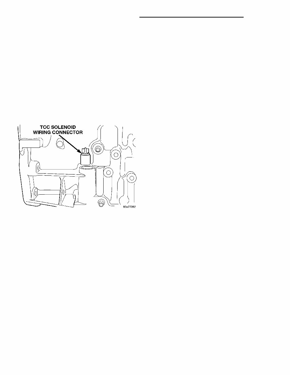
GEARSHIFTAND PARKING LOCK CONTROLS The transaxle is controlled by a lever type gear- shift incorporated within the steering column. The control has six selector lever positions: P (park), R (reverse), N (neutral), and D (drive),2 (second), and 1 (first). The parking lock is applied by moving the selector lever past a gate to the P position. Do not apply the parkinglock until the vehicle has stopped; otherwise, a severe ratchet noise will occur . TORQUECONVERTER CLUTCH SOLENOID WIRING CONNECTOR If wiring connector is unplugged, the torque con- verter will not engage (Fig.1). GOVERNOR The governor may be serviced by removing the transaxle oil pan and valve body assembly . The gov- ernor may be unbolted from the governor support and removed from the transaxle forreconditioning or replacement. When cleaning or assembling the governor , make sure the governor valves move freely in the bores of the governor body . DIAGNOSIS AND TESTING THREE SPEED TRANSAXLE DIAGNOSIS AND TESTS Automatic transaxle malfunctions may be caused by four general conditions: (1) Poor engine performance (2) Improper adjustments (3) Hydraulic malfunctions (4) Mechanical malfunctions Diagnosis of these problems should always begin by checking theeasily accessible variables;fluid level and condition, gearshift cable adjustment, and throt- tle pressure cable adjustment. Then perform a road testto determine if the problem has been corrected or that more diagnosis is necessary . If the problem exists after the preliminary tests and corrections are completed, hydraulic pressure tests should be per- formed 31TH HYDRAULIC TROUBLE CODE CHARTS The following chartsshould be used to helpdiag- nose hydraulicor mechanical faults in the transaxle. Fig. 1 Torque Converter Clutch Solenoid Wiring Connector TCC SOLENOID WIRING 21 - 4 TRANSAXLEAND POWER TRANSFER UNIT NS/GS DESCRIPTION AND OPERATION (Continued)
CONDITION POSSIBLE CAUSES CORRECTION HARSH ENGAGEMENT FROM NEUTRAL TO DRIVE 1. Engine idle speed too high. 1. Set engine curb idle. 2. Valve body malfunction. 2. Inspect valve body and repair. 3. Hydraulic pressure too high. 3. Check fluid pressure at ports. 4. Worn or faulty rear clutch. 4. Replace discs and seals at rear clutch. 5. Engine performance. 5. Set engine to specs. HARSH ENGAGEMENT FROM NEUTRAL TO REVERSE 1. Low reverse band misadjusted. 1. Adjust bands to specs. 2. Engine idle speed too high. 2. Set up engine to specs. 3. Low reverse band worn out. 3. Replace low reverse band. 4. Low reverse band, servo or linkage malfunction. 4. Repair low reverse servo. Adjust reverse band and linkage. 5. Hydraulic pressure too high. 5. Check fluid pressure at ports. 6. Worn or faulty rear clutch. 6. Replace discs and seals at rear clutch. 7. Engine performance. 7. Set engine to specs. DELAYED ENGAGEMENT FROM NEUTRAL TO DRIVE 1. Hydraulic pressure too low. 1. Check fluid pressure at ports. 2. Valve body malfunction. 2. Inspect valve body and repair. 3. Low fluid level. 3. Fill trans. to level. 4. Incorrect gearshift linkage adjustment. 4. Adjust gearshift linkage. 5. Oil filter clogged. 5. Replace oil filter. 6. Faulty oil pump. 6. Replace oil pump. 7. Worn input shaft seal rings. 7. Replace input shaft seal rings. 8. Aerated fluid. 8. Replace trans. fluid. 9. Engine idle speed too low. 9. Set up engine to specs. 10. Worn or faulty rear clutch. 10. Replace discs and seals at rear clutch. Diagnosis Guide NS/GS TRANSAXLEAND POWER TRANSFER UNIT 21 - 5 DIAGNOSIS AND TESTING (Continued)
You're Reading a Preview
What's Included?
Lifetime Access
Fast Download Speeds
Offline Viewing
Access Contents & Bookmarks
Full Search Facility
Print one or all pages of your manual
$36.99
1999 Chrysler/Dodge Town & Country, Caravan and Voyager Workshop Repair Service Manual
This is a comprehensive Service and Repair Manual for the 1999 Chrysler/Dodge Town & Country, Caravan, and Voyager. It covers all models and engines, providing detailed illustrations, exploded diagrams, drawings, and photos to guide you through every service repair procedure. Whether you're a professional mechanic or a DIY enthusiast, this manual is designed to make any repair job easy with step-by-step instructions and pictures covering all areas of repair.
Fixing problems in your vehicle is made easier with this Repair Manual, which contains comprehensive instructions and procedures for addressing issues in your ride. It's a valuable resource for immediate repairs and can save you money by enabling do-it-yourself projects. The manual includes technical data, diagrams, a complete list of car parts, and pictures, making it accessible even for novices. Additionally, it provides a complete list of accessories to enhance your engine's performance.
This Repair Manual for the 1999 Chrysler/Dodge Town & Country, Caravan, and Voyager is compatible with all versions of Windows, Mac, iOS, BB, Android, etc. It is printable and covers a wide range of services including engine overhaul and rebuilding, brakes, sunroof, timing belt replacement, troubleshooting, diagnostics, computer diagnostic trouble tree charts, and much more.
Engine overhaul and rebuilding
Brakes
Sunroof
Timing belt replacement
Trouble codes
Wiring diagrams
Troubleshooting and diagnostics
Computer diagnostic trouble tree charts
Engine performance
Front end and alignment procedures and specifications
Suspension
Transmission removal and installation
Air conditioning service and capacities
Transmission in-car servicing
Computer diagnostic codes
Firing orders
Detailed specifications on every model covered
Factory maintenance schedules and charts
Serpentine belt routings with diagrams
Brake servicing procedures
Driving concerns
Complete torque specifications
U-joint and CV-joint service procedures
Repair procedures
Complete wiring diagrams
Hundreds of illustrations
Vacuum diagrams
This manual is available for instant access, eliminating shipping costs and waiting time for a paper or CD manual to arrive. You can receive this manual today via instant and be confident in your purchase.
Reviews
Q&A
Recently Viewed
5,521,897Happy Clients
2,594,462eManuals
1,120,453Trusted Sellers
15Years in Business
Price:
Actual Price:
1999 Chrysler/Dodge Town & Country, Caravan and Voyager Workshop Repair Service Manual






 Lifetime Access




