2005 Chrysler PT Cruiser (Sedan/Convertible) Service & Repair Manual
What's Included?
Lifetime Access
Fast Download Speeds
Offline Viewing
Access Contents & Bookmarks
Full Search Facility
Print one or all pages of your manual
GROUP TAB LOCATOR Introduction 0 Lubrication & Maintenance 2 Suspension 3 Differential & Driveline 5 Brakes 6 Clutch 7 Cooling 8A Audio/Video 8B Chime/Buzzer 8E Electronic Control Modules 8F Engine Systems 8G Heated Systems 8H Horn 8I Ignition Control 8J Instrument Cluster 8L Lamps 8M Message Systems 8N Power Systems 8O Restraints 8P Speed Control 8Q Vehicle Theft Security 8R Wipers/Washers 8T Navigation/Telecommunication 8W Wiring 9 Engine 11 Exhaust System and Turbocharger 13 Frame & Bumpers 14 Fuel System 19 Steering 21 Transaxle 22 Tires/Wheels 23 Body 24 Heating & Air Conditioning 25 Emissions Control Component and System Index Service Manual Comment Forms (Rear of Manual)
INTRODUCTION TABLE OF CONTENTS page page BODY CODE PLATE DESCRIPTION .......................... 1 FASTENER IDENTIFICATION DESCRIPTION .......................... 2 FASTENER USAGE DESCRIPTION FASTENER USAGE ..................... 5 THREADED HOLE REPAIR ............... 5 INTERNATIONAL SYMBOLS DESCRIPTION .......................... 5 METRIC SYSTEM DESCRIPTION .......................... 5 TORQUE REFERENCES DESCRIPTION .......................... 8 VEHICLE IDENTIFICATION NUMBER DESCRIPTION - VEHICLE IDENTIFICATION NUMBER ............................. 9 VEHICLE CERTIFICATION LABEL DESCRIPTION ......................... 11 E-MARK LABEL DESCRIPTION ......................... 11 VECI LABEL DESCRIPTION ......................... 11 MANUFACTURER PLATE DESCRIPTION ......................... 11 BODY CODE PLATE DESCRIPTION The Body Code Plate (Fig. 1) is located in the engine compartment on the plenum behind the right side struttower (Fig. 2). There are seven lines of information on the body code plate. Lines 4, 5, 6, and 7 are not used to define service information. Informa- tion reads from leftto right, starting with line 3 in the center of the plate to line 1 atthe bottom of the plate. BODYCODE PLATE LINE2 DIGITS 1, 2, AND 3 Paint procedure DIGIT 4 Open Space DIGITS 5THROUGH 7 Primary paint (Refer to 23 - BODY/PAINT - SPECIFICATIONS) for Body Color Codes. DIGIT 8 AND 9 Open Space DIGITS 10 THROUGH 12 Secondary Paint DIGIT 13 AND 14 Open Space DIGITS 15 THROUGH 18 Interior Trim Code DIGIT 19 Open Space Fig. 1 BODY CODE PLATE 1 - PRIMARY PAINT 2 - SECONDARY PAINT 3 - VINYL ROOF 4 - VEHICLE ORDER NUMBER 5 - CAR LINE SHELL 6 - PAINT PROCEDURE 7 - ENGINE 8 - TRIM 9 - TRANSMISSION 10 - MARKET 11 - VIN PT INTRODUCTION 1
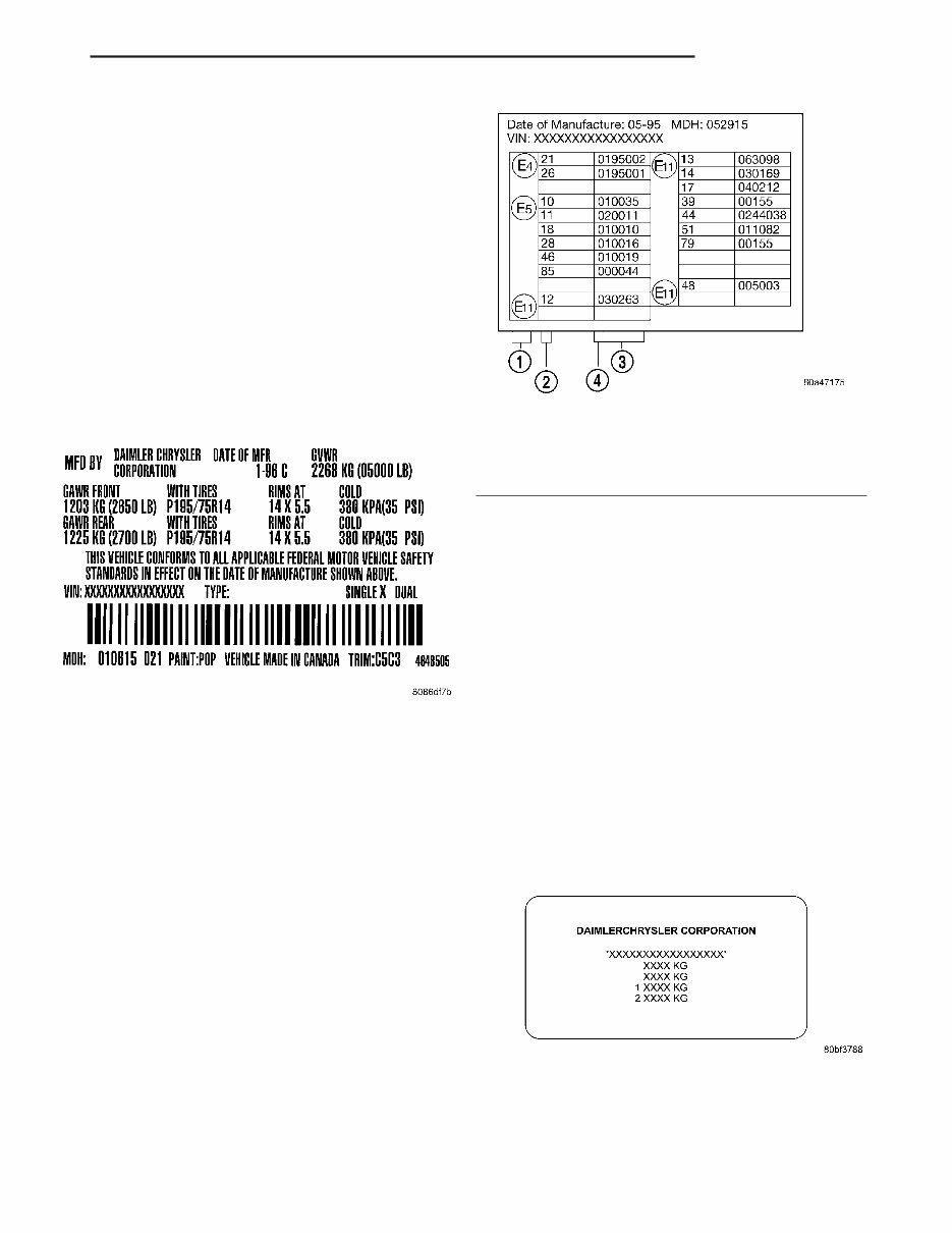
VEHICLE CERTIFICATION LABEL DESCRIPTION A vehicle certification labelis attached to the rear shutface of the driver’s door (Fig.4). This labelindi- cates date of manufacture (month and year), Gross V ehicle Weight Rating (GVWR), Gross Axle Weight Rating (GA WR) front, Gross Axle Weight Rating (GA WR) rear and the V ehicle Identification Number (VIN). The Month, Day and Hour of manufacture is also included. All communications or inquiries regarding the vehicle should include the Month-Day-Hour and V ehicle Identification Number . E-MARK LABEL DESCRIPTION An E-mark Label (Fig. 5) is located on the rear shut face of the driver’s door . The label contains the following information: • Date of Manufacture • Month-Day-Hour (MDH) • V ehicle Identification Number (VIN) • Country Codes • Regulation Number • Regulation Amendment Number • Approval Number VECI LABEL DESCRIPTION All models have a V ehicle Emission Control Infor- mation (VECI) Label. Chrysler permanently attaches the label in the engine compartment. It cannot be removed without defacing information anddestroying the label. The label contains the vehicle’s emission specifica- tions and vacuum hose routings. All hoses must be connected and routed according to the label. MANUFACTURER PLATE DESCRIPTION The Manufacturer Plate (Fig. 6) is located in the engine compartment on the passenger side rear cor- ner of the hood. The plate contains five lines of infor- mation: 1. V ehicle Identification Number (VIN) 2. Gross V ehicle Mass (GVM) 3. Gross Train Mass (GTM) 4. Gross Front Axle Rating (GFAR) 5. Gross Rear Axle Rating (GRAR) Fig. 4 VEHICLE CERTIFICATION LABEL - TYPICAL Fig. 5 E-MARK LABEL 1 - COUNTRY CODE 2 - REGULATION NUMBER 3 - APPROVAL NUMBER 4 - AMENDMENT NUMBER Fig. 6 MANUFACTURER PLATE PT INTRODUCTION 11
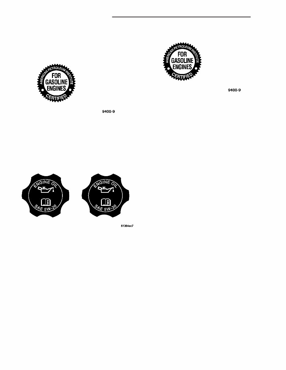
• Association des Constructeurs Européens d’ Automobiles (European Automobile Manufacturers Association) (ACEA) API CERTIFICATION AND LICENSE SYMBOL Use an engine oil that is API Certified (Fig.2) and Licensed to display the certification mark. MOPAR provides engine oils that meet or exceed, Material Standard MS-6395 requirement. SAE VISCOSITY SAE 5W-20 and SAE 5W-30 engine oils are rec- ommended for all operating temperatures. These engine oils are designed to improve low temperaturestarting and vehicle fuel economy . Referto theengine oil filler cap forthe pre- ferred engine oilviscositygrade for each vehi- cle (Fig. 3). SAE viscositygrades are used to specify the correct viscosity oil for an engine. Use only Multi- Viscosity oils such as SAE 5W-20 or 5W-30. These are specified with a dualSAE viscositygrade which indicates the cold (5W) to hot (20, 30) temperature performance range of the oil. ACEA CATEGORIES For countries that use the ACEA European Oil Categories for service fill oils, use engine oils that meet the requirements of ACEAA1/B1, A2/B2, or A3/B3. CONTAINER IDENTIFICATION The Engine Oil Certification Mark was developed and trademarked by the API to refer customers to thoseengine oils preferred by the automobile manu- facturers. Thissymbol means thatthe oil has been certified and licensed by the American Petroleum Institute (API). This certification mark will only be found on the front of the oil containers (Fig.4). Those oils that do not display the “Mark” on the front of the container should not be used. DiamlerChrysler only recommends API Certified engine oils that meetthe requirements of Material Standard MS-6395. Use Mopar or an equivalent oil meeting the specification MS-6395. SYNTHETIC ENGINE OILS There are a number of engine oils being promoted as either syntheticor semi-synthetic. If you chose to use such a product, use only those oils that are cer- tified by the American Petroleum Institute (API) to display the “Certification Mark” and show SAE vis- cosity grade recommended for each vehicle. Follow the service schedule that describes your driving type. ENGINE OIL ADDITIVES/SUPPLEMENTS The manufacturer does notrecommend the addi- tion of any engine oil additives/supplements to the specified engine oil. Engine oil additives/supplements should not be used to enhance engine oil perfor- mance. Engine oil additives/supplementsshould not be used to extend engine oil change intervals. No additive is known to be safe for engine durability and can degradeemission components. Additives can con- tain undesirable materials that harm the long term durability of engines and emission systems by: • Increasing the level of Phosphorus and Sulfur in theengine oil. The API Certified Engine Oils control the Phosphorus and Sulfur contents of the oil to lev- els that reduce the contamination effect on the vehi- cles emission control system. • Altering the viscosity characteristics of the engine oil so that it no longer meets the require- ments of the specified viscositygrade. • Creating potential for an undesirable additive compatibility interaction in the engine crankcase. Fig. 2 API Certification Mark Fig. 3 5W-30 Oil Filler Cap Fig. 4 API Certification Mark 0 - 2 LUBRICATION & MAINTENANCE PT FLUID TYPES (Continued)
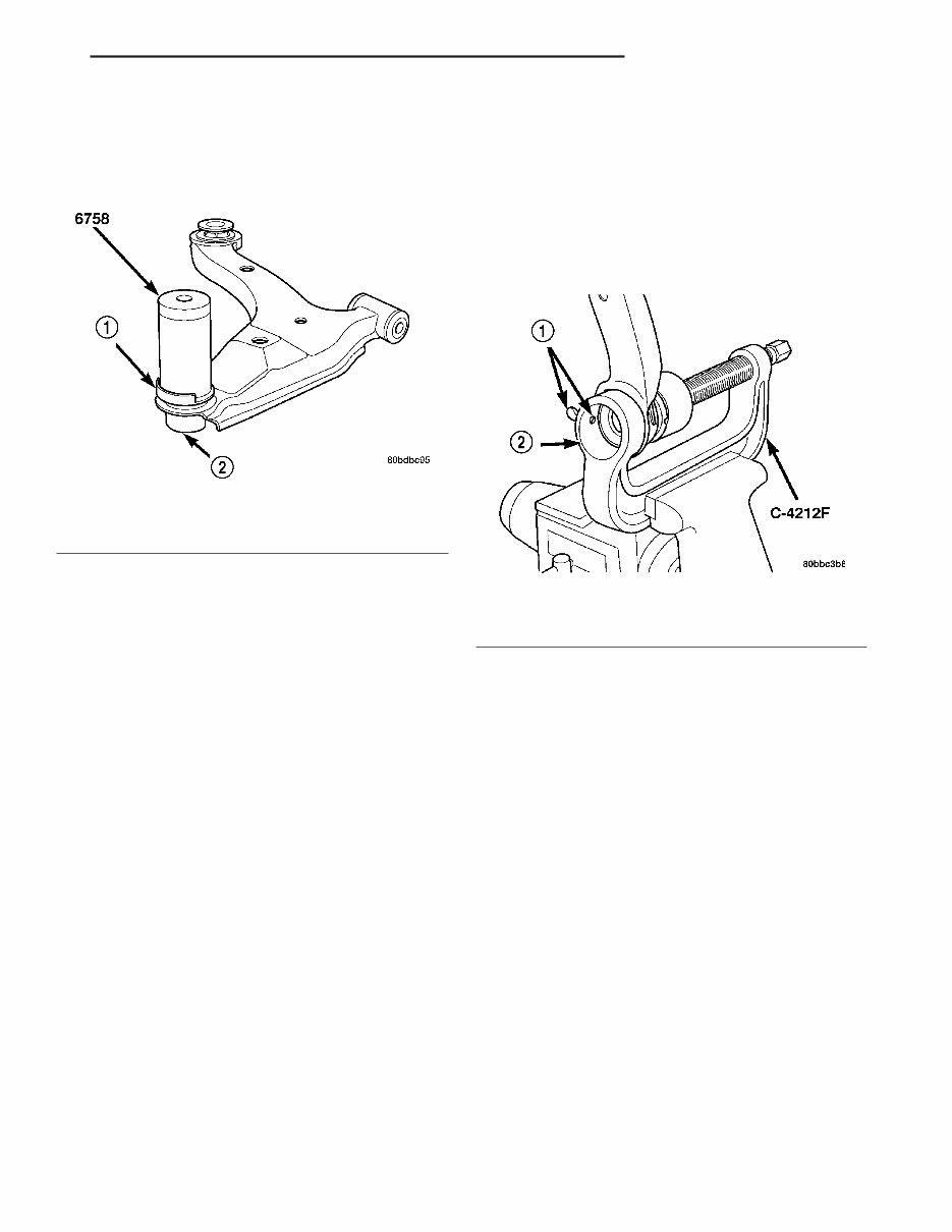
CAUTION: When installing the sealing boot on the ball joint, position the upward lip on the outside perimeter of the seal boot outward, away from the control arm once installed (Fig. 32). It is there to help shield heat from the sealing boot. (6) Place a new ball joint seal boot over the ball joint stud. The upward lip located on the outside perimeter of the seal boot must point outward away from the control arm once installed (Fig. 32). Start the sealing boot over the sides of the ball joint by hand. (7) Position the Installer , Special T ool 6758, over the sealing boot outer diameter asshown (Fig. 32). By hand, apply pressure to the top of the Installer until the seal boot is pressed squarely down against the top surface of lower control arm. (8) Remove the tool. (9) If not already installed, install standard zirc- type grease fitting in ball joint. CAUTION: It is important to lubricate the ball joint before installation of steering knuckle to allow proper venting when the seal is filled. If the ball joint is lubricated after installation to knuckle, dam- age to the seal can occur. (10) Using a hand-operatedpump grease gun, fill the ball joint seal boot with Mopar Multi-Mileage Lube or equivalent until grease pushes out past ball joint stem. Wipe off overfill. (11) Remove standard zirc-type grease fitting and install headless grease fitting from original ball joint to prevent future lubricating. See above Caution. Be sure to properly cleanheadless grease fitting priorto installation. (12) Install the lower control arm. (Refer to 2 - SUSPENSION/FRONT/LOWER CONTROL ARM - INSTALLATION). ASSEMBL Y - LOWER CONTROL ARM (REAR ISOLATOR BUSHING) (1) Back the Ball Joint Press, Special T ool C-4212F , set screw outward so it does not extend out into the cup area (Fig. 33). (2) Startthe isolator bushing into the bottom of the lower control arm bushing bore by hand. Position the bushing so the voids in the rubber are aligned in relationship to the ball joint asshown (Fig. 34). Place the larger void toward the ball joint. (3) Install the Installer , Special T ool 9356-1, on the tip of the Ball Joint Press screw drive. (4) Place the lower control arm upper flange against the cup area of the Ball Joint Press and tighten the screw-drive until the Installer contacts the outer circumference of the bushing (Fig. 35). Make sure the bushing flange sits squarely in the step built into the Installer . (5) Using hand tools, slowly tighten the screw- drive until the bushing bottoms in the lower control arm bushing bore. Do not overtighten the screw- drive; damage to the bushing, arm or tool can result. (6) Back off the screw-drive and remove the con- trol arm from the Ball Joint Press. (7) Install the lower control arm on the vehicle. (Refer to 2 - SUSPENSION/FRONT/LOWER CON- TROL ARM - INSTALLATION) Fig. 32 Seal Boot Installation 1 - SEAL BOOT UPWARD LIP 2 - BALL JOINT Fig. 33 Set Screw Backed Outward 1 - SET SCREW 2 - CUP AREA PT FRONT SUSPENSION 2 - 17 LOWER CONTROL ARM (Continued)
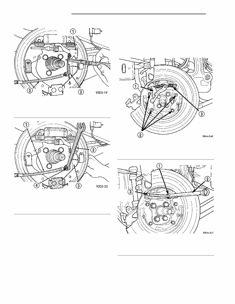
(16) T o remove the parking brake cable from the disc brake adapter on vehicles equipped with rear disc brakes: (a) Remove the parking brake actuating lever from the parking brake cable (Fig. 11). (b) Remove the parking brake cable from the rear disc brake adapter . The parking brake cable can be removed from the disc brake adapter using a 1 /2 inch offset box wrench to compress the locking fingers on the parking brake cable retainer (Fig. 12). Fig. 9 Actuating Spring 1 - BRAKE SHOE ADJUSTMENT LEVER 2 - ADJUSTMENT LEVER ACTUATING SPRING 3 - PARK BRAKE CABLE Fig. 10 Parking Brake Cable Removal 1 - PARK BRAKE CABLE 2 - 1/2 WRENCH 3 - REAR BRAKE SUPPORT PLATE 4 - PARK BRAKE CABLE RETAINER Fig. 11 Parking Brake Actuator Lever 1 - SHOE ACTUATOR LEVER 2 - SHIELD MOUNTING SCREWS 3 - REAR PARKING BRAKE CABLE Fig. 12 Parking Brake Cable Removal 1 - CABLE RETAINER 2 - OFFSET BOX WRENCH 3 - PARKING BRAKE CABLE 2 - 32 REARSUSPENSION PT AXLE - FRONT WHEEL DRIVE REAR (Continued)
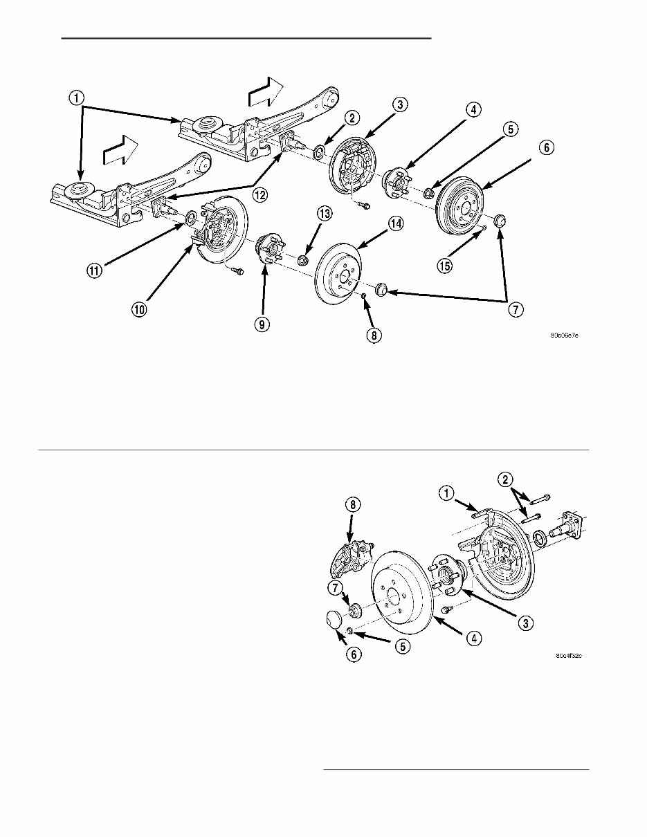
(4) On vehicles equipped with rear disc brakes: (a) Remove the boltssecuring the disc brake flex hose to the axle trailing arm. (b) Remove the disc brake caliper guide pin bolts, then the caliper from the disc brake adapter (Fig. 27). (c) Hang the caliper out of the way using a wire hanger or bungee cord. (d) Remove the brake rotor from the rear hub and bearing. (5) Remove the dust cap from the rear hub and bearing (Fig. 26). (6) Remove the hub and bearing retaining nut from the spindle, then remove the hub and bearing (Fig. 26). (7) Remove the two bolts on each axle trailing arm securing the parking brake cable and routing brack- ets to the axle trailing arm (Fig. 28). (8) On vehicles equipped with antilock brakes, remove the bolt securing the wheel speed sensor to the disc brake adapter (Fig. 29). Remove the sensor from the adapter . (9) Remove the four boltssecuring the brake shoe support plate (drum brakes)or disc brake adapter , and spindle to the axle (Fig. 26). Fig. 26 Rear Brake Mounting To Axle 1 - AXLE 2 - SEAL 3 - DRUM BRAKE WITH SUPPORT PLATE 4 - HUB AND BEARING 5 - HUB NUT 6 - BRAKE DRUM 7 - DUST CAP 8 - RETAINER CLIP 9 - HUB AND BEARING 10 - DISC BRAKE ADAPTER 11 - SEAL 12 - SPINDLE 13 - HUB NUT 14 - BRAKE ROTOR 15 - RETAINER CLIP Fig. 27 Rear Disc Brakes 1 - DISC BRAKE ADAPTER 2 - GUIDE PIN BOLTS 3 - HUB AND BEARING 4 - BRAKE ROTOR 5 - RETAINER CLIP 6 - DUST CAP 7 - NUT 8 - DISC BRAKE CALIPER PT REARSUSPENSION 2 - 43 SPINDLE (Continued)
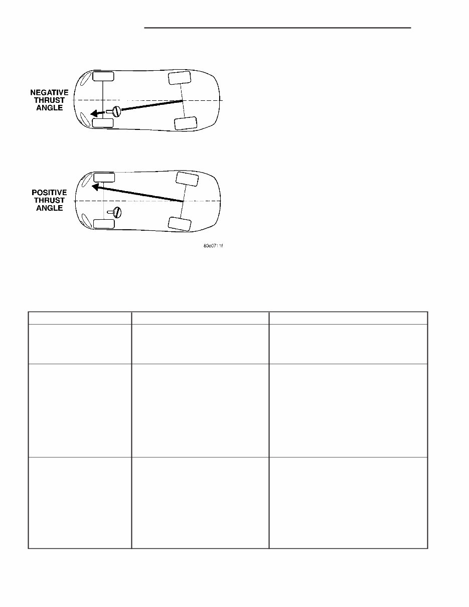
DIAGNOSIS AND TESTING - SUSPENSION ANDSTEERING CONDITION POSSIBLE CAUSES POTENTIAL CORRECTIONS Front End Whine On Turns 1. Defective Wheel Bearing 1. Replace Wheel Bearing 2. Incorrect Wheel Alignment 2. Check And Reset Wheel Alignment 3. Worn Tires 3. Replace Tires Front End Growl Or Grinding On Turns 1. Defective Wheel Bearing 1. Replace Wheel Bearing 2. Engine Mount Grounding Against Frame Or Body Of Vehicle. 2. Check For Motor Mount Hitting Frame Rail And Reposition Engine As Required 3. Worn Or Broken C/V Joint 3. Replace C/V Joint 4. Loose Wheel Lug Nuts 4. Verify Wheel Lug Nut Torque 5. Incorrect Wheel Alignment 5. Check And Reset Wheel Alignment 6. Worn Tires 6. Replace Tires Front End Clunk Or Snap On Turns 1. Loose Wheel Lug Nuts 1. Verify Wheel Lug Nut Torque 2. Worn Or Broken C/V Joint 2. Replace C/V Joint 3. Worn Or Loose Tie Rod Or Ball Joint 3. Tighten Or Replace Tie Rod End Or Ball Joint 4. Worn Control Arm Bushing 4. Replace Control Arm Bushing 5. Loose Sway Bar Or Upper Strut Attachment 5. Tighten Sway Bar Or Upper Strut Attachment To Specified Torque Fig. 6 Thrust Angle 2 - 56 WHEEL ALIGNMENT PT WHEEL ALIGNMENT (Continued)
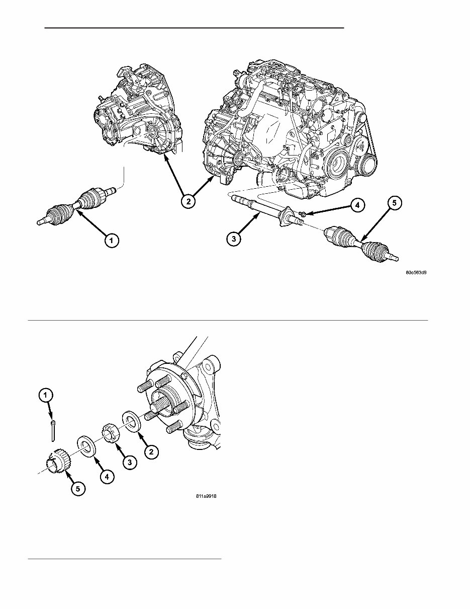
OPERATION Halfshaft assemblies are designed to transmit power from the transaxle to the front wheels, while allowing for powertrain and suspension flex. DIAGNOSIS AND TESTING - HALFSHAFT DIAGNOSIS VEHICLEINSPECTION (1) Check for grease in the vicinity of the inboard tripod joint and outboard C/V joint; this is a sign of inner or outer joint seal boot or seal boot clampdam- age. NOISEAND/OR VIBRATION IN TURNS Aclicking noise and/or a vibration in turns could be caused by one of the following conditions: (1) Loose hub nut. Using a click-style torque wrench, torque hub nutto 244 N·m (180 ft. lbs.). (2) Damaged outer C/V or inner tripod joint seal boot or seal boot clamps, which is evident by the presence of grease slung outward from the joint. This will result in the loss and/or contamination of the joint grease, resulting in inadequate lubrication of the joint. Fig. 2 Halfshaft and Intermediate Shaft (2.2L TD Shown—2.4L Turbo Similar) 1 - HALFSHAFT (LH) 2 - TRANSAXLE 3 - INTERMEDIATE SHAFT 4 - BOLT (3) 5 - HALFSHAFT (RH) Fig. 3 Halfshaft Retaining Hardware 1 - COTTER KEY 2 - WASHER 3 - HUB NUT 4 - SPRING WASHER 5 - NUT LOCK PT HALF SHAFT 3 - 3 HALF SHAFT (Continued)
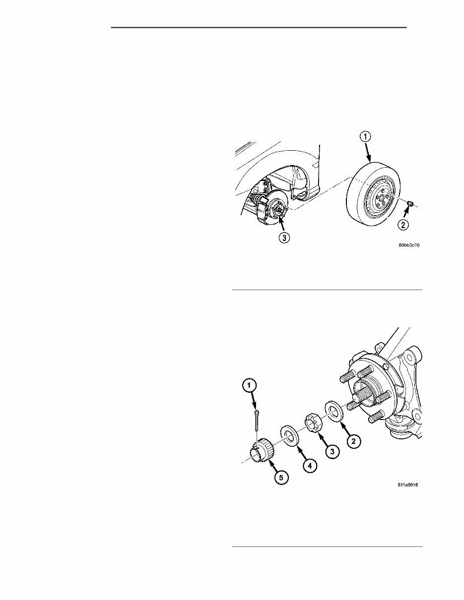
(3) Noise may also be caused by another compo- nent of the vehicle coming in contact with the half- shafts. CLUNKING NOISE DURING ACCELERATION This noise may be a result of one of the following conditions: (1) A torn seal boot on the inner or outer joint of the halfshaft assembly , which is evident by the pres- ence of grease slung outward from the joint. This will result in the loss and/or contamination of the joint grease, resulting in inadequate lubrication of the joint. (2)A loose or missing clamp on the inner or outer joint of the halfshaft assembly . This may be accom- panied by the visible loss of grease. (3)A damaged or wornhalfshaft C/V joint. Isolate the noise toone side of the vehicle. Replace only the affected side. Replacing bothhalfshafts is not neces- sary . SHUDDER OR VIBRATION DURING ACCELERATION (1)A worn or damaged halfshaft inner tripod joint. Isolate the condition to one side of the vehicle. Replace only the affected side. Replacing bothhalf- shafts is not necessary . (2)A sticking tripod joint spider assembly (inner tripod joint only). Isolate the condition toone side of the vehicle. Replace only the affected side. Replacing bothhalfshafts is not necessary . (3) Improper wheel balance. VIBRATION AT HIGHWAY SPEEDS (1) Foreign material (mud, etc.) packed on the backside of the wheel(s). (2) Out of balance fronttires or wheels. (3) Improper tire and/or wheel runout. REMOVAL REMOVAL—EXCEPT DIESEL AND TURBO MODELS CAUTION: Boot sealing is vital to retain special lubricants and to prevent foreign contaminants from entering the C/V joint. Mishandling, such as allowing the assemblies to dangle unsupported, or pulling or pushing the ends can cut boots or dam- age C/V joints. During removal and installation pro- cedures, always support both ends of the halfshaft to prevent damage. CAUTION: The halfshaft, when installed, acts as a bolt and secures the front hub/bearing assembly. If vehicle is to be supported or moved on its wheels with a halfshaft removed, install a PROPER–SIZED BOLT AND NUT through front hub. Tighten bolt and nut to 244 N·m (180 ft. lbs.). This will ensure that the hub bearing cannot loosen. (1) Disconnect battery negative cable. (2) Place transaxle in gatedpark. (3) Raise vehicle onhoist. (4) Remove wheel and tire assembly (Fig.4). (5) Remove the cotter pin, nut lock, and spring washer , and hub nut from theend of the outer C/V joint stub axle (Fig.5). Fig. 4 Wheel and Tire Removal 1 - WHEEL/TIRE ASSY. 2 - LUG NUT (5) 3 - HUB Fig. 5 Halfshaft Retaining Hardware 1 - COTTER KEY 2 - WASHER 3 - HUB NUT 4 - SPRING WASHER 5 - NUT LOCK 3 - 4 HALF SHAFT PT HALF SHAFT (Continued)
Discover the 2005 Chrysler PT Cruiser (Sedan/Convertible) Service & Repair Manual. This manual offers comprehensive guidance for maintaining and repairing your vehicle, featuring detailed step-by-step instructions and illustrations covering engine maintenance, electrical system troubleshooting, brake system repairs, and more.
Whether you're a professional mechanic or a DIY enthusiast, this manual is a valuable resource designed for the 2005 Chrysler PT Cruiser Sedan and Convertible models, helping you save time and money on repairs.
Key features of this manual include:
Comprehensive coverage of all systems and components
Detailed explanations of diagnostic procedures
Step-by-step instructions for maintenance and repairs
Clear illustrations and diagrams for better understanding
Tips and tricks from experienced technicians
Troubleshooting charts for quick problem identification
Wiring diagrams for easy electrical system repairs
And more
Get the 2005 Chrysler PT Cruiser (Sedan/Convertible) Service & Repair Manual today to keep your vehicle in top condition. With this manual, you'll have the confidence and knowledge to handle any repair or maintenance task.
Recently Viewed
5,521,897Happy Clients
2,594,462eManuals
1,120,453Trusted Sellers
15Years in Business
Price:
Actual Price:
2005 Chrysler PT Cruiser (Sedan/Convertible) Service & Repair Manual

 Service & Repair Manual")