Chrysler Cirrus Dodge Stratus Plymouth Breeze Automotive Repair Manual by Marc M Scribner and John H Haynes Member of the Guild of Motoring Writers Models covered: Chrysler Cirrus, Dodge Stratus and Plymouth Breeze 1995 through 2000 Haynes' (10C 1 - 25015) IMTS H Accm MEMBER ASSOCIATION ABODE FGHIJ KLMN Haynes Publishing Group Sparkford Nr Yeovil Somerset BA22 7JJ England Haynes North America, Inc 861 Lawrence Drive Newbury Park California 91320 USA
About this manual Its purpose must pass on to you to cover its labor and The purpose of this manual is to help overhead costs. An added benefit is the you get the best value from your vehicle. It sense of satisfaction and accomplishment can do so in several ways. It can help you that you feel after doing the job yourself. decide what work must be done, even if you Using the manual choose to have it done by a dealer service department or a repair shop; it provides infor- The manual is divided into Chapters. Each Chapter is divided into numbered Sec- tions, which are headed in bold type between horizontal lines. Each Section consists of consecutively numbered paragraphs. At the beginning of each numbered Sec- tion you will be referred to any illustrations which apply to the procedures in that Sec- tion. The reference numbers used in illustra- tion captions pinpoint the pertinent Section and the Step within that Section. That is, illustration 3.2 means the illustration refers to Section 3 and Step (or paragraph) 2 within NOTE A Note provides information necessary to properly complete a procedure or information which will make the procedure easier to understand. CAUTION A Caution provides a special procedure or special steps which must be taken while completing the procedure where the Caution is found. Not heeding a Caution can result in damage to the assembly being worked on. WARNING A Warning provides a special procedure or special steps which must be taken while completing the procedure where the Warning is found. Not heeding a Warning can result in personal injury. Introduction to the Chrysler Cirrus, Dodge Stratus and Plymouth Breeze The Chrysler Cirrus, Dodge Stratus and injection system. lateral links. Plymouth Breeze models are four-door sedan The engine transmits power to the front The standard power rack and pinion type body styles. They feature transversely wheels through either a five-speed manual steering unit is mounted behind the engine mounted engines which were offered in three transaxle or a four-speed automatic transaxle on the front suspension crossmember. An displacements; a 2.0 liter in-line four-cylinder via independent driveaxles. electronically controlled variable-assist engine with a Single Overhead-Camshaft All models feature an all steel unibody speed-proportional power steering was avail- (SOHC), a 2.4 liter in-line four-cylinder engine design and independent front and rear sus- able as an option, which provided maximum with a Dual Overhead-Camshaft (DOHC) and pension. The front suspension incorporates a power steering at low vehicle speeds. the 60-degree V6 six-cylinder engine with shock absorber/coil spring assembly with All models are equipped with power Single Overhead-Camshafts (SONG) (one upper and lower control arms, while the rear assisted front disc and rear drum brakes with over each cylinder head). suspension utilizes a shock absorber/coil an Anti-lock Brake System (ABS) available as All models are equipped with an elec- spring assembly and upper control arm an option. tronically controlled multi-port electronic fuel in combination with a trailing arm and mation and procedures for routine mainte- nance and servicing; and it offers diagnostic and repair procedures to follow when trouble occurs. We hope you use the manual to tackle the work yourself. For many simpler jobs, doing it yourself may be quicker than arrang- ing an appointment to get the vehicle into a shop and making the trips to leave it and pick it up. More importantly, a lot of money can be saved by avoiding the expense the shop that Section. Procedures, once described in the text, are not normally repeated. When it's neces- sary to refer to another Chapter, the refer- ence will be given as Chapter and Section number. Cross references given without use of the word "Chapter" apply to Sections and/or paragraphs in the same Chapter. For example, "see Section 8" means in the same Chapter. References to the left or right side of the vehicle assume you are sitting in the driver's seat, facing forward. Even though we have prepared this manual with extreme care, neither the pub- li sher nor the author can accept responsibility for any errors in, or omissions from, the infor- mation given.
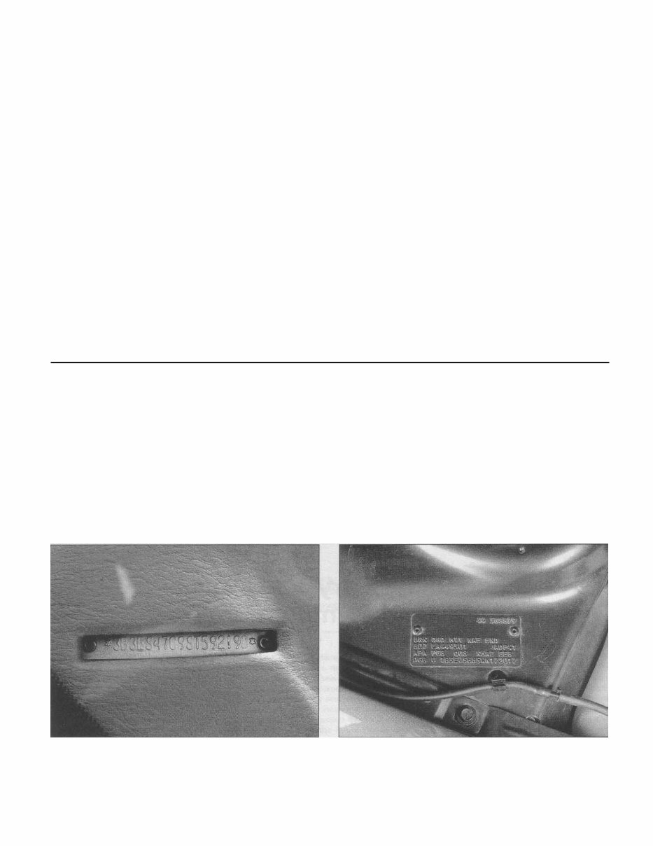
0-6 Vehicle identification numbers Modifications are a continuing and cate of Title and Registration. It contains On the models covered by this manual the unpublicized process in vehicle manufactur- information such as where and when the engine codes are: ing. Since spare parts manuals and lists are vehicle was manufactured, the model year C............................ 2.0L 4-cyl SOHC compiled on a numerical basis, the individual and the body style. H ............................ 2.5L V6 SOHC vehicle numbers are essential to correctly X............................ 2.4L 4-cyl DOHC identify the component required. VIN engine and model year On the models covered by this manual the Vehicle Identification Number codes model year codes are: (VIN) Two particularly important pieces of very important identification num- information found in the VIN are the engine This is located on a plate attached to the code and the model year code. Counting ber dashboard insi d e the windshield on the from the left, the engine code letter designa- tion is the 8th digit and the model year code driver's side of the vehicle (see illustration). designation is the 10th digit. The VIN also appears on the Vehicle Certifi - S........................... 1995 T........................... 1996 V........................... 1997 W.......................... 1998 X........................... 1999 Y........................... 2000 The Vehicle Identification Number (VIN) is stamped into a metal plate fastened to the dashboard on the driver's side - it's visible through the windshield The Body Code Plate is mounted to the right hand shock tower in the engine compartment
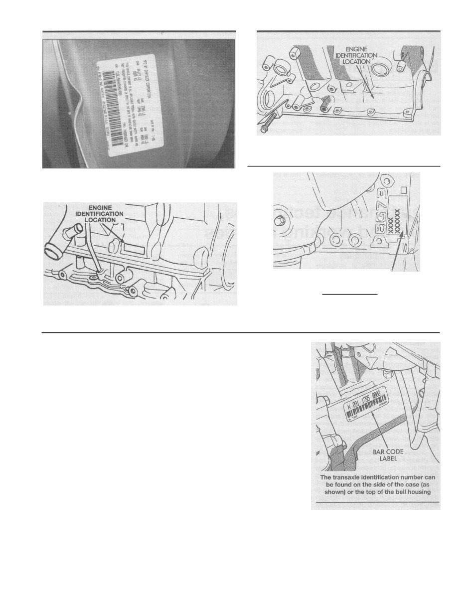
Vehicle identification numbers 0-7 On 2.0L four-cylinder engines, the engine identification number is stamped on the left rear of the engine block (behind the starter motor) The Vehicle Safety Certification label is affixed to the rear edge of the driver's door 2.4L four-cylinder engine identification number locations On V6 engines, the engine identification number is located on the rear of the engine block just below the cylinder head • OIL FILTER ENGINE SERIAL NUMBER AND VIN NUMBER Body Code Plate The Body Code Plate is a stamped metal plate attached to the driver's side shock tower in the engine compartment (see illus- tration). It contains more specific information about the manufacturing of the vehicle such as the paint code, trim code and vehicle order number, as well as the VIN. Vehicle Safety Certification label The Vehicle Safety Certification label is attached to the driver's side door end (see illustration). The label contains the name of the manufacturer, the month and year of pro- duction, the Gross Vehicle Weight Rating (GVWR), the Gross Axle Weight Rating (GAWR) and the certification statement. Engine identification numbers The 2.0L and 2.4L four-cylinder engine identification numbers can be found stamped on a machined pad on the left rear of the engine block. 2.5L V6 engine identification is located on the rear of the engine block just below the cylinder head (see illustrations). Transaxle identification numbers The transaxle identification information can be found on a bar code label located on the front of the transaxle (see illustration). Vehicle Emissions Control Information (VECI) label The emissions control information label is found under the hood, normally on the radiator support or the bottom side of the hood. This label contains information on the emissions control equipment installed on the vehicle, as well as tune-up specifications (see Chapter 6 for more information).
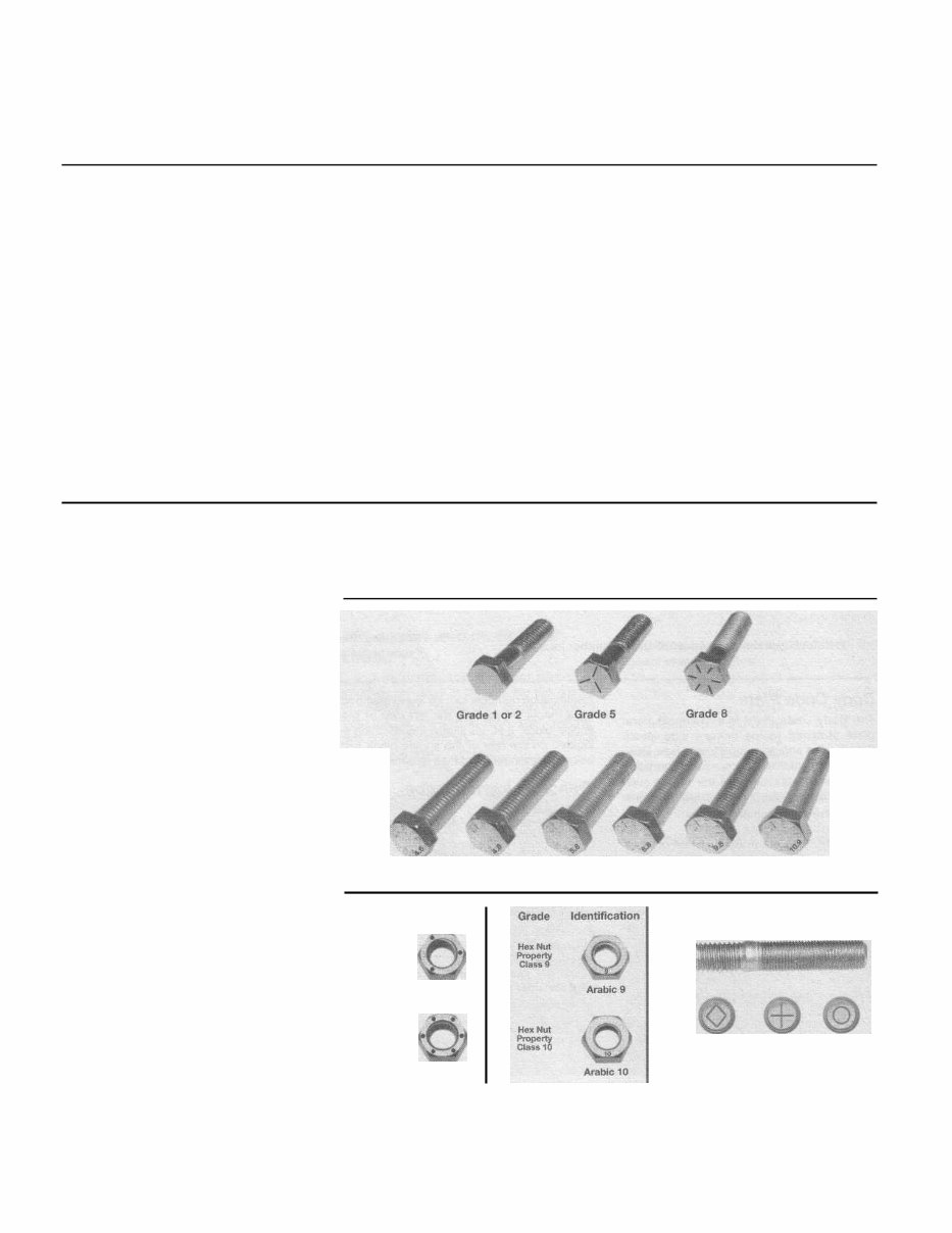
0-8 Buying parts Replacement parts are available from many sources, which generally fall into one of two categories - authorized dealer parts departments and independent retail auto parts stores. Our advice concerning these parts is as follows: Retail auto parts stores: Good auto parts stores will stock frequently needed components which wear out relatively fast, such as clutch components, exhaust sys- tems, brake parts, tune-up parts, etc. These stores often supply new or reconditioned parts on an exchange basis, which can save a considerable amount of money. Discount auto parts stores are often very good places to buy materials and parts needed for general vehicle maintenance such as oil, grease, fil- ters, spark plugs, belts, touch-up paint, bulbs, etc. They also usually sell tools and general accessories, have convenient hours, charge lower prices and can often be found not far from home. Authorized dealer parts department: This is the best source for parts which are unique to the vehicle and not generally avail- able elsewhere (such as major engine parts, transmission parts, trim pieces, etc.). Warranty information: If the vehicle is still covered under warranty, be sure that any replacement parts purchased - regardless of the source - do not invalidate the warranty! To be sure of obtaining the correct parts, have engine and chassis numbers available and, if possible, take the old parts along for positive identification. Maintenance techniques, tools and working facilities Maintenance techniques There are a number of techniques involved in maintenance and repair that will be referred to throughout this manual. Appli- cation of these techniques will enable the home mechanic to be more efficient, better organized and capable of performing the var- ious tasks properly, which will ensure that the repair job is thorough and complete. Fasteners Fasteners are nuts, bolts, studs and screws used to hold two or more parts together. There are a few things to keep in mind when working with fasteners. Almost all of them use a locking device of some type, either a lockwasher, locknut, locking tab or thread adhesive. All threaded fasteners should be clean and straight, with undam- aged threads and undamaged corners on the hex head where the wrench fits. Develop the habit of replacing all damaged nuts and bolts with new ones. Special locknuts with nylon or fiber inserts can only be used once. If they are removed, they lose their locking ability and must be replaced with new ones. Rusted nuts and bolts should be treated with a penetrating fluid to ease removal and prevent breakage. Some mechanics use tur- pentine in a spout-type oil can, which works quite well. After applying the rust penetrant, let it work for a few minutes before trying to loosen the nut or bolt. Badly rusted fasteners may have to be chiseled or sawed off or removed with a special nut breaker, available at tool stores. If a bolt or stud breaks off in an assem- bly, it can be drilled and removed with a spe- cial tool commonly available for this purpose. Most automotive machine shops can perform this task, as well as other repair procedures, such as the repair of threaded holes that have been stripped out. Flat washers and lockwashers, when removed from an assembly, should always be replaced exactly as removed. Replace any damaged washers with new ones. Never use a lockwasher on any soft metal surface (such as aluminum), thin sheet metal or plastic. Metric stud strength markings Bolt strength marking (standard/SAE/USS; bottom - metric) Grade 8 Grade 1 or 2 Grade 5 Standard hex nut strength markings Metric hex nut strength markings Grade Identification 3 Dots 6 Dots Hex Nut Grade 5 Hex Nut Grade 8 Class 10.9 Class 9.8 Class 8.8
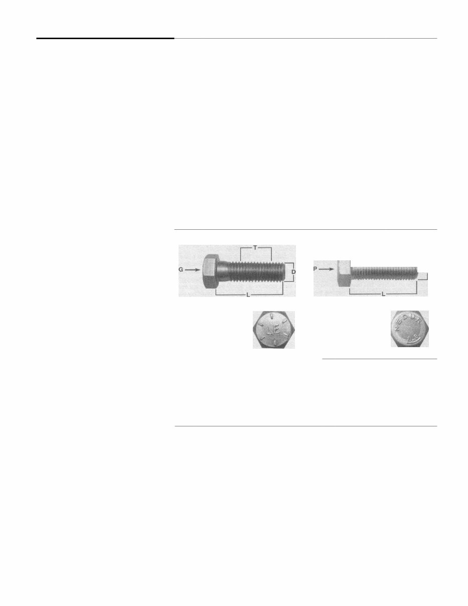
Maintenance techniques, tools and working facilities 0-9 Metric thread sizes Ft-lbs 6to9 Nm 9to12 M-6 ............................................................... M-8 ............................................................... 14to21 19to28 M-10............................................................. 28to40 38to54 M-12............................................................. 50 to 71 68 to 96 M-14............................................................. 80 to 140 109 to 154 Pipe thread sizes 5to8 7to10 1 /8 ................................................................ 1 /4................................................................ 12 to 18 17 to 24 3/8................................................................ 22 to 33 30 to 44 1 /2 ................................................................ 25 to 35 34 to 47 U.S. thread sizes 6to9 9to12 1/4-20 ......................................................... 5/16 - 18 ....................................................... 12to18 17to24 5/16 - 24 ....................................................... 14 to 20 19 to 27 3/8 - 16......................................................... 22 to 32 30 to 43 3/8 - 24 ......................................................... 27 to 38 37 to 51 7/16 - 14 ....................................................... 40 to 55 55 to 74 7/16-20 ....................................................... 40 to 60 55 to 81 1 /2 - 13 ......................................................... 55 to 80 75 to 108 Fastener sizes For a number of reasons, automobile manufacturers are making wider and wider use of metric fasteners. Therefore, it is impor- tant to be able to tell the difference between standard (sometimes called U.S. or SAE) and metric hardware, since they cannot be inter- changed. All bolts, whether standard or metric, are sized according to diameter, thread pitch and length. For example, a standard 1/2 - 13 x 1 bolt is 1/2 inch in diameter, has 13 threads per inch and is 1 inch long. An M12 - 1.75 x 25 metric bolt is 12 mm in diameter, has a thread pitch of 1.75 mm (the distance between threads) and is 25 mm long. The two bolts are nearly identical, and easily confused, but they are not interchangeable. In addition to the differences in diame- ter, thread pitch and length, metric and stan- dard bolts can also be distinguished by examining the bolt heads. To begin with, the distance across the flats on a standard bolt head is measured in inches, while the same dimension on a metric bolt is sized in millime- ters (the same is true for nuts). As a result, a standard wrench should not be used on a metric bolt and a metric wrench should not be used on a standard bolt. Also, most stan- dard bolts have slashes radiating out from the center of the head to denote the grade or strength of the bolt, which is an indication of the amount of torque that can be applied to it. The greater the number of slashes, the greater the strength of the bolt. Grades 0 through 5 are commonly used on automo- biles. Metric bolts have a property class (grade) number, rather than a slash, molded into their heads to indicate bolt strength. In this case, the higher the number, the stronger the bolt. Property class numbers 8.8, 9.8 and 10.9 are commonly used on automobiles. Strength markings can also be used to distinguish standard hex nuts from metric hex nuts. Many standard nuts have dots stamped into one side, while metric nuts are marked with a number. The greater the num- ber of dots, or the higher the number, the greater the strength of the nut. Metric studs are also marked on their ends according to property class (grade). Larger studs are numbered (the same as metric bolts), while smaller studs carry a geo- metric code to denote grade. It should be noted that many fasteners, especially Grades 0 through 2, have no dis- tinguishing marks on them. When such is the case, the only way to determine whether it is standard or metric is to measure the thread pitch or compare it to a known fastener of the same size. Standard fasteners are often referred to as SAE, as opposed to metric. However, it should be noted that SAE technically refers to a non-metric fine thread fastener only. Coarse thread non-metric fasteners are referred to as USS sizes. Since fasteners of the same size (both standard and metric) may have different strength ratings, be sure to reinstall any bolts, studs or nuts removed from your vehicle in their original locations. Also, when replacing a fastener with a new one, make sure that the new one has a strength rating equal to or greater than the original. Tightening sequences and procedures Most threaded fasteners should be tightened to a specific torque value (torque is the twisting force applied to a threaded com- ponent such as a nut or bolt). Overtightening the fastener can weaken it and cause it to break, while undertightening can cause it to eventually come loose. Bolts, screws and studs, depending on the material they are made of and their thread diameters, have specific torque values, many of which are noted in the Specifications at the beginning of each Chapter. Be sure to follow the torque recommendations closely. For fasteners not assigned a specific torque, a general torque value chart is presented here as a guide. These torque values are for dry (unlubricated) fasteners threaded into steel or cast iron (not aluminum). As was previously mentioned, the size and grade of a fastener determine the amount of torque that can safely be applied to it. The figures listed here are approximate for Grade 2 and Grade 3 fasteners. Higher grades can tolerate higher torque values. Fasteners laid out in a pattern, such as cylinder head bolts, oil pan bolts, differential cover bolts, etc., must be loosened or tight- T -I J * f Cfiffko r i, p !`S' o . ,'v, D I W-2 HAYNES I Standard (SAE and USS) bolt Metric bolt dimensions/grade marks dimensions/grade marks P Property class (bolt strength) G Grade marks (bolt strength) L Length (in millimeters) L Length (in inches) T Thread pitch (distance between T Thread pitch (number of threads per threads in millimeters) inch) D Diameter D Nominal diameter (in inches)
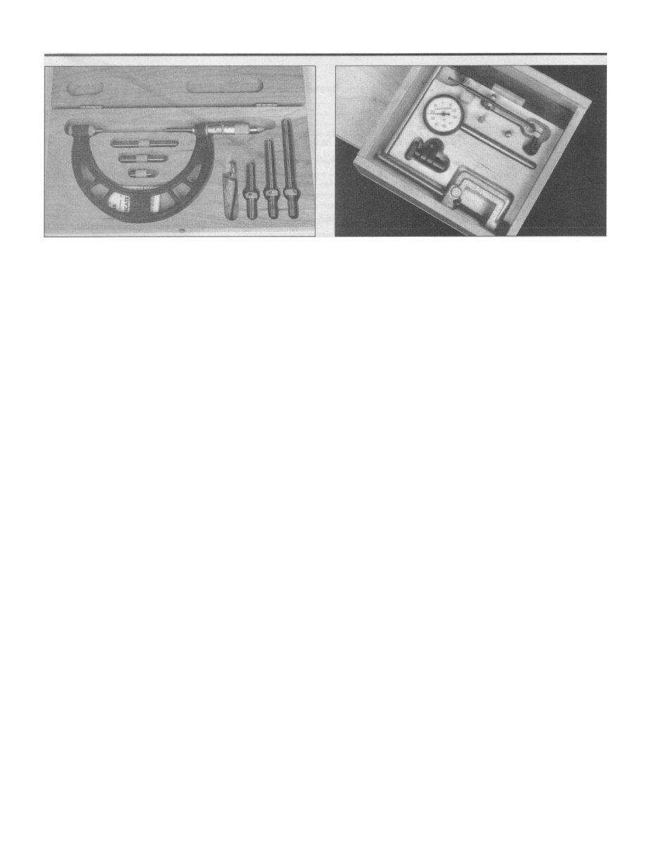
0-10 Maintenance techniques, tools and working facilities Micrometer set ened in sequence to avoid warping the com- ponent. This sequence will normally be shown in the appropriate Chapter. If a spe- cific pattern is not given, the following proce- dures can be used to prevent warping. Initially, the bolts or nuts should be assembled finger-tight only. Next, they should be tightened one full turn each, in a criss-cross or diagonal pattern. After each one has been tightened one full turn, return to the first one and tighten them all one-half turn, following the same pattern. Finally, tighten each of them one-quarter turn at a ti me until each fastener has been tightened to the proper torque. To loosen and remove the fasteners, the procedure would be reversed. Component disassembly Component disassembly should be done with care and purpose to help ensure that the parts go back together properly. Always keep track of the sequence in which parts are removed. Make note of special characteristics or marks on parts that can be installed more than one way, such as a grooved thrust washer on a shaft. It is a good idea to lay the disassembled parts out on a clean surface in the order that they were removed. It may also be helpful to make sketches or take instant photos of compo- nents before removal. When removing fasteners from a com- ponent, keep track of their locations. Some- ti mes threading a bolt back in a part, or putting the washers and nut back on a stud, can prevent mix-ups later. If nuts and bolts cannot be returned to their original locations, they should be kept in a compartmented box or a series of small boxes. A cupcake or muf- fin tin is ideal for this purpose, since each cavity can hold the bolts and nuts from a par- ticular area (i.e. oil pan bolts, valve cover bolts, engine mount bolts, etc.). A pan of this type is especially helpful when working on assemblies with very small parts, such as the carburetor, alternator, valve train or interior dash and trim pieces. The cavities can be marked with paint or tape to identify the con- tents. Whenever wiring looms, harnesses or connectors are separated, it is a good idea to identify the two halves with numbered pieces of masking tape so they can be easily recon- nected. Gasket sealing surfaces Throughout any vehicle, gaskets are used to seal the mating surfaces between two parts and keep lubricants, fluids, vacuum or pressure contained in an assembly. Many times these gaskets are coated with a liquid or paste-type gasket sealing compound before assembly. Age, heat and pressure can sometimes cause the two parts to stick together so tightly that they are very difficult to separate. Often, the assembly can be loosened by striking it with a soft-face hammer near the mating surfaces. A regular hammer can be used if a block of wood is placed between the hammer and the part. Do not hammer on cast parts or parts that could be easily damaged. With any particularly stubborn part, always recheck to make sure that every fastener has been removed. Avoid using a screwdriver or bar to pry apart an assembly, as they can easily mar the gasket sealing surfaces of the parts, which must remain smooth. If prying is absolutely necessary, use an old broom handle, but keep in mind that extra clean up will be nec- essary if the wood splinters. After the parts are separated, the old gasket must be carefully scraped off and the gasket surfaces cleaned. Stubborn gasket material can be soaked with rust penetrant or treated with a special chemical to soften it so it can be easily scraped off. A scraper can be fashioned from a piece of copper tubing by flattening and sharpening one end. Copper is recommended because it is usually softer than the surfaces to be scraped, which reduces the chance of gouging the part. Some gaskets can be removed with a wire brush, but regardless of the method used, the mating surfaces must be left clean and smooth. If for some reason the gasket sur- face is gouged, then a gasket sealer thick enough to fill scratches will have to be used during reassembly of the components. For most applications, a non-drying (or semi-dry- ing) gasket sealer should be used. Dial indicator set Hose removal tips Warning: If the vehicle is equipped with air conditioning, do not disconnect any of the A/C hoses without first having the system depressurized by a dealer service department or a service station. Hose removal precautions closely paral- lel gasket removal precautions. Avoid scratching or gouging the surface that the hose mates against or the connection may leak. This is especially true for radiator hoses. Because of various chemical reactions, the rubber in hoses can bond itself to the metal spigot that the hose fits over. To remove a hose, first loosen the hose clamps that secure it to the spigot. Then, with slip-joint pliers, grab the hose at the clamp and rotate it around the spigot. Work it back and forth until it is completely free, then pull it off. Sili- cone or other lubricants will ease removal if they can be applied between the hose and the outside of the spigot. Apply the same lubricant to the inside of the hose and the outside of the spigot to simplify installation. As a last resort (and if the hose is to be replaced with a new one anyway), the rubber can be slit with a knife and the hose peeled from the spigot. If this must be done, be careful that the metal connection is not dam- aged. If a hose clamp is broken or damaged, do not reuse it. Wire-type clamps usually weaken with age, so it is a good idea to replace them with screw-type clamps when- ever a hose is removed. Tools A selection of good tools is a basic requirement for anyone who plans to main- tain and repair his or her own vehicle. For the owner who has few tools, the initial invest- ment might seem high, but when compared to the spiraling costs of professional auto maintenance and repair, it is a wise one. To help the owner decide which tools are needed to perform the tasks detailed in this manual, the following tool lists are offered: Maintenance and minor repair, Repair/overhaul and Special. The newcomer to practical mechanics
Maintenance techniques, tools and working facilities 0-11 Dial caliper Hand-operated vacuum pump Timing light Compression gauge with spark plug hole adapter Damper/steering wheel puller General purpose puller Hydraulic lifter removal tool Valve spring compressor Valve spring compressor Ridge reamer Piston ring groove cleaning tool Ring removal/installation tool
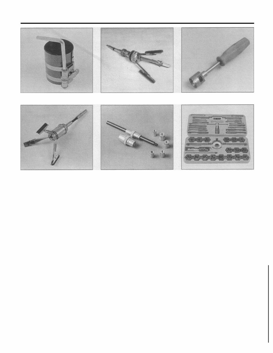
0-12 Maintenance techniques, tools and working facilities Ring compressor Cylinder hone Brake hold-down spring tool Brake cylinder hone should start off with the maintenance and minor repair tool kit, which is adequate for the simpler jobs performed on a vehicle. Then, as confidence and experience grow, the owner can tackle more difficult tasks, buying additional tools as they are needed. Eventually the basic kit will be expanded into the repair and overhaul tool set. Over a period of time, the experienced do-it-yourselfer will assemble a tool set complete enough for most repair and overhaul procedures and will add tools from the special category when it is felt that the expense is justified by the fre- quency of use. Maintenance and minor repair tool kit The tools in this list should be consid- ered the minimum required for performance of routine maintenance, servicing and minor repair work. We recommend the purchase of combination wrenches (box-end and open- end combined in one wrench). While more expensive than open end wrenches, they offer the advantages of both types of wrench. Combination wrench set (1/4-inch to 1 inch or 6 mm to 19 mm) Adjustable wrench, 8 inch Spark plug wrench with rubber insert Spark plug gap adjusting tool Feeler gauge set Brake bleeder wrench Standard screwdriver (5/16-inch x 6 inch) Clutch plate alignment tool Phillips screwdriver (No. 2 x 6 inch) Combination pliers - 6 inch Hacksaw and assortment of blades Tire pressure gauge Grease gun Oil can Fine emery cloth Wire brush Battery post and cable cleaning tool Oil filter wrench Funnel (medium size) Safety goggles Jackstands (2) Drain pan Note: If basic tune-ups are going to be part of routine maintenance, it will be necessary to purchase a good quality stroboscopic timing light and combination tachometer/dwell meter. Although they are included in the list of special tools, it is mentioned here because they are absolutely necessary for tuning most vehicles properly. Repair and overhaul tool set These tools are essential for anyone who plans to perform major repairs and are in addition to those in the maintenance and minor repair tool kit. Included is a compre- hensive set of sockets which, though expen- sive, are invaluable because of their versatil- ity, especially when various extensions and drives are available. We recommend the 1/2- inch drive over the 3/8-inch drive. Although the larger drive is bulky and more expensive, Tap and die set it has the capacity of accepting a very wide range of large sockets. Ideally, however, the mechanic should have a 3/8-inch drive set and a 1/2-inch drive set. Socket set(s) Reversible ratchet Extension - 10 inch Universal joint Torque wrench (same size drive as sockets) Ball peen hammer - 8 ounce Soft-face hammer (plastic/rubber) Standard screwdriver (1/4-inch x 6 inch) Standard screwdriver (stubby - 5/16-inch) Phillips screwdriver (No. 3 x 8 inch) Phillips screwdriver (stubby - No. 2) Pliers - vise grip Pliers - lineman's Pliers - needle nose Pliers - snap-ring (internal and external) Cold chisel - 1/2-inch Scribe Scraper (made from flattened copper tubing) Centerpunch Pin punches (1/16, 1/8, 3/16-inch) Steel rule/straightedge - 12 inch Allen wrench set (1/8 to 3/8-inch or 4mmto10mm) A selection of files Wire brush (large) Jackstands (second set) Jack (scissor or hydraulic type)
The Chrysler Cirrus 1995-2000 Full Service Repair Manual is a comprehensive resource designed for individuals working on or owning a Chrysler Cirrus vehicle. This manual offers detailed instructions and diagrams to assist in the maintenance, repair, and servicing of the vehicle.
It provides step-by-step procedures for a wide range of repairs and maintenance tasks, including engine repairs, electrical system diagnostics, brake system maintenance, and more.
Key features of the Chrysler Cirrus 1995-2000 Full Service Repair Manual include:
Detailed instructions covering all models of Chrysler Cirrus from 1995 to 2000
Complete coverage of engine, transmission, suspension, steering, brakes, electrical system, and more
Clear diagrams and illustrations to aid in understanding and performing repairs
Step-by-step procedures for removing and installing components
Troubleshooting guides to assist in diagnosing and fixing common problems
Maintenance schedules and procedures to keep your Chrysler Cirrus in top condition
Whether you are a professional mechanic or a DIY enthusiast, the Chrysler Cirrus 1995-2000 Full Service Repair Manual is an invaluable resource for anyone working on these vehicles. Obtain your copy today and gain the knowledge and confidence to tackle any repair or maintenance task.