1971-1995 Chevrolet Van G10 / G20 / G30 Service & Repair Manual
What's Included?
Lifetime Access
Fast Download Speeds
Online & Offline Access
Access PDF Contents & Bookmarks
Full Search Facility
Print one or all pages of your manual
1971-1995 CHEVROLET VAN REPAIR MANUAL
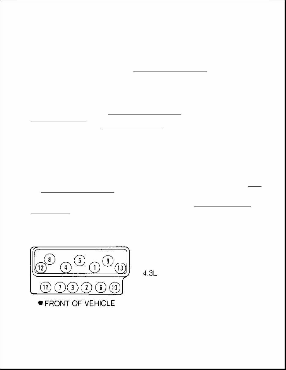
ENGINE OVERHAUL GENERAL MOTORS ENGINES 4.3L V6 ENGINE IDENTIFICATION Engine is identified by eighth character of Vehicle Identification Number (VIN). VIN is stamped on a metal tag on top left end of instrument panel, near windshield. See the ENGINE IDENTIFICATION CODES table. Engine can also be identified by engine identification (ID) number. Number is stamped on front of cylinder block, immediately forward of right cylinder head or on left side of cylinder block, on engine-to-transmission mating flange. ENGINE IDENTIFICATION CODES ADJUSTMENTS VALVE CLEARANCE ADJUSTMENT With Screw-In Rocker Studs Tighten rocker arm nuts to 20 ft. lbs. (27 N.m). With Pressed-In Rocker Studs 1. Rotate engine until No. 1 piston is on TDC of compression stroke. Loosen rocker arm adjusting nut until lash is present. 2. Tighten adjusting nut until lash is removed. Tighten adjusting nut one full turn. Adjust remaining valves (for piston at TDC) as listed in the VALVE CLEARANCE ADJUSTMENT table. 3. Rotate crankshaft 360 degrees to bring No. 4 piston to TDC of compression stroke. Adjust remaining valves. See the VALVE CLEARANCE ADJUSTMENT table. VALVE CLEARANCE ADJUSTMENT (1) NOTE: For engine repair procedures not covered in this article, see ENGINE OVERHAUL PROCEDURES - GENERAL INFORMATION article in the GENERAL INFORMATION section. Application Engine Code VIN Code 4.3L V6 TBI LB4 Z NOTE: Although valve clearance adjustment is not usually required (because the engine uses hydraulic valve lifters), perform the following procedures after servicing valve train. Piston At TDC Intake Exhaust
REMOVAL & INSTALLATION GENERAL PRECAUTION FUEL PRESSURE RELEASE Disconnect battery terminals. Loosen fuel tank cap to relieve tank pressure. Internal constant bleed feature in injection unit relieves fuel system pressure when ignition switch is turned off. No further pressure relief is required. ENGINE R & I Removal & Installation (Commercial Van) 1. Release fuel system pressure. See FUEL PRESSURE RELEASE . Disconnect battery. Drain cooling system. Remove engine cover and floor panel sections. 2. Remove air cleaner, duct and exhaust heat stove pipe. Remove distributor cap and position aside. Disconnect all engine harness electrical connectors and position aside. Disconnect fuel lines from injection unit. Remove fuel line clamps from transmission and position fuel lines aside. 3. Disconnect ground strap from rear end of left cylinder head. Disconnect all transmission harness electrical connectors and position harness aside. Remove transmission shifter (if necessary). Remove upper radiator hose, all accessory drive belts, fan, fan pulley, fan shroud and lower radiator hose. No. 1 No. 1, 2 & 3 No. 1, 5 & 6 No. 4 No. 4, 5 & 6 No. 2, 3 & 4 (1) If equipped with screw-in rocker studs, tighten all rocker arm nuts to 20 ft. lbs. (27 N.m). CAUTION: When battery is disconnected, vehicle computer and memory systems may lose memory data. Driveability problems may exist until computer systems have completed a relearn cycle. See COMPUTER RELEARN PROCEDURES article in GENERAL INFORMATION before disconnecting battery. NOTE: For reassembly reference, label all electrical connectors, vacuum hoses and fuel lines before removal. Also place mating marks on engine hood and other major assemblies before removal. CAUTION: Minimal clearance exists between oil pump pick-up tube and bottom of oil pan. DO NOT place jack under oil pan, crankshaft pulley or any sheet metal when lifting engine. NOTE: On Commercial Van, engine and transmission are removed as an assembly through side door.
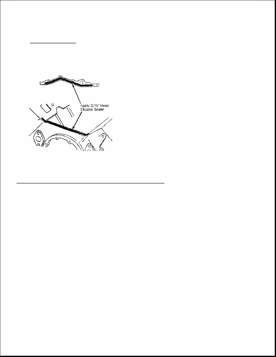
4. Remove engine oil filler tube. Remove clutch adjuster rod, return spring and pivot arm assembly (M/T). Disconnect exhaust pipes from manifolds. Disconnect battery cable from clamp on cylinder block. Disconnect drive shaft from transmission. Remove transmission mount. 5. Disconnect oil cooler lines from oil filter adapter and oil cooler line clamps from engine. Attach engine hoist. Remove engine mount through-bolts. Remove engine and transmission assembly through side door. To install, reverse removal procedure. Fill crankcase and cooling system. Removal & Installation (Van) 1. Release fuel system pressure. See FUEL PRESSURE RELEASE . Disconnect battery. Drain cooling system. Remove engine cover and air cleaner. Remove power steering fluid reservoir. 2. Remove upper fan shroud, fan, fan pulley, radiator and lower fan shroud. Discharge A/C system (if equipped) using approved refrigerant recovery/recycling equipment. Remove A/C condenser. Remove A/C compressor and brace. Remove alternator. Remove cruise control servo (if equipped). 3. Disconnect fuel lines, electrical connectors, vacuum hoses, coolant hoses and control cables as necessary. Remove injection unit. Remove distributor cap with wires attached. Remove diverter valve assembly and pipe. 4. Remove ignition coil and manifold absolute pressure sensor. Remove upper half of engine oil dipstick tube. Remove engine oil filler tube. Remove headlight bezels, grille and upper radiator support (sheet metal cross panel support). 5. Raise and support vehicle. Drain crankcase. Disconnect exhaust pipes from manifolds. Remove strut rods. Remove flywheel cover. Disconnect oil cooler lines from engine. Remove starter, torque converter bolts (A/T) and engine mount through-bolts. 6. Lower vehicle. Attach engine hoist. Remove bellhousing bolts. Support transmission. Remove engine. To install, reverse removal procedure. Fill crankcase and cooling system. Evacuate and charge A/C system. INTAKE MANIFOLD Removal 1. Release fuel system pressure. See FUEL PRESSURE RELEASE . Disconnect battery. Drain cooling system. Remove air cleaner. 2. Disconnect fuel lines, electrical connectors, vacuum hoses, coolant hoses and control cables as necessary. Remove alternator bracket, A/C compressor (with hoses attached), injection unit and cruise control servo as necessary. 3. Remove distributor cap. Mark distributor rotor in relation to distributor housing. Mark base of distributor housing in relation to intake manifold. Remove distributor. Remove intake manifold bolts, intake manifold and gaskets. Installation 1. Install gaskets on cylinder heads. Apply a 3/16" bead of RTV silicone sealant to front and rear intake manifold-to-cylinder block mounting surfaces. See Fig. 1 . Extend bead 1/2" beyond cylinder block-to- cylinder head junction. 2. Install intake manifold and bolts. Tighten bolts in sequence to specification. See Fig. 2 . See TORQUE
SPECIFICATIONS . To complete installation, reverse removal procedure. Fill cooling system. Fig. 1: Applying RTV Sealant Before Installing Intake Manifold Courtesy of GENERAL MOTORS CORP.
Fig. 2: Intake Manifold Bolt Tightening Sequence Courtesy of GENERAL MOTORS CORP. EXHAUST MANIFOLD Removal 1. Remove heat stove tube. Remove all attached brackets and heat shields. If necessary, remove dip stick tube. Disconnect oxygen sensor electrical connector.
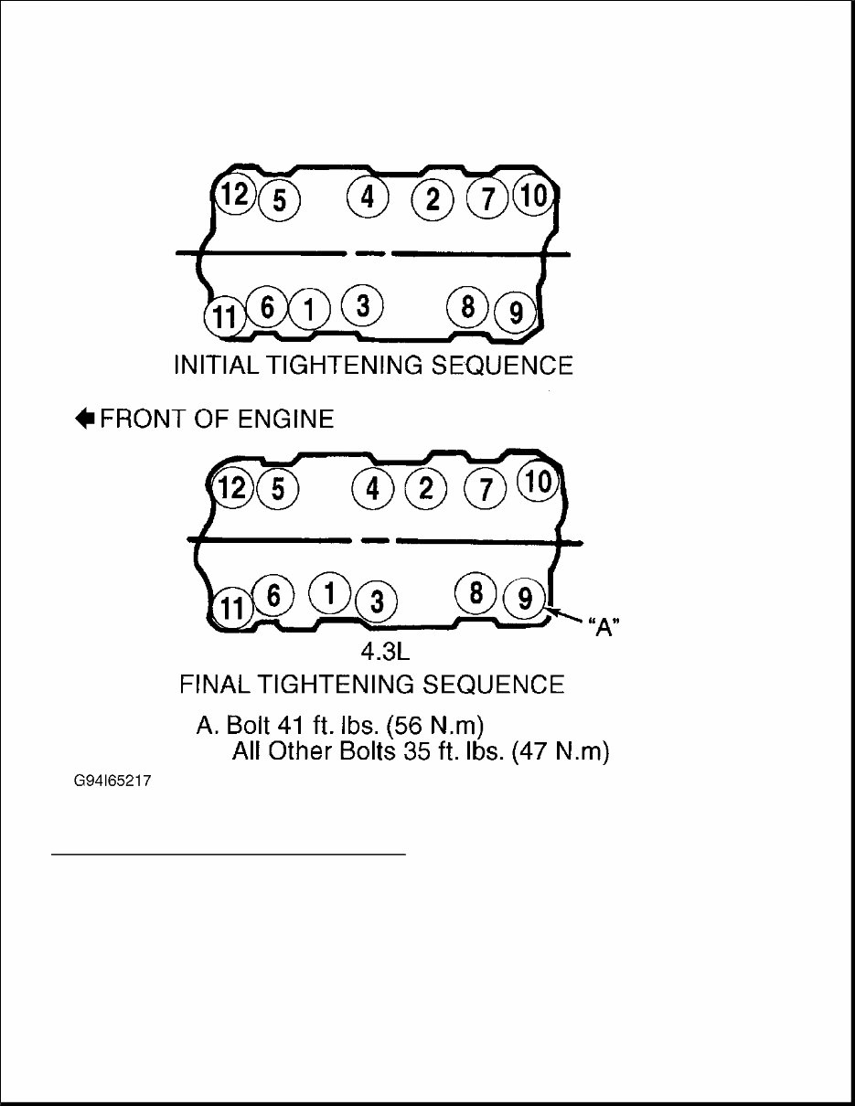
2. Disconnect exhaust pipe from manifold. Remove exhaust manifold bolts and exhaust manifold. Installation Install manifold. Tighten bolts to specification. See TORQUE SPECIFICATIONS . Bend lock tabs (if equipped). To complete installation, reverse removal procedure. CYLINDER HEAD Removal 1. Release fuel system pressure. See FUEL PRESSURE RELEASE . Remove intake manifold. See INTAKE MANIFOLD . 2. Remove exhaust manifold. See EXHAUST MANIFOLD . Remove valve covers. Loosen rocker arm nuts. Rotate rocker arms aside. Remove push rods and mark for reassembly to original locations. Remove cylinder head bolts. Remove cylinder head. Installation 1. Clean gasket surfaces, bolt threads and bolt holes. If using steel head gasket, thinly coat both sides of gasket with sealant. DO NOT apply sealant to composition (steel/asbestos) head gaskets. Position head gasket on cylinder block. Ensure all holes align. Coat head bolt threads with GM Sealant (1052080). 2. Install cylinder head with bolts finger-tight. Tighten head bolts in sequence to specification. See Fig. 3 . See TORQUE SPECIFICATIONS . Lubricate valve tip, rocker arm pivot and push rod socket with Molykote. 3. To complete installation, reverse removal procedure. Adjust valves. See VALVE CLEARANCE ADJUSTMENT under ADJUSTMENTS.
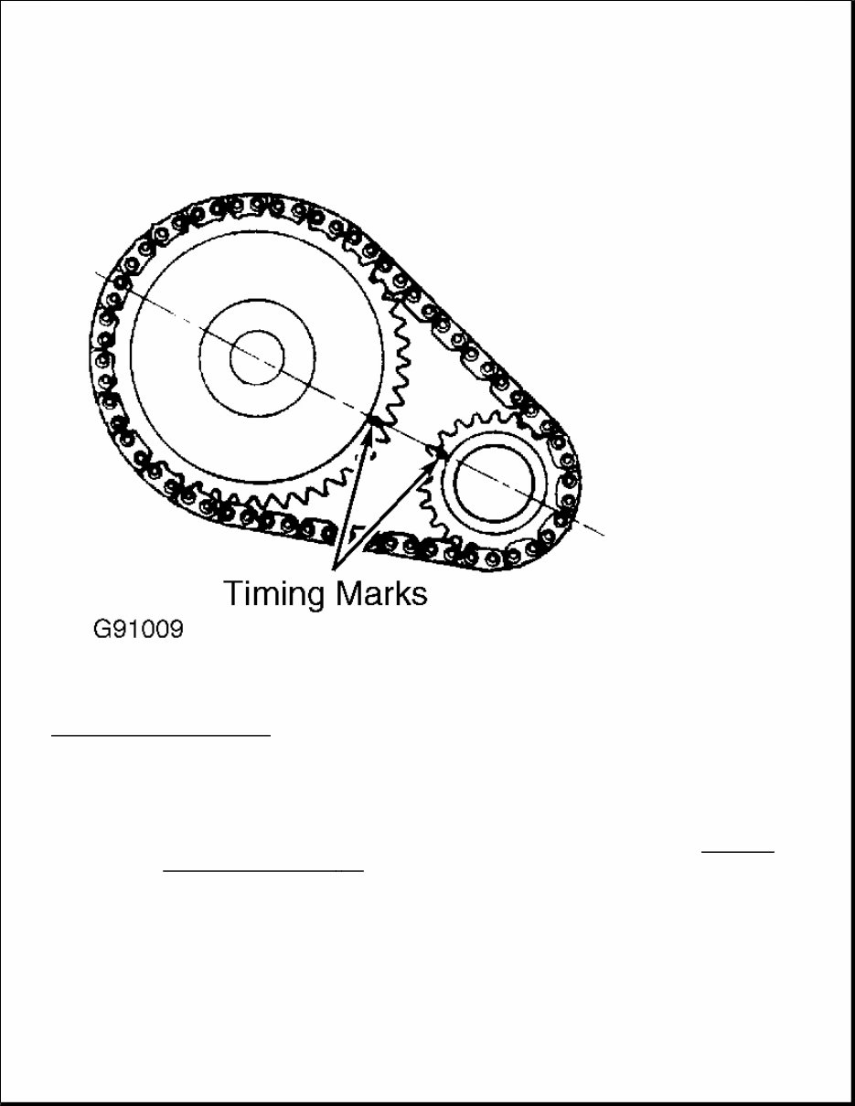
Fig. 3: Cylinder Head Bolt Tightening Sequence Courtesy of GENERAL MOTORS CORP. FRONT COVER OIL SEAL Removal Remove accessory drive belt(s) and pulley. Remove crankshaft damper bolt. Using Damper Puller/Installer (J- 39046), remove crankshaft damper. Pry seal from cover. Installation 1. Coat seal lip with engine oil. Using Seal Installer (J-35468), install NEW seal in front cover with seal lip facing engine. Apply RTV sealant to Woodruff keyway in crankshaft damper. 2. Install crankshaft damper. Install crankshaft damper bolt and tighten to specification. See TORQUE SPECIFICATIONS . To install remaining components, reverse removal procedure. TIMING CHAIN & SPROCKETS Removal 1. Disconnect battery. Drain cooling system. If necessary, remove radiator shroud. Remove accessory drive belts, fan and pulley. Remove crankshaft damper bolt. Using Damper Puller/Installer (J-39046), remove crankshaft damper. 2. Remove all mounting brackets and coolant hoses attached to water pump. Remove water pump. Remove oil pan. See OIL PAN. Remove front cover and gasket. 3. Rotate crankshaft until timing marks on camshaft and crankshaft sprockets are aligned. See Fig. 4 . Remove camshaft sprocket and timing chain. To remove crankshaft sprocket, use Sprocket Puller (J- 5825-A). Installation 1. Install Woodruff key in crankshaft (if removed). Using Crankshaft Sprocket Installer (J-5590), install crankshaft sprocket. Install camshaft sprocket and timing chain, ensuring timing marks on sprockets are aligned. See Fig. 4 . 2. Install and tighten camshaft sprocket bolts to specification. See TORQUE SPECIFICATIONS . Install gasket to front cover with gasket sealant. Install front cover and gasket. 3. Apply RTV sealant to Woodruff keyway in crankshaft damper. Install crankshaft damper. Install crankshaft damper bolt and tighten to specification. See TORQUE SPECIFICATIONS . To complete installation, reverse removal procedure. CAUTION: If engine is equipped with a balance shaft, the timing gear sprocket marks align at TDC of cylinder No. 4.
Fig. 4: Aligning Timing Marks Courtesy of GENERAL MOTORS CORP. ROCKER ARM STUDS (PRESS-FIT) Removal & Installation NOTE: Some engines are equipped with press-fit, others with screw-in. This procedure is for the press-fit type. If engine is equipped with screw in, refer to ROCKER ARM STUDS (SCREW - IN) . CAUTION: Ream rocker arm stud bore before installing oversize rocker arm stud, or cylinder head may be damaged.
1. Rocker arm studs are pressed into cylinder head. Using Stud Remover (J-5802-01), place remover over stud. Install flat washer and nut. Tighten nut to remove stud from cylinder head. 2. If stud is loose in cylinder head, ream stud bore for oversize stud using Reamer (J-5715) for .003" (.08 mm) oversize stud or (J-6036) for .013" (.33 mm) oversize stud. 3. Coat press-fit area of stud with hypoid axle lubricant. Using Stud Driver (J-6880), drive stud into bore until driver bottoms against cylinder head. ROCKER ARM STUDS (SCREW-IN) Removal & Installation Unscrew rocker arm stud from cylinder head. To install, insert NEW rocker arm stud and tighten to 35 ft. lbs. (47 N.m). VALVE LIFTERS Removal 1. Remove intake manifold. See INTAKE MANIFOLD . Remove valve covers. Loosen all rocker arm nuts and rotate rockers aside. 2. Remove push rods, noting location for reassembly reference. Remove lifter retainer. Remove roller lifter guides (if equipped). Remove lifters, noting location for reassembly reference. Installation Coat lifter base or roller (if equipped) and body with High Viscosity Oil/Zinc (12345501). Install lifters in original location. To complete installation, reverse removal procedure. CAMSHAFT Removal 1. Remove radiator. Discharge A/C system (if equipped) using approved refrigerant recovery/recycling equipment and remove A/C condenser (if equipped) and grille. Remove valve lifters. See VALVE LIFTERS . 2. Remove timing chain and camshaft sprocket. See TIMING CHAIN & SPROCKETS . Remove balance shaft gear (if equipped). Remove thrust plate. If necessary, raise engine. Remove camshaft. Installation Coat camshaft lobes and bearing journals with High Viscosity Oil/Zinc (12345501). Install camshaft. To complete installation, reverse removal procedure. NOTE: Some engines are equipped with press-fit, others with screw-in type. This procedure is for the screw-in type. If engine is equipped with press-fit type, see ROCKER ARM STUDS (PRESS - FIT) .
1971-1995 Chevrolet Van G10 / G20 / G30 Service & Repair Manual
Engines covered:
4.3L V6
5.0L V8
5.7L V8
6.5L diesel V8
7.4L V8
This comprehensive truck repair manual is designed to assist both professional mechanics and DIY enthusiasts in troubleshooting and replacing components. It includes step-by-step instructions, clear images, and exploded-view illustrations provided by the manufacturer.
Regular maintenance is essential for the durability of your truck. Over time, certain parts will wear out and require replacement. This manual equips you with the manufacturer's recommended troubleshooting charts and replacement procedures, enabling you to save on repairs, enhance your vehicle's reliability, and minimize visits to the repair shop.
Featuring every troubleshooting and replacement procedure, along with clear images and exploded-view illustrations, this manual eliminates the need to search through numerous pages for specific information. It offers a convenient alternative to traditional bound manuals, allowing easy access, search, screenshot, and bookmark functions.
Moreover, the manual is printable and compatible with various electronic devices, including PC & Mac computers, Android and Apple smartphones & tablets, etc. It requires Adobe Reader, which is available for free.
Recently Viewed
5,521,897Happy Clients
2,594,462eManuals
1,120,453Trusted Sellers
15Years in Business
Price:
Actual Price:
1971-1995 Chevrolet Van G10 / G20 / G30 Service & Repair Manual