

2006 Chevrolet Trailblazer Service & Repair Manual
What's Included?
Fast Download Speeds
Online & Offline Access
Access PDF Contents & Bookmarks
Full Search Facility
Print one or all pages of your manual
ACCESSORIES & EQUIPMENT
Adjustable Pedals - Bravada, Envoy & TrailBlazer
SPECIFICATIONS
FASTENER TIGHTENING SPECIFICATIONS
Fastener Tightening Specifications
SCHEMATIC AND ROUTING DIAGRAMS
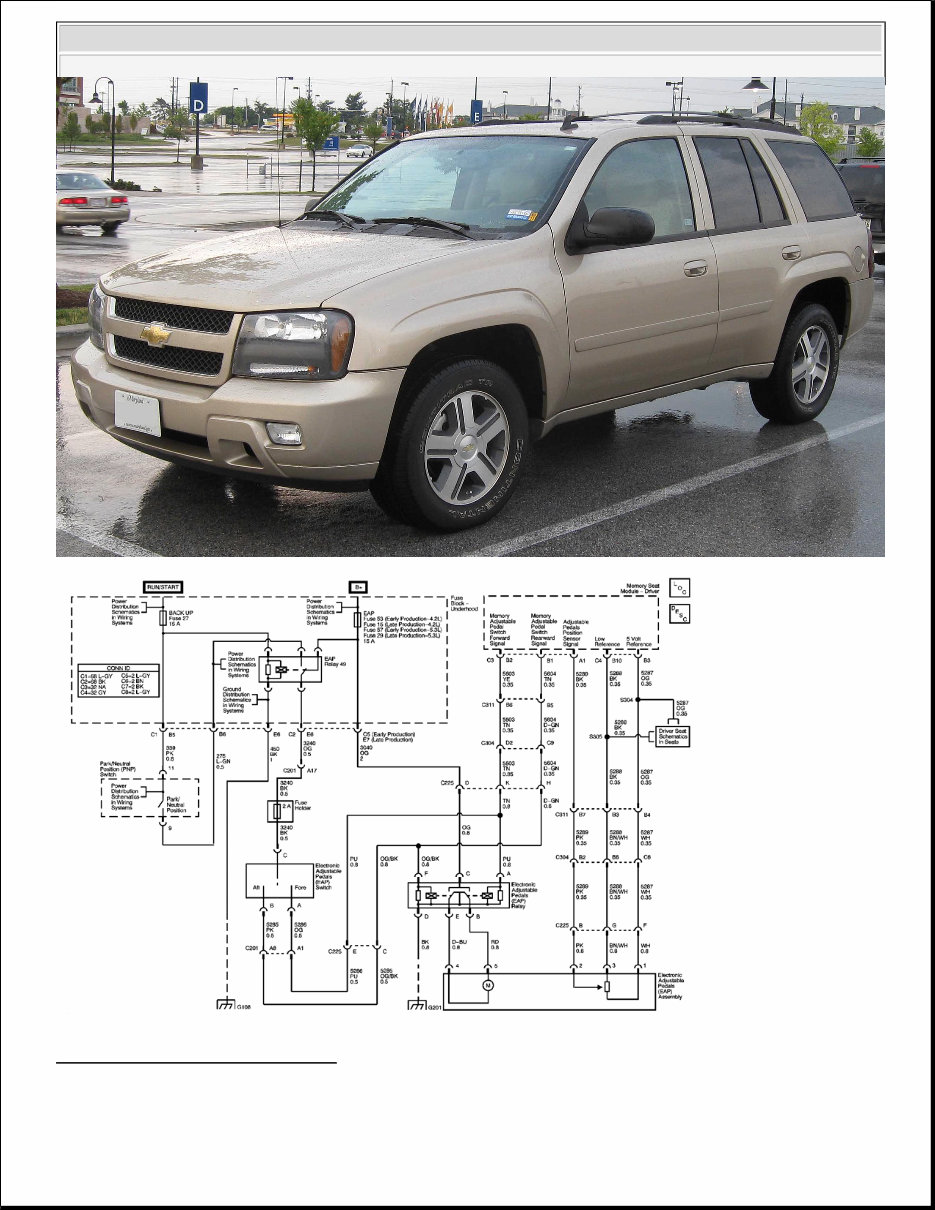
ADJUSTABLE PEDALS SCHEMATICS
Fig. 1: Adjustable Pedals Schematic
Courtesy of GENERAL MOTORS CORP.
Application
Specification
Metric English
Accelerator Mounting Nut 11 N.m 98 lb in
Brake Pedal Pivot Bolt 25 N.m 19 lb ft
Brake Pedal Sensor Bolt 9 N.m 80 lb in
2002-2009 Chevrolet TrailBlazer
REPAIR MANUAL
COMPONENT LOCATOR
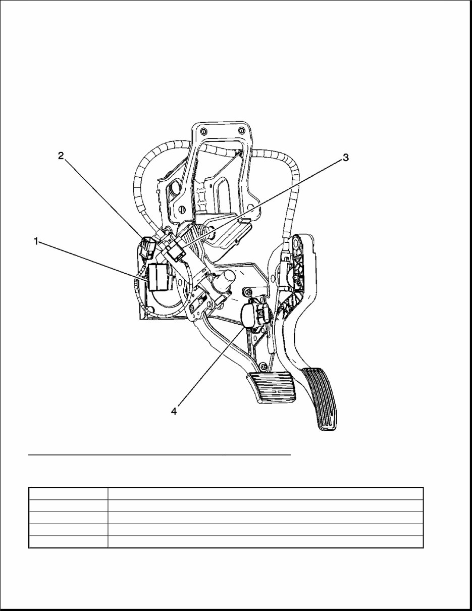
ADJUSTABLE PEDALS COMPONENT VIEWS
Fig. 2: Lower LF of the Passenger Compartment - Pedal Assembly
Courtesy of GENERAL MOTORS CORP.
Callouts For Fig. 2
Callout Component Name
1 Electronic Adjustable Pedals (EAP) Relay
2 C225
3 Electronic Adjustable Pedals (EAP) Assembly Connector
4 Accelerator Pedal Position (APP) Sensor
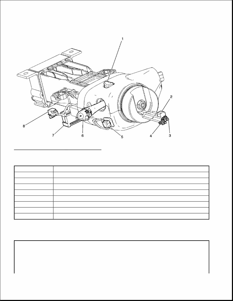
Fig. 3: Left Side of the I/P - Steering Column
Courtesy of GENERAL MOTORS CORP.
Callouts For Fig. 3
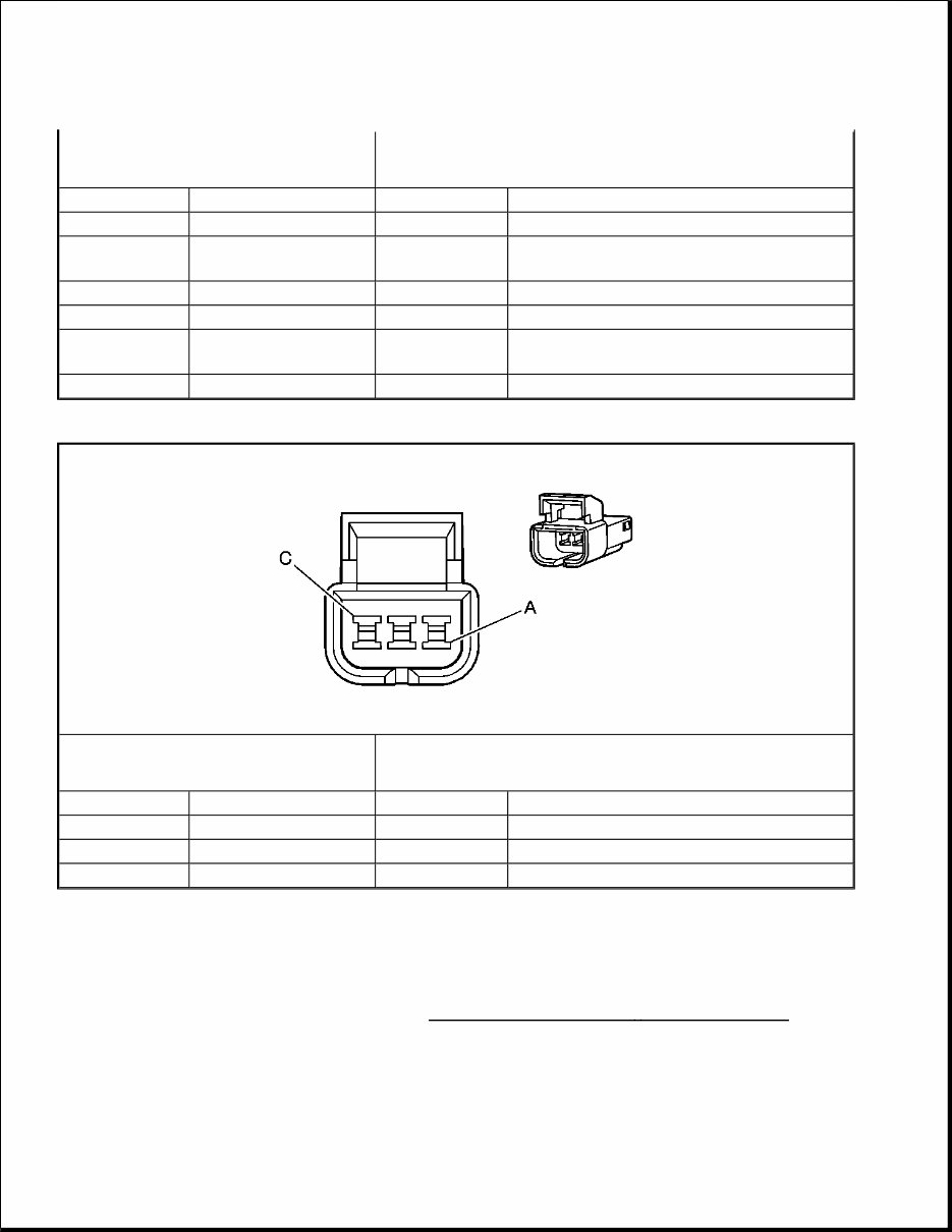
ADJUSTABLE PEDALS CONNECTOR END VIEWS
Electronic Adjustable Pedals (EAP) Assembly
Callout Component Name
1 Hazard Switch
2 Inflatable Restraint Steering Wheel Module Coil Connector C4
3 Inflatable Restraint Steering Wheel Module Coil Connector C2
4 Inflatable Restraint Steering Wheel Module Coil Connector C3
5 Electronic Adjustable Pedals (EAP) Switch
6 Turn Signal/Multifunction Switch
7 C201
8 Inflatable Restraint Steering Wheel Module Coil Connector C1
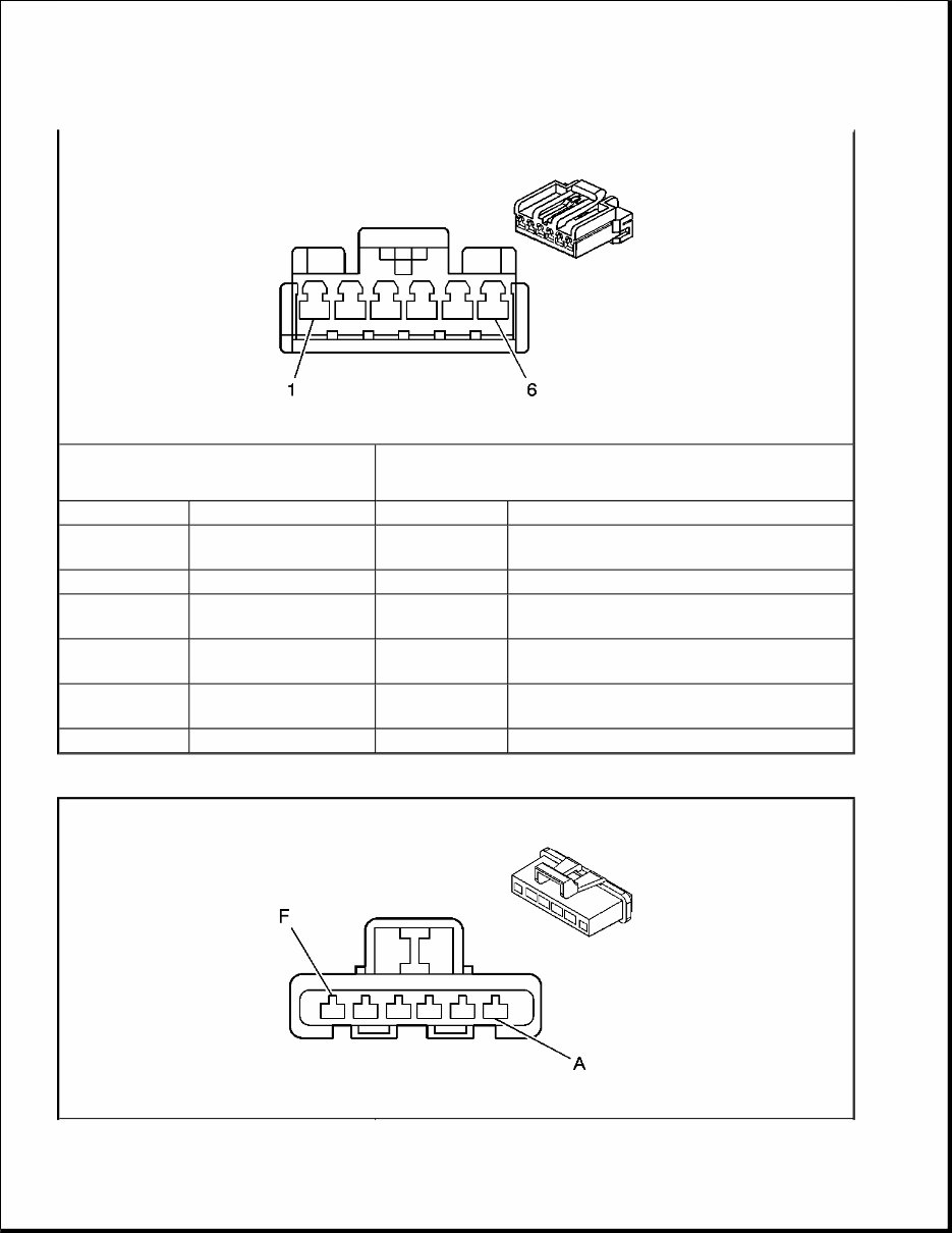
Electronic Adjustable Pedals (EAP) Relay
Connector Part Information
174923-1
6-Way F Amp Multilock 070 Series (BK)
Pin Wire Color Circuit No. Function
1 WH 5287
Adjustable Pedals Position Sensor 5-Volt
Reference
2 PK 5289 Adjustable Pedals Position Sensor Signal
3 BN/WH 5288
Adjustable Pedals Position Sensor Low
Reference
4 D-BU -
Electronic Adjustable Pedals (EAP) Motor
Rearward Control
5 RD -
Electronic Adjustable Pedals (EAP) Motor
Forward Control
6 - - Not Used
Electronic Adjustable Pedals (EAP) Switch
DIAGNOSTIC INFORMATION AND PROCEDURES
DIAGNOSTIC STARTING POINT - ADJUSTABLE PEDALS (WITH MEMORY)
Begin adjustable pedal system diagnosis with the Diagnostic System Check - Adjustable Pedals . The
Diagnostic System Check will provide the following information:
The identification of the control modules which command the system.
The ability of the control modules to communicate through the serial data circuit.
Connector Part Information
12059561
6-Way F Metri-Pack Connectors, Mixed Series (BK)
Pin Wire Color Circuit No. Function
A PU 5286 Adjustable Pedals Relay Forward Control
B RD -
Electronic Adjustable Pedals (EAP) Motor
Forward Control
C OG 3040 Battery Positive Voltage
D BK 2250 Ground
E D-BU -
Electronic Adjustable Pedals (EAP) Motor
Rearward Control
F OG/BK 5285 Adjustable Pedals Relay Rearward Control
Connector Part Information
12064759
3-Way M Metri-Pack 150 Series (BK)
Pin Wire Color Circuit No. Function
A OG 5286 Adjustable Pedals Relay Forward Control
B PK 5285 Adjustable Pedals Relay Rearward Control
C BK 3240 Battery Positive Voltage

The identification of any stored diagnostic trouble codes (DTCs) and their status.
The use of the Diagnostic System Check will identify the correct procedure for diagnosing the system and
where the procedure is located.
DIAGNOSTIC STARTING POINT - ADJUSTABLE PEDALS (W/O MEMORY)
Begin the adjustable pedal system diagnosis by reviewing the system Description and Operation. Reviewing the
Description and Operation information will help you determine the correct symptom diagnostic procedure when
a malfunction exists. Reviewing the Description and Operation information will also help you determine if the
condition described by the customer is normal operation. Refer to Symptoms - Seats in order to identify the
correct procedure for diagnosing the system and where the procedure is located.
DIAGNOSTIC SYSTEM CHECK - ADJUSTABLE PEDALS
Test Description
The numbers below refer to the step numbers on the diagnostic table.
2: Lack of communication may be due to a partial malfunction of the class 2 serial data circuit or due to a
total malfunction of the class 2 serial data circuit. The specified procedure will determine the particular
condition.
5: The presence of DTCs which begin with "U" indicate some other module is not communicating. The
specified procedure will compile all the available information before tests are performed.
Diagnostic System Check - Adjustable Pedals
Step Action Yes No
1
Install a scan tool.
Does the scan tool power up?
Go to Step 2
Go to Scan Tool
Does Not Power
Up in Data Link
Communications
2
Attempt to establish communication with the following
control modules:
Driver seat module
Driver door module
Does the scan tool communicate with the listed control
modules?
Go to Step 3
Go to Scan Tool
Does Not
Communicate
with Class 2
Device (W/O
Immobilizer) Scan
Tool Does Not
Communicate
with Class 2
Device (W/
Immobilizer) in
Data Link
Communications
IMPORTANT:
The engine may start during the following step. Turn
SCAN TOOL DATA LIST
Driver Seat Module
3
1. Access the Class 2 Power Mode in the Diagnostic
Circuit Check on the scan tool.
2. Rotate the ignition switch through all positions
while observing the ignition switch power mode
parameter.
Does the ignition switch parameter reading match the
ignition switch position for all switch positions?
OFF the engine as soon as you have observed the
Crank power mode.
Go to Step 4
Go to Power Mode
Mismatch in Body
Control System
4
Select the display DTCs function on the scan tool for the
following control modules:
Driver seat module
Driver door module
Does the scan tool display any DTCs? Go to Step 5
Go to Diagnostic
Trouble Code
(DTC) List
5
Does the scan tool display any DTC that begins with a
"U"?
Go to Scan Tool
Does Not
Communicate
with Class 2
Device (W/O
Immobilizer) Scan
Tool Does Not
Communicate
with Class 2
Device (W/
Immobilizer) in
Data Link
Communications Go to Step 6
6
Does the scan tool display B1000? Go to Diagnostic
Trouble Code
(DTC) List in
Body Control
System
Go to Symptoms -
Adjustable Pedals
Scan Tool Parameter Data List Units Displayed Typical Data Value
Operating Conditions: Ignition Off
Pedal Position Sensor Data Volts 0.0-5.0

SCAN TOOL DATA DEFINITIONS
Driver Seat Module
Pedal Position
The scan tool displays 0.0-5.0 volts. The voltage displayed is the input to the driver seat module from the
adjustable pedal motor position sensor.
DIAGNOSTIC TROUBLE CODE (DTC) LIST
Diagnostic Trouble Code (DTC) List
DTC B3606
Circuit Description
The driver seat module monitors the location of the adjustable pedals using the brake pedal position sensor. The
brake pedal position sensor is supplied with 5-volt reference and ground circuits from the driver seat module.
The position sensor signal circuit is referenced from ground within the driver seat module. The signal voltage
monitored by the driver seat module ranges from 0.39-4.58 volts and is determined by the wiper location on the
resistor within the position sensor. The position sensor circuit voltage level is used by the driver seat module to
determine the position of the adjustable pedals when storing or recalling memory position settings.
Conditions for Running the DTC
Battery voltage to the seat module must be within 7-16 volts.
Conditions for Setting the DTC
The position sensor signal circuit voltage level to the driver seat module is not within the 0.39-4.58 volt range.
Action Taken When the DTC Sets
The memory recall functions will be disabled for as long as the DTC is current.
Conditions for Clearing the DTC
The DTC will be stored as a history code when the fault is no longer present.
A history DTC will be cleared after completing 100 consecutive ignition cycles, or by using the scan tool
clearing DTCs feature.
Diagnostic Aids
DTC Diagnostic Procedure Modules
B3606 DTC B3606 Driver Seat Module
B3607 DTC B3607 Driver Seat Module

If the DTC is only found in history, the fault may be intermittent. Refer toTesting for Intermittent Conditions
and Poor Connections in Wiring Systems.
Test Description
The numbers below refer to the step numbers on the diagnostic table.
3: Tests for the proper operation of the circuit in the low voltage range.
4: Tests for the proper operation of the circuit in the high voltage range. If the fuse in the jumper opens if
you perform this test, the signal circuit is short to ground.
5: Tests for a short to voltage in the 5-volt reference circuit.
DTC B3606
Step Action Values Yes No
Schematic Reference: Adjustable Pedals Schematics
Connector End View Reference: Adjustable Pedals Connector End Views
1
Did you perform the Adjustable Pedal
Diagnostic System Check?
-
Go to Step 2
Go to
Diagnostic
System Check
- Adjustable
Pedals
2
1. Install a scan tool.
2. With a scan tool, observe the brake pedal
position sensor parameter in the seat
module Adjustable Pedal data list.
Is the position sensor parameter within the
specified range?
0.39-4.58 V
Go to Testing
for
Intermittent
Conditions and
Poor
Connections in
Wiring Systems Go to Step 3
3
1. Disconnect the position sensor connector.
2. With a scan tool, observe the position
sensor parameter.
Is the position sensor parameter less than the
specified value?
0.39 V
Go to Step 4 Go to Step 8
4
1. Connect a 3-amp fused jumper wire
between the 5-volt reference circuit
terminal and the signal circuit terminal in
the position sensor harness connector.
2. With a scan tool, observe the position
sensor parameter.
Is the position sensor parameter greater than the
specified value?
4.58 V
Go to Step 5 Go to Step 7
1. Disconnect the fused jumper wire.

5
2. Measure the voltage between the 5-volt
reference circuit terminal and the low
reference circuit terminal in the position
sensor harness connector.
Is the voltage measure greater than the specified
value?
5.0 V
Go to Step 6 Go to Step 10
6
Test the 5-volt reference circuit for a short to
voltage. Refer to Circuit Testing and to Wiring
Repairs in Wiring Systems.
Did you find and correct the condition?
-
Go to Step 15 Go to Step 12
7
Test the 5-volt reference circuit for one of the
following conditions:
A short to ground
A high resistance
An open
Refer to Circuit Testing and to Wiring Repairs
in Wiring Systems.
Did you find and correct the condition?
-
Go to Step 15 Go to Step 9
8
Test the signal circuit of the position sensor for a
short to voltage. Refer to Circuit Testing and to
Wiring Repairs in Wiring Systems.
Did you find and correct the condition?
-
Go to Step 15 Go to Step 12
9
Test the signal circuit of the position sensor for
one of the following conditions:
A short to ground
A high resistance
An open
Refer to Circuit Testing and to Wiring Repairs
in Wiring Systems.
Did you find and correct the condition?
-
Go to Step 15 Go to Step 12
10
Test the low reference circuit of the position
sensor for an open or high resistance. Refer to
Circuit Testing and to Wiring Repairs in
Wiring Systems.
Did you find and correct the condition?
-
Go to Step 15 Go to Step 11
Inspect for poor connections at the brake pedal
position sensor. Refer to Testing for
Intermittent Conditions and Poor
You're Reading a Preview
What's Included?
Fast Download Speeds
Online & Offline Access
Access PDF Contents & Bookmarks
Full Search Facility
Print one or all pages of your manual
$36.99
Viewed 27 Times Today


Secure transaction
What's Included?
Fast Download Speeds
Online & Offline Access
Access PDF Contents & Bookmarks
Full Search Facility
Print one or all pages of your manual
$36.99
This manual is a comprehensive guide for maintaining and fixing various issues with the 2006 Chevrolet Trailblazer. It is a valuable resource for both professional mechanics and DIY enthusiasts. The manual provides detailed instructions and diagrams covering routine maintenance to major repairs, including troubleshooting, disassembly, reassembly, and adjustments for all models of the 2006 Chevrolet Trailblazer.
Models covered in this manual:
- 2006 Chevrolet Trailblazer Base Sport Utility 4-Door
- 2006 Chevrolet Trailblazer LS Sport Utility 4-Door
- 2006 Chevrolet Trailblazer EXT LS Sport Utility 4-Door
- 2006 Chevrolet Trailblazer LT Sport Utility 4-Door
- 2006 Chevrolet Trailblazer EXT LT Sport Utility 4-Door
Whether it's routine maintenance tasks like oil changes and brake pad replacements or more complex repairs like engine overhauls and electrical troubleshooting, this manual is a valuable resource to keep your 2006 Chevrolet Trailblazer running smoothly.


