

2000 TRACKER Service and Repair Manual
What's Included?
Fast Download Speeds
Offline Viewing
Access Contents & Bookmarks
Full Search Facility
Print one or all pages of your manual
1999-2000 ENGINES
1.6L 4-Cylinder
ENGINE IDENTIFICATION
Engine can be identified by sixth character of Vehicle Identification Number (VIN) located on
top of dash panel, at lower left corner of windshield.
ENGINE IDENTIFICATION CODE
ADJUSTMENTS
VALVE CLEARANCE
1. Disconnect negative battery cable. Remove air cleaner assembly and valve cover. Rotate
crankshaft until cylinder No. 1 is at TDC of compression stroke. Ensure timing "V" mark on
crankshaft pulley aligns with "0" mark on timing belt cover.
2. Remove distributor cap. Ensure rotor aligns with cylinder No. 1 distributor terminal. If
rotor is not aligned with cylinder No. 1 distributor terminal, rotate crankshaft pulley
clockwise 360 degrees.
3. Measure clearance between adjustment screw and valve stem using a feeler gauge. Check
clearance of intake valves of cylinders No. 1 and 2, and exhaust valves of cylinders No. 1
and 3.
4. Rotate crankshaft clockwise 360 degrees. Check clearance of intake valves of cylinders No.
3 and 4, and exhaust valves of cylinders No. 2 and 4.
5. Adjust valve clearance if not within specification. See VALVE CLEARANCE
SPECIFICATIONS table. Adjust clearance by loosening adjusting screw lock nut and
rotating adjusting screw. Tighten adjusting screw lock nut to 13 ft. lbs. (18 N.m) while
holding adjusting screw.
NOTE: Information for 1999 Tracker is unavailable. For repair procedures
not covered in this article, see ENGINE OVERHAUL PROCEDURES
article in GENERAL INFORMATION.
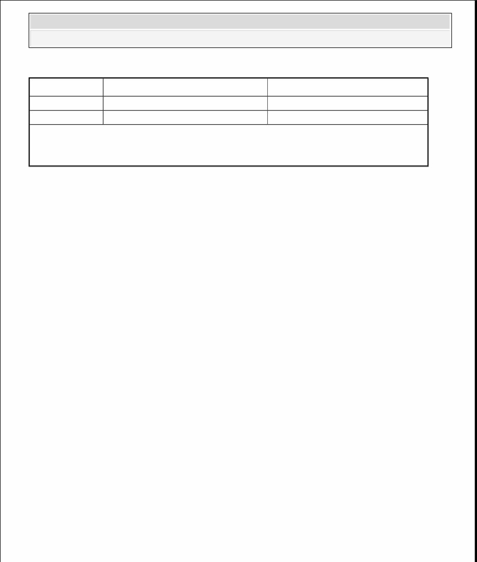
Application VIN
1.6L 4-Cylinder 16-Valve 6
NOTE: Valve clearance can be adjusted with engine cold or hot.
2000 Chevrolet Tracker
1999-2000 ENGINES 1.6L 4-Cylinder
2000 Chevrolet Tracker
1999-2000 ENGINES 1.6L 4-Cylinder
VALVE CLEARANCE SPECIFICATIONS
TROUBLE SHOOTING
REMOVAL & INSTALLATION
FUEL PRESSURE RELEASE
1. Place transmission in Neutral (M/T) or Park (A/T). Set parking brake, and block wheels.
Loosen fuel tank cap to release fuel tank pressure. Disconnect fuel pump relay connector
located in right side center console (gain access through glove box). Start engine, and allow
engine to stall. Crank engine again for an addition 3 seconds to ensure relief of any
remaining pressure.
2. Disconnect negative battery cable. Connect fuel pump relay connector, and tighten fuel
filler cap. Cover fuel line or component to be disconnected with shop rag during removal
procedure.
ENGINE
Valve
(1)
Hot - In. (mm)
(2)
Cold - In. (mm)
Intake .007-.008 (.18-.20) .005-.007 (.13-.18)
Exhaust .011-.013 (.28-.32) .009-.011 (.23-.27)
(1)
With engine coolant temperature greater than 154°F (68°C).
(2)
With engine coolant temperature less than 77°F (25°C).
NOTE: To trouble shoot engine mechanical components, see appropriate
table in TROUBLE SHOOTING article in GENERAL INFORMATION.
NOTE: For repair procedures not covered in this article. See ENGINE
OVERHAUL PROCEDURES article in GENERAL INFORMATION.
NOTE: For reassembly reference, label all electrical connectors, vacuum
hoses and fuel lines before removal. Also place mating marks on
engine hood and other major assemblies before removal.
CAUTION: Always relieve fuel pressure before disconnection of any fuel
injection-related component. Do not allow fuel to contact
engine or electrical components.
2000 Chevrolet Tracker
1999-2000 ENGINES 1.6L 4-Cylinder

Removal
1. Release fuel pressure. See FUEL PRESSURE RELEASE . Mark and remove hood.
Disconnect battery cables. Drain cooling system and engine oil.
2. On A/T models, disconnect transmission oil cooler lines. Remove cooling fan and clutch, fan
shroud and radiator. It may be possible to remove A/C condenser and compressor (if
equipped) and lay aside to gain clearance, leaving hoses connected. If not, evacuate A/C
system using approved recovery/recycling equipment, and remove components as necessary.
Remove air cleaner and air intake tubing. Disconnect accelerator cable and kickdown cable
(if equipped).
3. Disconnect power steering hoses and drain fluid. Disconnect necessary electrical
connections, vacuum hoses, fuel lines and coolant hoses. Raise and support vehicle. Remove
skid plate. Remove starter motor. Disconnect exhaust pipe from exhaust manifold.
4. On M/T models, disconnect clutch cable from bracket near starter motor. On A/T models,
remove torque converter housing lower plate and torque converter-to-flexplate bolts.
5. On all models, lower vehicle. Support transmission. Remove transmission-to-cylinder block
bolts. Mark distributor housing position in relation to cylinder head, and remove distributor.
Install chain hoist to engine. Remove engine mount bolts, and remove engine.
Installation
To install, reverse removal procedure. Install a NEW rear main seal. Apply Loctite (414) to
flywheel retaining bolt threads. Tighten all fasteners to specification. See TORQUE
SPECIFICATIONS . Adjust all control cables. Adjust all fluid levels.
INTAKE MANIFOLD
Removal
1. Disconnect negative battery cable. Release fuel pressure. See FUEL PRESSURE
RELEASE . Drain cooling system. Remove air cleaner assembly.
2. Label and disconnect necessary electrical connections, fuel lines, coolant hoses, vacuum
hoses and control cables from throttle body and intake manifold. Remove intake manifold
bolts and nuts, intake manifold and gasket.
Installation
To install, reverse removal procedure. Tighten bolts and nuts to specification. See TORQUE
NOTE: Leave transmission in vehicle when removing engine.
2000 Chevrolet Tracker
1999-2000 ENGINES 1.6L 4-Cylinder

SPECIFICATIONS . Adjust all control cables. Refill cooling system.
EXHAUST MANIFOLD
Removal & Installation
1. Disconnect negative battery cable and oxygen sensor connector. Remove air cleaner
bracket. Remove covers from exhaust manifold. Disconnect exhaust pipe at exhaust
manifold. Remove retaining bolts and nuts, exhaust manifold and gasket.
2. To install, reverse removal procedure. Tighten bolts and nuts to specification. See
TORQUE SPECIFICATIONS .
CYLINDER HEAD
Removal
1. Release fuel pressure. See FUEL PRESSURE RELEASE . Disconnect negative battery
terminal. Drain cooling system.
2. Remove air cleaner assembly. Label and disconnect necessary electrical connections, fuel
lines, coolant hoses, vacuum hoses and control cables from distributor, throttle body and
intake manifold.
3. Remove intake manifold with gasket, intake surge tank and throttle body. Remove exhaust
manifold heat shield. Raise vehicle and disconnect exhaust pipe from exhaust manifold.
Lower vehicle and remove exhaust manifold. Remove cooling fan, water pump pulley and
cooling fan shroud.
4. Before removing timing belt, ensure timing marks are aligned. Remove timing belt. See
TIMING BELT . Using Camshaft Gear Spanner Wrench (J-41840), remove camshaft
timing belt gear.
5. If equipped with A/C, loosen compressor support brackets and clamps, and without
discharging system, position compressor aside. Remove valve cover. Remove distributor,
valve cover and distributor case. Loosen all valve adjusting screw lock nuts and adjusting
screws until rocker arms are loose, to ensure all valves are closed.
6. Remove camshaft. See CAMSHAFT . Loosen cylinder head bolts in reverse order of
tightening sequence. See Fig. 1 . Loosen head bolts evenly in 3 steps to prevent cylinder
CAUTION: Camshaft can be damaged if camshaft carrier bolts are
removed randomly. Loosen camshaft carrier cap bolts
gradually in reverse order of tightening sequence. See
Fig. 6 .
2000 Chevrolet Tracker
1999-2000 ENGINES 1.6L 4-Cylinder

head warpage. Remove cylinder head bolts, cylinder head and gasket.
Inspection
1. Inspect cylinder head surface for warpage. Inspect cylinder head manifold seating surfaces
for warpage. Replace cylinder head if warpage cannot be corrected by resurfacing. See
CYLINDER HEAD table under ENGINE SPECIFICATIONS.
2. Inspect cylinder block deck surface for warpage. Resurface cylinder block if warpage
exceeds specification. See CYLINDER BLOCK table under ENGINE
SPECIFICATIONS.
3. Inspect cylinder head oil jet for obstructions. Oil jet is located at timing belt end of head, in
head-to-block mating surface. See Fig. 2 . Tighten oil jet to 44 INCH lbs. (5 N.m).
Installation
1. To install, reverse removal procedure. Lubricate cylinder head bolts with engine oil before
installing. Tighten cylinder head bolts to specification, in 3 steps, in sequence. Tighten
cylinder head bolts to specified torque during each pass. See Fig. 1 . See TORQUE
SPECIFICATIONS .
2. Apply RTV sealant to bottom of camshaft cap No. 6 (cap closest to distributor drive gear).
Install camshaft and camshaft carrier caps. See CAMSHAFT . Ensure timing marks are in
correct alignment. See Fig. 4 . Adjust valve clearance. See VALVE CLEARANCE under
ADJUSTMENTS.
3. Apply RTV sealant to surface of distributor case that mates with rear of rocker arm shaft.
Install distributor case and tighten 3 bolts to specification. To install remaining components,
reverse removal procedure. Tighten bolts and nuts to specification. See TORQUE
SPECIFICATIONS .
4. Adjust all control cables. Refill cooling system, and check engine oil level.
2000 Chevrolet Tracker
1999-2000 ENGINES 1.6L 4-Cylinder
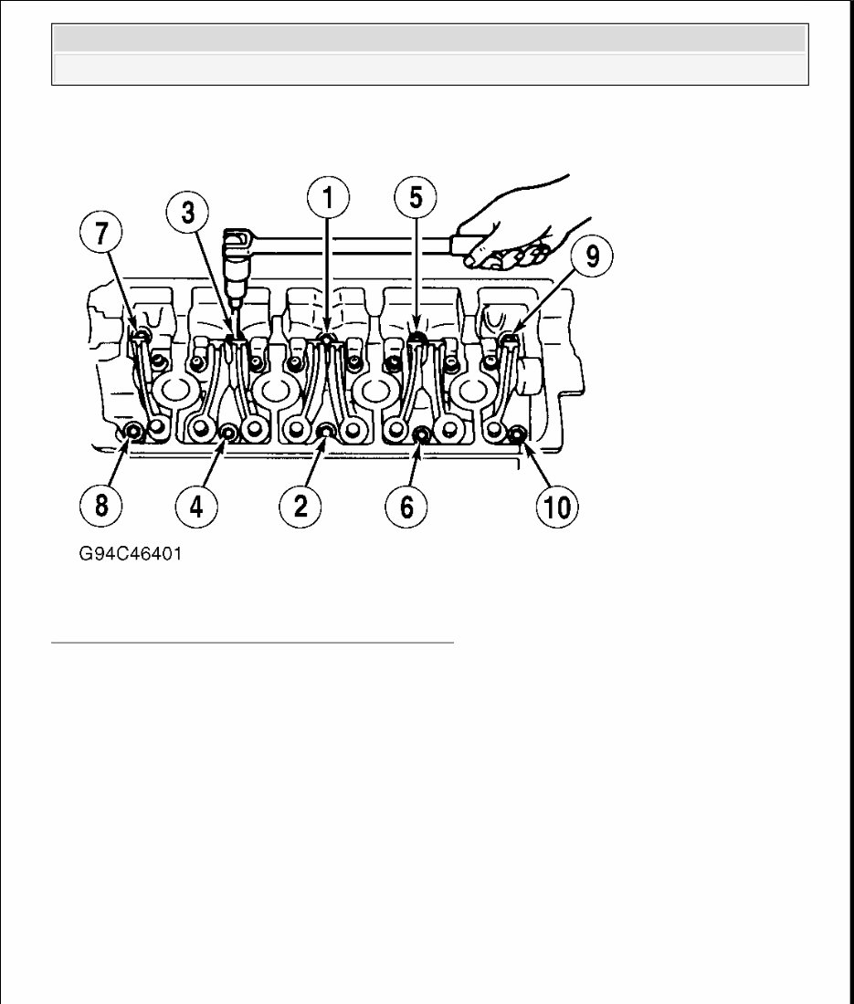
Fig. 1: Cylinder Head Bolt Tightening Sequence
Courtesy of GENERAL MOTORS CORP.
2000 Chevrolet Tracker
1999-2000 ENGINES 1.6L 4-Cylinder
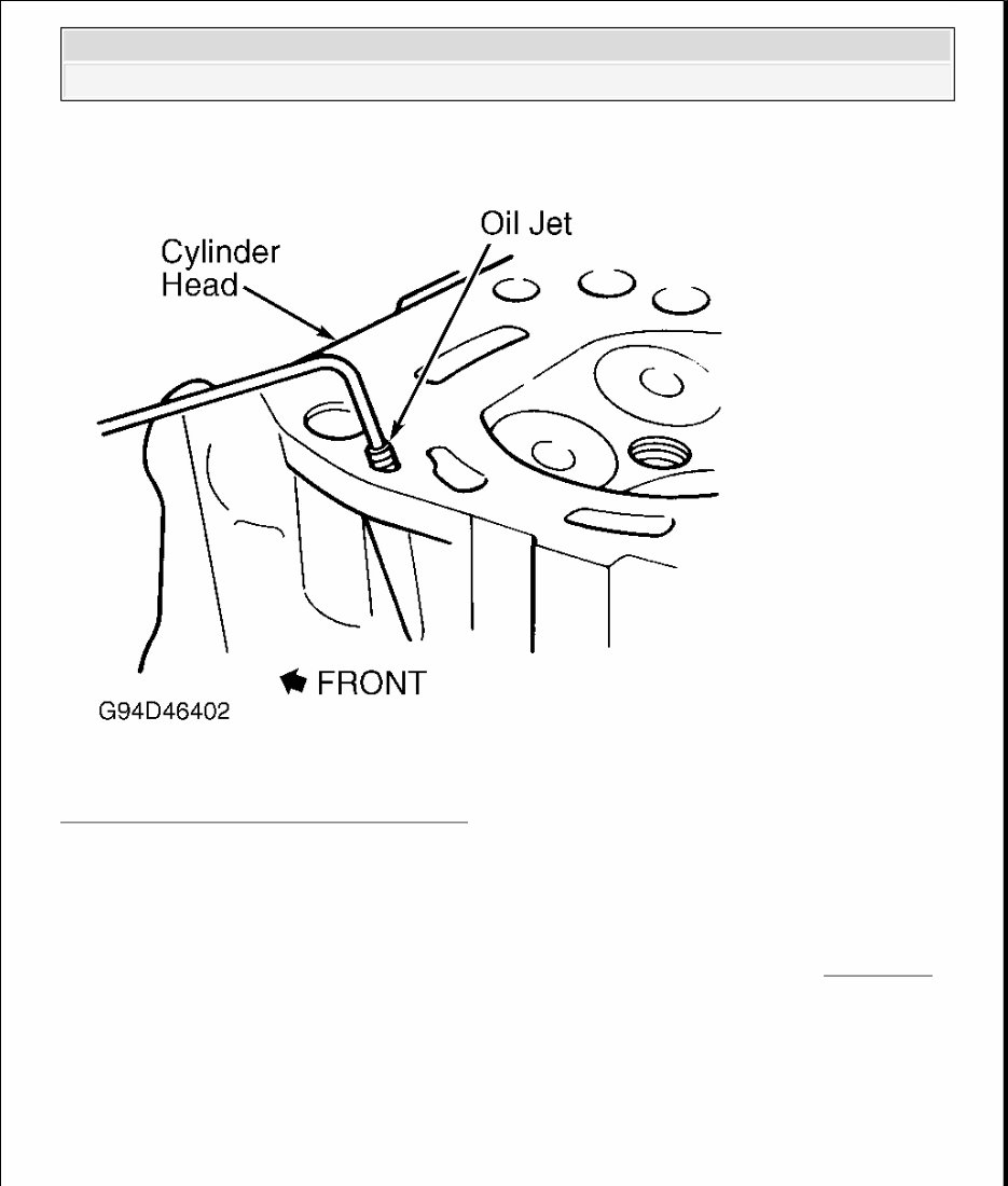
Fig. 2: Locating Oil Jet In Cylinder Head
Courtesy of GENERAL MOTORS CORP.
CRANKSHAFT FRONT SEAL
TIMING BELT
Removal
1. Disconnect negative battery cable. Remove accessory drive belts. Remove cooling fan, fan
shroud and water pump pulley.
NOTE: Crankshaft front seal is mounted in oil pump housing. Manufacturer
lists replacement procedure with oil pump removed. See OIL PUMP
under ENGINE OILING.
2000 Chevrolet Tracker
1999-2000 ENGINES 1.6L 4-Cylinder

2. Remove outer bolts retaining crankshaft pulley. Remove crankshaft pulley. It is not
necessary to remove center bolt from crankshaft pulley. Raise vehicle and remove skid plate
(if equipped).
3. Remove timing belt cover and seal. See Fig. 3 . Ensure timing marks are aligned before
removing timing belt (camshaft sprocket timing mark "E" is aligned with notch in valve
cover, and crankshaft timing gear punch mark is aligned with arrow on oil pump housing). If
reusing timing belt, ensure direction of belt rotation is marked for installation reference. On
all models, remove tensioner spring and tensioner stud. Loosen tensioner bolt. DO NOT
remove tensioner bolt.
4. Push tensioner plate upward, and remove timing belt. If removing crankshaft sprocket,
remove retaining bolt, crankshaft sprocket, key and timing belt guide (located behind
crankshaft sprocket) from crankshaft.
5. If removing camshaft sprocket, remove valve cover. Use Camshaft Sprocket Spanner
Wrench (J-41840) to hold camshaft during camshaft sprocket removal. On all models,
remove retaining bolt and camshaft sprocket.
CAUTION: Do not rotate either camshaft or crankshaft with timing
belt removed, piston/valve interference may cause
component damage.
2000 Chevrolet Tracker
1999-2000 ENGINES 1.6L 4-Cylinder
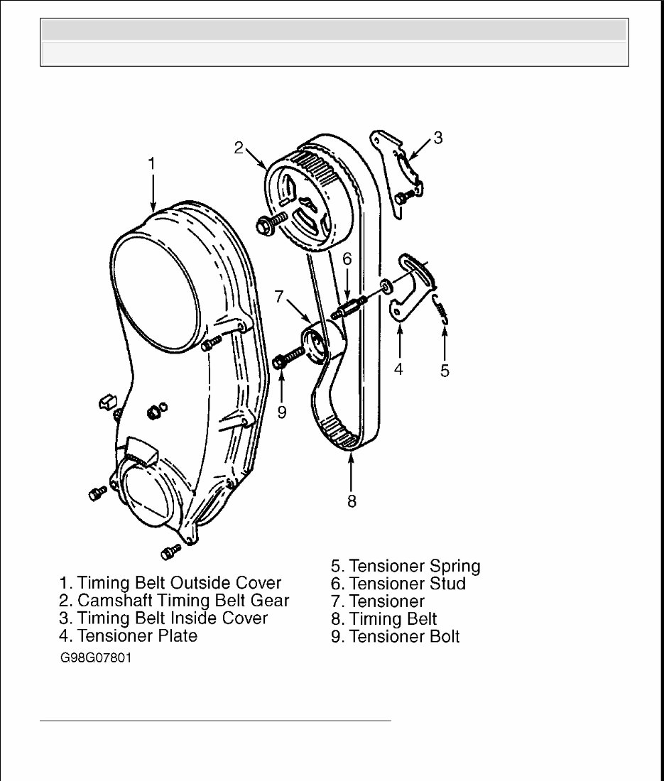
Fig. 3: Exploded View Of Timing Belt & Components
Courtesy of GENERAL MOTORS CORP.
Inspection
2000 Chevrolet Tracker
1999-2000 ENGINES 1.6L 4-Cylinder

Inspect timing belt for damaged teeth or cracking. Ensure timing belt is not contaminated with
oil. Check tensioner for smooth rotation. Replace components if damaged.
Installation
1. Install timing belt inside cover and seal (if removed). Install timing belt tensioner plate and
tensioner. Finger tighten tensioner stud and bolt.
2. Install camshaft sprocket (if removed). Ensure sprocket aligns with pin in camshaft. Tighten
camshaft sprocket retaining bolt to specification. See TORQUE SPECIFICATIONS .
3. Push timing belt tensioner plate up, and install timing belt onto camshaft sprocket and
crankshaft timing gear. Install timing belt so arrow on timing belt aligns with direction of
crankshaft rotation. Ensure there is no slack on right side of timing belt. Ensure timing
marks are aligned. See Fig. 4 . Install tensioner spring to timing belt tensioner plate.
4. Rotate crankshaft clockwise 2 complete revolutions to remove timing belt slack and to seat
timing belt. Ensure timing marks are in alignment (camshaft sprocket timing mark "E" is
aligned with notch in valve cover, and crankshaft timing gear punch mark is aligned with
arrow on oil pump housing). See Fig. 4 .
5. Tighten tensioner stud and bolt to specification. See TORQUE SPECIFICATIONS .
Ensure all timing marks align. To install remaining components, reverse removal procedure.
CAUTION: Ensure tensioner plate moves when tensioner is moved
toward timing belt. If tensioner plate does not move,
ensure lug engages in tensioner hole.
2000 Chevrolet Tracker
1999-2000 ENGINES 1.6L 4-Cylinder
You're Reading a Preview
What's Included?
Fast Download Speeds
Offline Viewing
Access Contents & Bookmarks
Full Search Facility
Print one or all pages of your manual
$36.99
Viewed 84 Times Today


Secure transaction
What's Included?
Fast Download Speeds
Offline Viewing
Access Contents & Bookmarks
Full Search Facility
Print one or all pages of your manual
$36.99
The 2000 TRACKER Service and Repair Manual is a comprehensive guide that provides detailed instructions and information for maintaining and fixing your 2000 TRACKER model. This manual is designed to assist both professional mechanics and DIY enthusiasts in effectively addressing any issues that may arise with their vehicle.
Key Features:
- Step-by-step instructions for performing various repairs and services on your 2000 TRACKER model
- Detailed diagrams and illustrations to aid in the understanding of the repair procedures
- Comprehensive information on the vehicle's systems, including engine, transmission, suspension, and electrical
- Troubleshooting guides to help diagnose and solve common problems
- Maintenance schedules and procedures to keep your 2000 TRACKER in optimal condition
With the 2000 TRACKER Service and Repair Manual, you can confidently tackle any maintenance or repair task on your own. Save time and money by avoiding costly visits to the mechanic and get your vehicle back on the road in no time.


