2004 Chevrolet Suburban 2500 Service & Repair Manual Software
What's Included?
Lifetime Access
Fast Download Speeds
Online & Offline Access
Access PDF Contents & Bookmarks
Full Search Facility
Print one or all pages of your manual
2000 Chevrolet Suburban C1500 2000-01 DRIVE AXLES 4WD Steering Knuckles 2000-01 DRIVE AXLES 4WD Steering Knuckles MODEL IDENTIFICATION MODEL IDENTIFICATION Series (l) Model "K" 4WD Pickup, Sierra, Silverado, Suburban, Tahoe, Yukon & AWD Escalade "L" AWD Astro & Safari "T" 4WD Blazer, Envoy, Jimmy, Pickup, Sonoma, & AWD Bravada (1) Vehicle series is fifth character ofVIN. REMOVAL & INSTALLATION STEERING KNUCKLE Removal 1. Raise and support vehicle. Remove wheel and tire assembly. Install Axle Shaft Boot Seal Protector (J-28712) on axle shaft boot to protect boot during repair. Detach and depress brake caliper piston, and wire aside. Remove brake rotor. 2. Remove cotter pin and retainer (if equipped) from axle shaft nut. Remove nut and washer from axle shaft. Remove cotter pin and tie rod end nut. Separate tie rod end from steering knuckle. See Fig. 1 . 3. Attach puller to hub. Tighten pressure screw, and force axle shaft from hub and bearing assembly. Remove hub and bearing assembly from steering knuckle. Remove splash shield. CAUTION: Support lower control arm with floor jack or jackstand to maintain tension on torsion bar. J
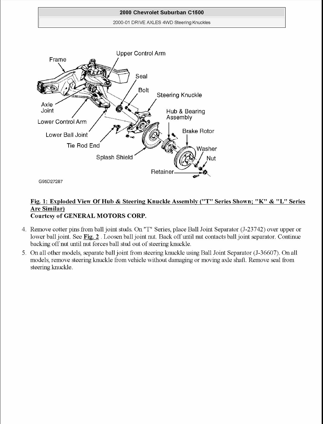
G95D27287 Tie Rod End 2000 Chevrolet Suburban C1500 2000-01 DRIVE AXLES 4WD Steering Knuckles Upper Control Arm Steering Knuckle Hub & Bearing Assembly , Brake Rotor ':. Splash Shield Fig. 1: Exploded View Of Hub & Steering Knuckle Assembly ("T" Series Shown; "K" & "L" Series Are Similar) Courtesy of GENERAL MOTORS CORP. 4. Remove cotter pins from ball joint studs. On "T" Series, place Ball Joint Separator (J-23742) over upper or lower ball joint. See Fig. 2. Loosen ball joint nut. Back offuntil nut contacts ball joint separator. Continue backing off nut until nut forces ball stud out of steering knuckle. 5. On all other models, separate ball joint from steering knuckle using Ball Joint Separator (J-36607). On all models, remove steering knuckle from vehicle without damaging or moving axle shaft. Remove seal from steering knuckle.
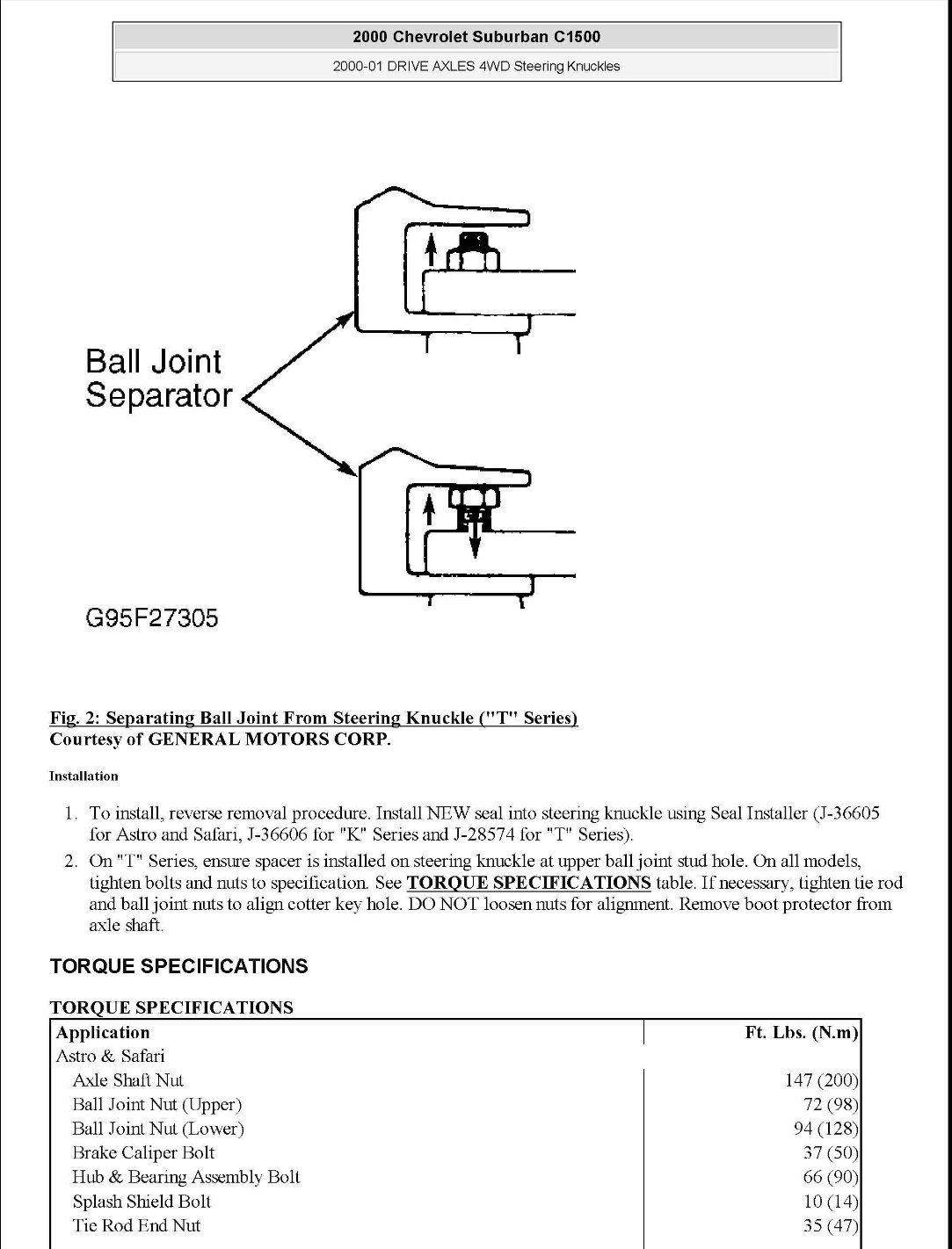
Ball Joint Separator G95F27305 2000 Chevrolet Suburban C1500 2000-01 DRIVE AXLES 4WD Steering Knuckles Fig. 2: Separating Ball Joint From Steering Knuckle ("T" Series) Courtesy of GENERAL MOTORS CORP. Installation 1. To install, reverse removal procedure. Install NEW seal into steering knuckle using Seal Installer (J-36605 for Astro and Safari, J-36606 for "K" Series and J-28574 for "T" Series). 2. On "T" Series, ensure spacer is installed on steering knuckle at upper ball joint stud hole. On all models, tighten bolts and nuts to specification See TORQUE SPECIFICATIONS table. If necessary, tighten tie rod and ball joint nuts to align cotter key hole. DO NOT loosen nuts for alignment. Remove boot protector from axle shaft. TORQUE SPECIFICATIONS TORQUE SPECIFICATIONS Application Astro & Safari Axle Shaft Nut Ball Joint Nut (Upper) Ball Joint Nut (Lower) Brake Caliper Bolt Hub & Bearing Assembly Bolt Splash Shield Bolt Tie Rod End Nut Ft. Lbs. (N.m) 147 (200) 72 (98) 94 (128) 37 (50) 66 (90) 10 (14) 35 (47)
2000 Chevrolet Suburban C1500 2000-01 DRIVE AXLES 4WD Steering Knuckles
2000 Chevrolet Suburban C1500 2000 ACCESSORIES/SAFETY EQUIPMENT General Motors Corp.- Air Bag Restraint Systems 2000 ACCESSORIES/SAFETY EQUIPMENT General Motors Corp.- Air Bag Restraint Systems DESCRIPTION & OPERATION NOTE: This article applies to Tahoe and Yukon models with side air bags. See appropriate article for Tahoe and Yukon models without side air bags. WARNING: To avoid injury from accidental air bag deployment, read and carefully follow all WARNINGS and AIR BAG SAFETY PRECAUTIONS. SUPPLEMENTAL INFLATABLE RESTRAINT (SIR) SYSTEM Supplemental Inflatable Restraint (SIR) system is designed to supplement protection provided by driver and passenger-side seat belts. A frontal crash of sufficient force up to 30 degrees off center line of vehicle will deploy driver and passenger-side air bags. A side crash of sufficient force will deploy side air bags. Steering column and knee bolsters below instrument panel also absorb crash energy. SIR system consists of Sensing and Diagnostic Module (SDM), driver and passenger-side air bag modules, front- end discriminating sensor, side air bag modules, Side Impact Sensors (SIS), SIR coil assembly, and AIR BAG warning light in instnunent cluster. SENSING & DIAGNOSTIC MODULE (SDM) SDM monitors vehicle velocity changes to detect frontal and side crashes which are severe enough to warrant air bag module deployment. \Vhen a frontal crash of sufficient force is detected, SDM causes enough current flow through air bag modules to deploy air bags. SDM also maintains a 23 Volt Loop Reserve (23 VLR) energy supply to provide deployment energy for up to 10 minutes after loss of voltage. Additionally, SDM provides diagnostic monitoring of SIR system electrical components. \Vhen a malfunction is detected, SDM sets a Diagnostic Trouble Code (DTC) which can be retrieved using a scan tool. SDM warns driver of system malfunctions by controlling AIR BAG warning light. AIR BAG WARNING LIGHT Ignition switch applies battery voltage to AIR BAG warning light. SDM controls light by providing gronnd with a light driver. \Vhen ignition switch is first turned ON, AIR BAG warning light verifies system operation by flashing 7 times and turning off During vehicle operation, AIR BAG warning light warns driver of malfunctions which could potentially affect SIR system operation. FRONT -END DISCRIMINATING SENSOR Front-end discriminating sensor is an auxiliary sensor which assists SDM in determining when deployment should occur by providing an input signal. Front-end discriminating sensor is a mechanical device, and is not part of deployment loop. SIDE IMP ACT SENSOR (SIS) Each SIS monitors vehicle acceleration and velocity changes to detect side impact crashes severe enough to deploy side air bags. During a frontal crash, each SIS serves as a discriminating sensor. SIR COIL ASSEMBLY SIR coil assembly consists of 2 or more current-carrying coils. Coils are attached to steering column and allow J
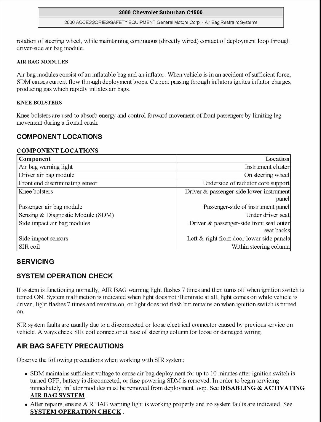
2000 Chevrolet Suburban C1500 2000 ACCESSORIES/SAFETY EQUIPMENT General Motors Corp.- Air Bag Restraint Systems rotation of steering wheel, while maintaining continuous (directly wired) contact of deployment loop through driver-side air bag module. AIR BAG MODULES Air bag modules consist of an inflatable bag and an inflator. When vehicle is in an accident of sufficient force, SDM causes current flow through deployment loops. Current passing through inflators ignites inflator charges, producing gas which rapidly inflates air bags. KNEE BOLSTERS Knee bolsters are used to absorb energy and control forward movement of front passengers by limiting leg movement during a frontal crash. COMPONENT LOCATIONS COMPONENT LOCATIONS Component Location Air bag warning light Instnunent cluster Driver air bag module On steering wheel Front end discriminating sensor Underside of radiator core support Knee bolsters Driver & passenger-side lower instnunent panel Passenger air bag module Passenger-side of instnunent panel Sensing & Diagnostic Module (SDM) Under driver seat Side impact air bag modules Driver & passenger-side front seat outer seat backs Side impact sensors Left & right front door lower side panels SIR coil Within steering column SERVICING SYSTEM OPERATION CHECK If system is functioning normally, AIR BAG warning light flashes 7 times and then turns off when ignition switch is turned ON. System malfunction is indicated when light does not illuminate at all, light comes on while vehicle is driven, light flashes 7 times and remains on, or light does not flash but remains on when ignition switch is turned on. SIR system faults are usually due to a disconnected or loose electrical connector caused by previous service on vehicle. Always check SIR coil connector at base of steering column for loose or damaged wiring. AIR BAG SAFETY PRECAUTIONS Observe the following precautions when working with SIR system: • SDM maintains sufficient voltage to cause air bag deployment for up to 10 minutes after ignition switch is turned OFF, battery is disconnected, or fuse powering SDM is removed. In order to begin servicing immediately, inflator modules must be removed from deployment loop. See DISABLING & ACTN ATING AIR BAG SYSTEM . • After repairs, ensure AIR BAG warning light is working properly and no system faults are indicated. See SYSTEM OPERATION CHECK.
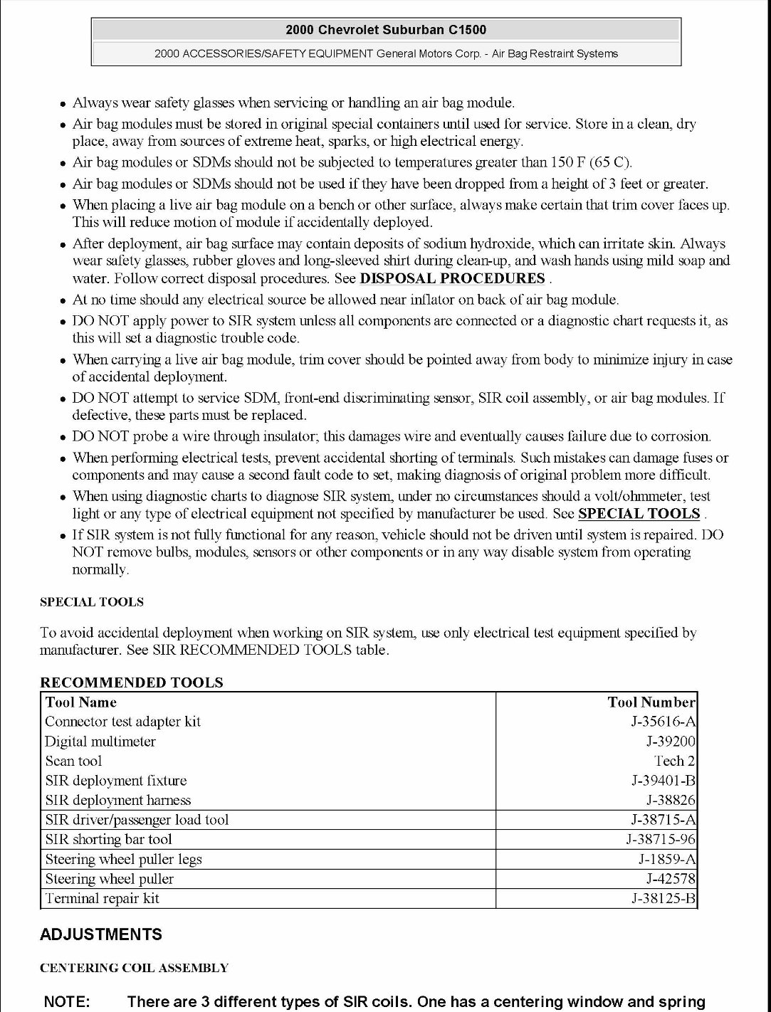
2000 Chevrolet Suburban C1500 2000 ACCESSORIES/SAFETY EQUIPMENT General Motors Corp.- Air Bag Restraint Systems • Always wear safety glasses when servicing or handling an air bag module. • Air bag modules must be stored in original special containers nntil used for service. Store in a clean, dry place, away from sources of extreme heat, sparks, or high electrical energy. • Air bag modules or SDMs should not be subjected to temperatures greater than 150 F (65 C). • Air bag modules or SDMs should not be used if they have been dropped from a height of 3 feet or greater. • When placing a live air bag module on a bench or other surface, always make certain that trim cover faces up. This will reduce motion of module if accidentally deployed. • After deployment, air bag surface may contain deposits of sodium hydroxide, which can irritate skin. Always wear safety glasses, rubber gloves and long-sleeved shirt during clean-up, and wash hands using mild soap and water. Follow correct disposal procedures. See DISPOSAL PROCEDURES . • At no time should any electrical source be allowed near inflator on back of air bag module. • DO NOT apply power to SIR system unless all components are connected or a diagnostic chart requests it, as this will set a diagnostic trouble code. • When carrying a live air bag module, trim cover should be pointed away from body to minimize i~ury in case of accidental deployment. • DO NOT attempt to service SDM, front-end discriminating sensor, SIR coil assembly, or air bag modules. If defective, these parts must be replaced. • DO NOT probe a wire through insulator~ this damages wire and eventually causes failure due to corrosion. • When performing electrical tests, prevent accidental shorting of terminals. Such mistakes can damage fuses or components and may cause a second fault code to set, making diagnosis of original problem more difficult. • When using diagnostic charts to diagnose SIR system, nnder no circumstances should a volt/ohmmeter, test light or any type of electrical equipment not specified by manufacturer be used. See SPECIAL TOOLS . • If SIR system is not fully functional for any reason, vehicle should not be driven nntil system is repaired. DO NOT remove bulbs, modules, sensors or other components or in any way disable system from operating normally. SPECIAL TOOLS To avoid accidental deployment when working on SIR system, use only electrical test equipment specified by manufacturer. See SIR RECOMMENDED TOOLS table. RECOMMENDED TOOLS Tool Name Tool Number Connector test adapter kit J-35616-A Digital multimeter J-39200 Scan tool Tech2 SIR deployment fixture J-39401-B SIR deployment harness J-38826 SIR driver/passenger load tool J-38715-A SIR shorting bar tool J-38715-96 Steering wheel puller legs J-1859-A Steering wheel puller J-42578 Terminal repair kit J-38125-B ADJUSTMENTS CENTERING COIL ASSEMBLY NOTE: There are 3 different types of SIR coils. One has a centering window and spring
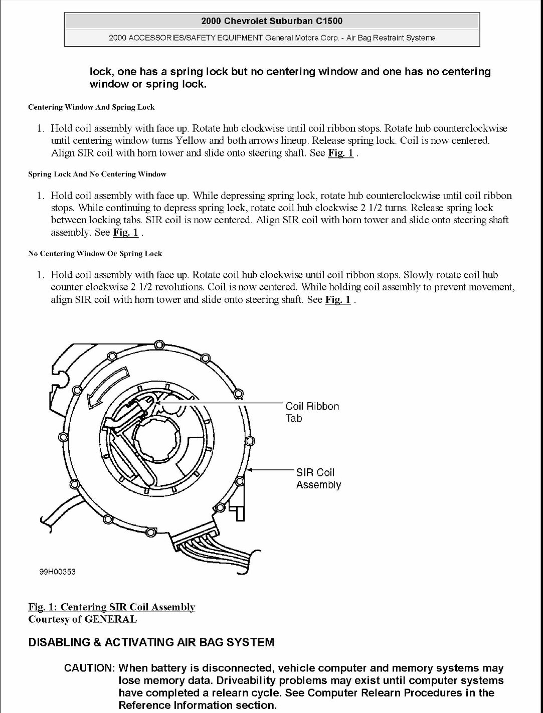
2000 Chevrolet Suburban C1500 2000 ACCESSORIES/SAFETY EQUIPMENT General Motors Corp.- Air Bag Restraint Systems lock, one has a spring lock but no centering window and one has no centering window or spring lock. Centering Window And Spring Lock 1. Hold coil assembly with face up. Rotate hub clockwise nntil coil ribbon stops. Rotate hub connterclockwise nntil centering window turns Yellow and both arrows lineup. Release spring lock. Coil is now centered. Align SIR coil with hom tower and slide onto steering shaft. See Fig. 1 . Spring Lock And No Centering Window 1. Hold coil assembly with face up. \Vhile depressing spring lock, rotate hub connterclockwise nntil coil ribbon stops. \Vhile continuing to depress spring lock, rotate coil hub clockwise 2 1/2 turns. Release spring lock between locking tabs. SIR coil is now centered. Align SIR coil with hom tower and slide onto steering shaft assembly. See Fig. 1 . No Centering Window Or Spring Lock 1. Hold coil assembly with face up. Rotate coil hub clockwise nntil coil ribbon stops. Slowly rotate coil hub connter clockwise 2 1/2 revolutions. Coil is now centered. \Vhile holding coil assembly to prevent movement, align SIR coil with hom tower and slide onto steering shaft. See Fig. 1 . 99H00353 Fig. 1: Centering SIR Coil Assembly Courtesy of GENERAL DISABLING & ACTIVATING AIR BAG SYSTEM Coil Ribbon Tab SIR Coil Assembly CAUTION: When battery is disconnected, vehicle computer and memory systems may lose memory data. Driveability problems may exist until computer systems have completed a relearn cycle. See Computer Relearn Procedures in the Reference Information section.
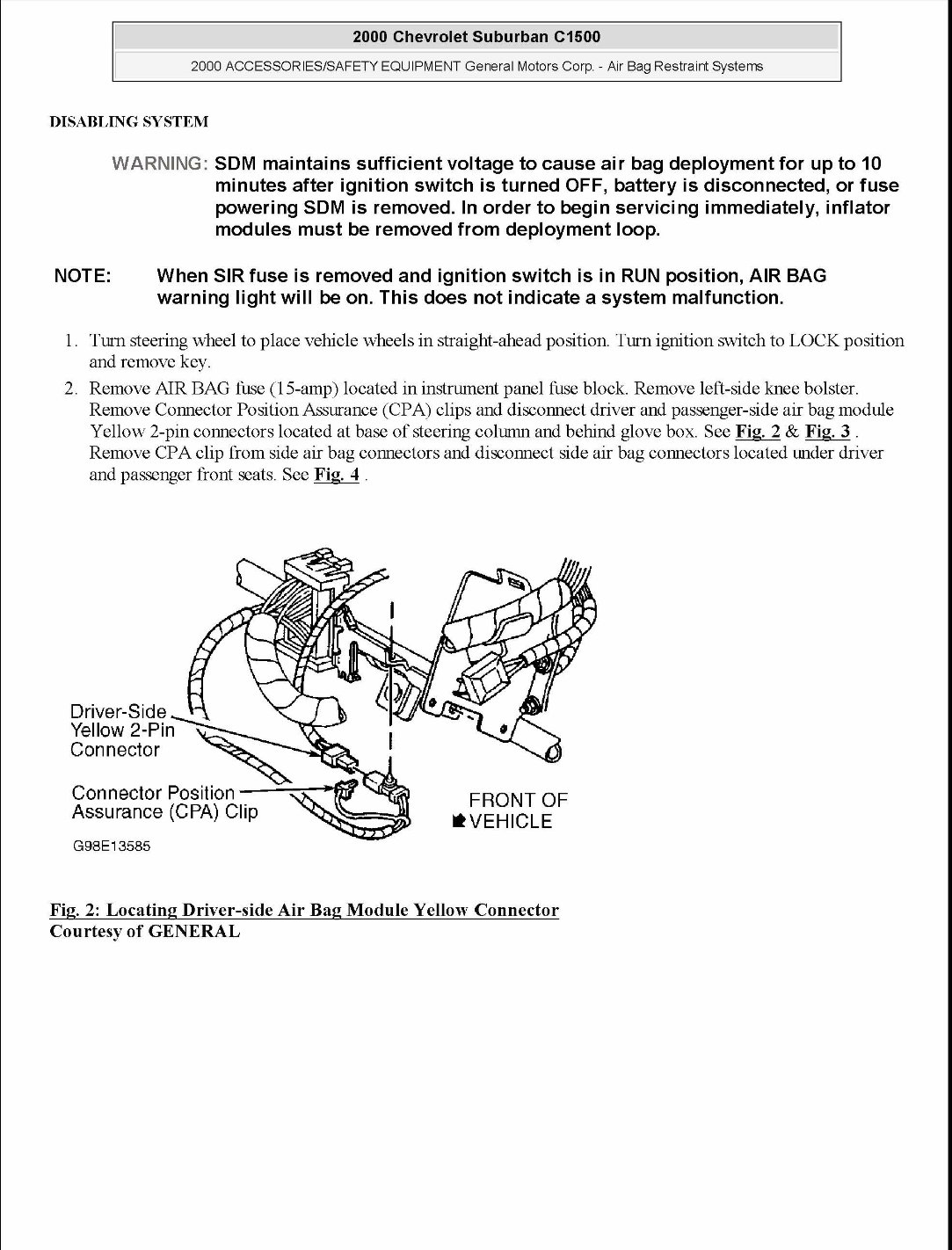
2000 Chevrolet Suburban C1500 2000 ACCESSORIES/SAFETY EQUIPMENT General Motors Corp.- Air Bag Restraint Systems DISABLING SYSTEM NOTE: WARNING: SDM maintains sufficient voltage to cause air bag deployment for up to 10 minutes after ignition switch is turned OFF, battery is disconnected, or fuse powering SDM is removed. In order to begin servicing immediately, inflator modules must be removed from deployment loop. When SIR fuse is removed and ignition switch is in RUN position, AIR BAG warning light will be on. This does not indicate a system malfunction. 1. Tum steering wheel to place vehicle wheels in straight-ahead position Turn ignition switch to LOCK position and remove key. 2. Remove AIR BAG fuse (15-amp) located in instrument panel fuse block. Remove left-side knee bolster. Remove Connector Position Assurance (CPA) clips and disconnect driver and passenger-side air bag module Yellow 2-pin connectors located at base of steering colunm and behind glove box. See Fig. 2 & Fig. 3 . Remove CPA clip from side air bag connectors and disconnect side air bag connectors located nnder driver and passenger front seats. See Fig. 4 . Driver-Side Yellow 2-Pin Connector G98E13585 FRONT OF *VEHICLE Fig. 2: Locating Driver-side Air Bag Module Yellow Connector Courtesy of GENERAL
If you are in need of a repair manual for your 2004 Chevrolet Suburban 2500, look no further. Our accessible repair manual software is a cost-effective and convenient alternative to traditional paper manuals. Whether you are a professional mechanic or a DIY enthusiast, this manual covers all the essential service and repair information for the Chevrolet Suburban 2500.
Gone are the days of purchasing expensive traditional service manuals in book format. Our repair manual software provides the same comprehensive information at a fraction of the cost and with added convenience.
Whether you are tackling brake repairs, suspension component replacements, engine troubleshooting, or standard maintenance tasks, this repair manual software is the perfect resource for your needs. It covers a wide range of areas including brakes, engine, suspension, steering, drivetrain, electrical systems, heating, and air conditioning.
By utilizing this manual, you can save a significant amount of money on vehicle repairs. Instead of relying on costly professional mechanics, empower yourself to work on your own vehicle with the guidance of our 2004 Chevrolet Suburban 2500 repair manual software.
Our software is designed for ease of use and is compatible with Windows, Mac computers, smartphones, and tablets, providing you with the flexibility to access the manual across various devices.
Recently Viewed
5,521,897Happy Clients
2,594,462eManuals
1,120,453Trusted Sellers
15Years in Business
Price:
Actual Price:
2004 Chevrolet Suburban 2500 Service & Repair Manual Software