2007-2013 Chevrolet Silverado 3500 HD Service & Repair Manual
What's Included?
Lifetime Access
Fast Download Speeds
Online & Offline Access
Access PDF Contents & Bookmarks
Full Search Facility
Print one or all pages of your manual
2007-2013 CHEVROLET SILVERADO 3500HD SERVICE AND REPAIR MANUAL
2011 ACCESSORIES AND EQUIPMENT Adjustable Pedals - Sierra And Silverado SPECIFICATIONS FASTENER TIGHTENING SPECIFICATIONS WIRING SCHEMATICS ADJUSTABLE PEDAL WIRING SCHEMATICS Application Specification Metric English Accelerator Actuator Screws 2.5 N.m 22 lb in Accelerator Pedal Bracket Nuts 9 N.m 80 lb in Adjustable Pedal Bracket Nuts 36 N.m 27 lb ft Adjustable Pedal Bracket to Dash Panel Bolt 36 N.m 27 lb ft Brake and Accelerator Pedal Position Sensor Bolts 2 N.m 18 lb in Brake Pedal Pushrod Retainer Bolt 10 N.m 89 lb in Master Cylinder Nuts - With JL4 32 N.m 24 lb ft Master Cylinder Nuts - Without JL4 25 N.m 18 lb ft Transmission Range Selector Cable Support Bolt 10 N.m 89 lb in 2011 Chevrolet Silverado 3500 HD 2011 ACCESSORIES AND EQUIPMENT Adjustable Pedals - Sierra And Silverado
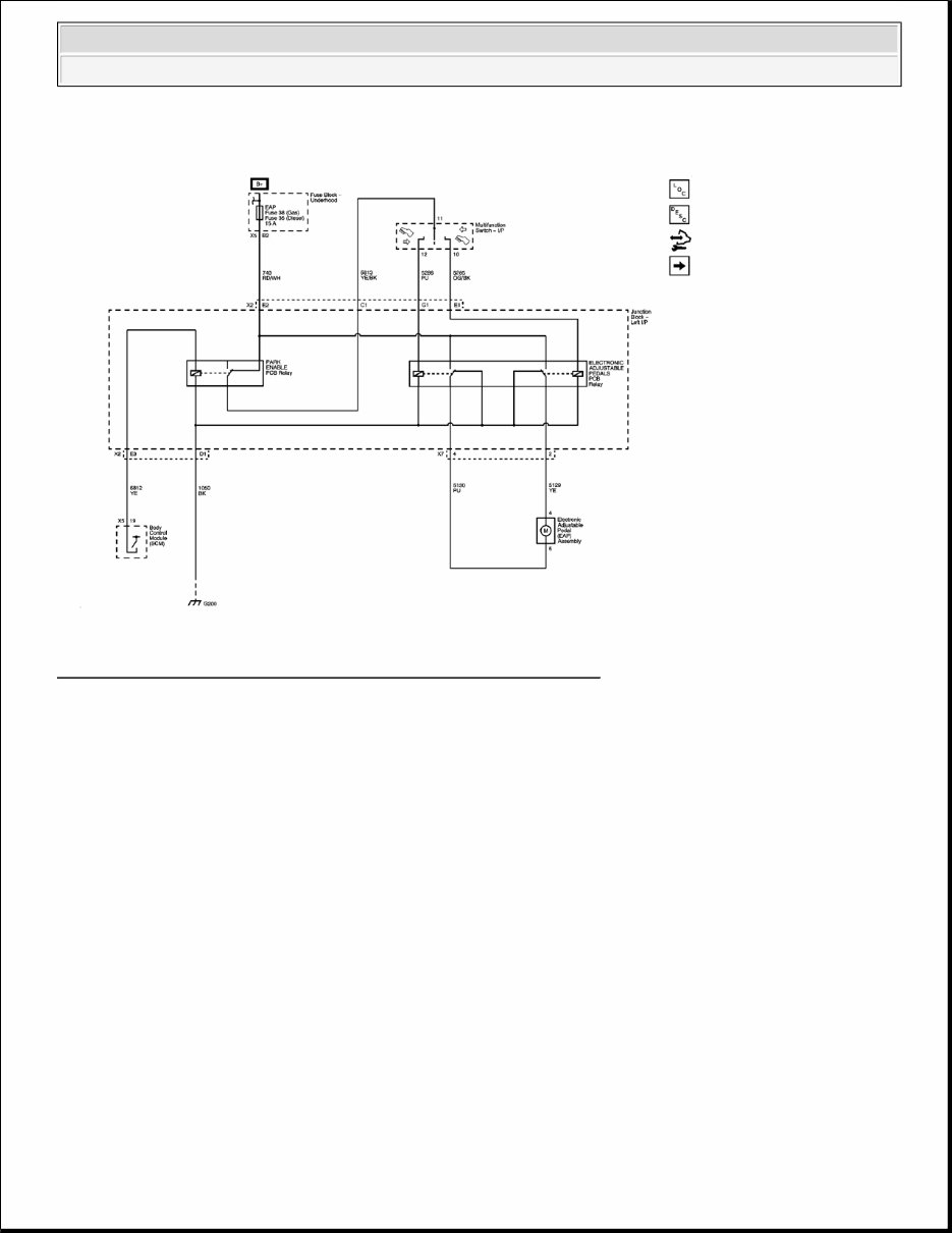
Fig. 1: Adjustable Pedal Wiring Schematic (Without Memory Seats) Courtesy of GENERAL MOTORS CORP. 2011 Chevrolet Silverado 3500 HD 2011 ACCESSORIES AND EQUIPMENT Adjustable Pedals - Sierra And Silverado
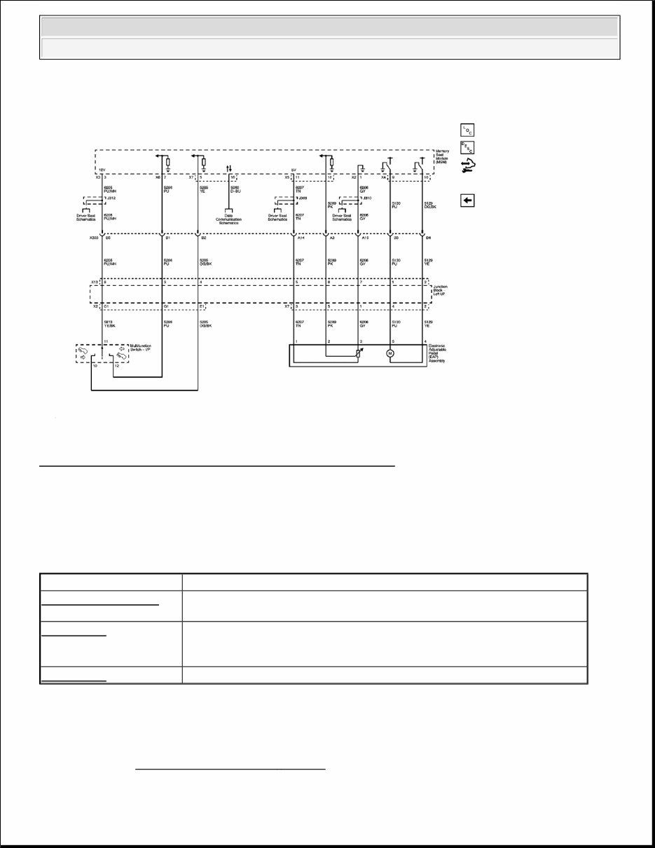
Fig. 2: Adjustable Pedal Wiring Schematic (With Memory Seats) Courtesy of GENERAL MOTORS CORP. DIAGNOSTIC INFORMATION AND PROCEDURES DIAGNOSTIC CODE INDEX DIAGNOSTIC CODE INDEX DTC B3604 OR B3605 Diagnostic Instructions Perform the Diagnostic System Check - Vehicle prior to using this diagnostic procedure. DTC Description DTC B3604 or B3605 B3604 01: Adjustable Foot Pedal Forward Switch Circuit Short to Battery B3605 01: Adjustable Foot Pedal Rearward Switch Circuit Short to Battery DTC B3606 B3606 01: Adjustable Foot Pedal Position Sensor Circuit Short to Battery B3606 06: Adjustable Foot Pedal Position Sensor Circuit Short to Ground or Open DTC B3631 B3631 00: Adjustable Foot Pedal Inhibit Circuit 2011 Chevrolet Silverado 3500 HD 2011 ACCESSORIES AND EQUIPMENT Adjustable Pedals - Sierra And Silverado
Review Strategy Based Diagnosis for an overview of the diagnostic approach. Diagnostic Procedure Instructions provides an overview of each diagnostic category. DTC Descriptors DTC B3604 01 Adjustable Foot Pedal Forward Switch Circuit Short to Battery DTC B3605 01 Adjustable Foot Pedal Rearward Switch Circuit Short to Battery Diagnostic Fault Information Circuit/System Description The adjustable pedals forward and rearward switches are inputs to the memory seat module (MSM). The MSM supplies the switch assembly with a battery positive reference voltage. When the switch is operated to the forward or rearward direction, battery positive voltage is applied to the forward or rearward switch signal inputs. Conditions for Running the DTC System voltage is 9-16 volts. Conditions for Setting the DTC The forward and rearward switch signal circuits are active at the same time. Action Taken When the DTC Sets The adjustable pedals will be disabled. Conditions for Clearing the DTC Circuit Short to Ground Open/High Resistance Short to Voltage Signal Performance Switch Reference Voltage 1 1 - - Forward Switch Signal 2 2 B3604 01 - Rearward Switch Signal 3 3 B3605 01 - 1. Adjustable Pedals Inoperative 2. Adjustable Pedals Forward Inoperative 3. Adjustable Pedals Rearward Inoperative 2011 Chevrolet Silverado 3500 HD 2011 ACCESSORIES AND EQUIPMENT Adjustable Pedals - Sierra And Silverado
The DTC becomes history when the conditions for setting the DTC are no longer present. The history DTC clears after 100 malfunction-free ignition cycles. Reference Information Schematic Reference Adjustable Pedal Schematics Connector End View Reference COMPONENT CONNECTOR END VIEWS - INDEX Description and Operation Adjustable Pedals Description and Operation (with Memory) or Adjustable Pedals Description and Operation (w/o Memory) Electrical Information Reference Circuit Testing Connector Repairs Testing for Intermittent Conditions and Poor Connections Wiring Repairs Scan Tool Reference Control Module References for scan tool information Circuit/System Verification Ignition ON, observe the scan tool Pedal Forward Switch and Pedal Aft Switch parameters while cycling the adjustable pedal switch between the FWD and RWD position. The appropriate parameter should change between Active and Inactive as commanded. Circuit/System Testing 1. Disconnect the harness connector at the adjustable pedal switch. 2. Ignition ON, test for 11.8-12.2 volts between the appropriate 12-volt reference circuit listed below and ground: X88/Z88 - terminal 11 Z75 - terminal 5 If greater than the specified range, test the 12-volt reference circuit for a short to voltage. If the circuit tests normal, replace the MSM. 2011 Chevrolet Silverado 3500 HD 2011 ACCESSORIES AND EQUIPMENT Adjustable Pedals - Sierra And Silverado
If less than the specified range, test the 12-volt reference circuit for a short to ground or an open/high resistance. If the circuit tests normal, replace the MSM. 3. Verify the scan tool Pedal Forward Switch parameter is Inactive. If not the specified value, test the appropriate signal circuit terminal listed below for a short to voltage. If the circuit tests normal, replace the MSM. X88/Z88 - terminal 12 Z75 - terminal 6 4. Verify the scan tool Pedal Aft Switch parameter is Inactive. If not the specified value, test the appropriate signal circuit terminal listed below for a short to voltage. If the circuit tests normal, replace the MSM. X88/Z88 - terminal 10 Z75 - terminal 4 5. Install a 3A fused jumper wire between the appropriate signal circuit terminal listed below and B+. The scan tool Pedal Forward Switch parameter should be Active. X88/Z88 - terminal 12 Z75 - terminal 6 If not the specified value, test the signal circuit for a short to ground or an open/high resistance. If the circuit tests normal, replace the MSM. 6. Install a 3A fused jumper wire between the appropriate signal circuit terminal listed below and B+. The scan tool Pedal Aft Switch parameter should be Active. X88/Z88 - terminal 10 Z75 - terminal 4 If not the specified value, test the signal circuit for a short to ground or an open/high resistance. If the circuit tests normal, replace the MSM. 7. If all circuits test normal, test or replace the adjustable pedal switch. Component Testing X88/Z88 1. Ignition OFF, disconnect the harness connector at the adjustable pedal switch. 2. Test for infinite resistance between the 12-volt reference terminal 11 and the signal terminals listed below: Terminal 10 Terminal 12 If not the specified value, replace the adjustable pedal switch. 3. Adjustable pedal switch in the FWD position, test for less than 2 ohms between the 12-volt reference terminal 11 and the signal terminal 12. If greater than the specified range, replace the adjustable pedal switch. 4. Adjustable pedal switch in the RWD position, test for less than 2 ohms between the 12-volt reference terminal 11 and the signal terminal 10. 2011 Chevrolet Silverado 3500 HD 2011 ACCESSORIES AND EQUIPMENT Adjustable Pedals - Sierra And Silverado
If greater than the specified range, replace the adjustable pedal switch. Z75 1. Ignition OFF, disconnect the harness connector at the adjustable pedal switch. 2. Test for infinite resistance between the 12-volt reference terminal 5 and the signal terminals listed below: Terminal 4 Terminal 6 If not the specified value, replace the adjustable pedal switch. 3. Adjustable pedal switch in the FWD position, test for less than 2 ohms between the 12-volt reference terminal 5 and the signal terminal 6. If greater than the specified range, replace the adjustable pedal switch. 4. Adjustable pedal switch in the RWD position, test for less than 2 ohms between the 12-volt reference terminal 5 and the signal terminal 4. If greater than the specified range, replace the adjustable pedal switch. Repair Procedures Perform the Diagnostic Repair Verification after completing the diagnostic procedure. Accessory Switch Replacement (without RPO SLT) or Accessory Switch Replacement (with RPO SLT) Control Module References for the MSM replacement, setup, and programming DTC B3606 Diagnostic Instructions Perform the Diagnostic System Check - Vehicle prior to using this diagnostic procedure. Review Strategy Based Diagnosis for an overview of the diagnostic approach. Diagnostic Procedure Instructions provides an overview of each diagnostic category. DTC Descriptors DTC B3606 01 Adjustable Foot Pedal Position Sensor Circuit Short to Battery DTC B3606 06 Adjustable Foot Pedal Position Sensor Circuit Short to Ground or Open Diagnostic Fault Information 2011 Chevrolet Silverado 3500 HD 2011 ACCESSORIES AND EQUIPMENT Adjustable Pedals - Sierra And Silverado
Circuit/System Description The memory seat module (MSM) monitors the location of the adjustable pedals using the adjustable pedals position sensor. The adjustable pedals position sensor is supplied with 5-volt reference and ground circuits from the MSM. The position sensor signal circuit is referenced from ground within the MSM. The signal voltage monitored by the MSM ranges from 0.45-4.55 volts. Conditions for Running the DTC System voltage to the MSM must be 9-16 volts. Conditions for Setting the DTC The position sensor input to the MSM is not within the 0.45-4.55 volt range. Action Taken When the DTC Sets Memory recall functions will be suspended. Conditions for Clearing the DTC The DTC becomes history when the conditions for setting the DTC are no longer present. The history DTC clears after 100 malfunction-free ignition cycles. Reference Information Schematic Reference Adjustable Pedal Schematics Connector End View Reference COMPONENT CONNECTOR END VIEWS - INDEX Description and Operation Adjustable Pedals Description and Operation (with Memory) or Adjustable Pedals Description and Operation (w/o Memory) Electrical Information Reference Circuit Short to Ground Open/High Resistance Short to Voltage Signal Performance 5-Volt Reference B3606 06 B3606 06 B3601 01 - Signal B3606 06 B3606 06 B3601 01 - Low Reference - B3606 06 - - 2011 Chevrolet Silverado 3500 HD 2011 ACCESSORIES AND EQUIPMENT Adjustable Pedals - Sierra And Silverado
Circuit Testing Connector Repairs Testing for Intermittent Conditions and Poor Connections Wiring Repairs Scan Tool Reference Control Module References for scan tool information Circuit/System Testing 1. Ignition OFF, disconnect the harness connector at the adjustable pedal motor. 2. Ignition OFF, test for less than 10 ohm between the low reference circuit terminal 3 and ground. If greater than the specified range, test the low reference circuit for an open/high resistance. If the circuit tests normal, replace the MSM. 3. Ignition ON, test for 4.8-5.2 volts between the 5-volt reference circuit terminal 1 and ground. If less than the specified range, test the 5-volt reference circuit for a short to ground or an open/high resistance. If the circuit tests normal, replace the MSM. If greater than the specified range, test the 5-volt reference circuit for a short to voltage. If the circuit tests normal, replace the MSM. 4. Verify the scan tool Pedal Position parameter is less than 0.45 volt. If greater than the specified range, test the signal circuit terminal 2 for a short to voltage. If the circuit tests normal, replace the MSM. 5. Install a 3A fused jumper wire between the signal circuit terminal 2 and the 5-volt reference circuit terminal 1. Verify the scan tool Pedal Position parameter is greater than 4.55 volts. If less than the specified range, test the signal circuit for short to ground or an open/high resistance. If the circuit tests normal, replace the MSM. 6. If all circuits test normal, test or replace the adjustable pedal motor. Repair Procedures Perform the Diagnostic Repair Verification after completing the diagnostic procedure. Brake Pedal Assembly Replacement Control Module References for the MSM replacement, setup, and programming DTC B3631 Diagnostic Instructions Perform the Diagnostic System Check - Vehicle prior to using this diagnostic procedure. Review Strategy Based Diagnosis for an overview of the diagnostic approach. Diagnostic Procedure Instructions provides an overview of each diagnostic category. 2011 Chevrolet Silverado 3500 HD 2011 ACCESSORIES AND EQUIPMENT Adjustable Pedals - Sierra And Silverado
2007-2013 Chevrolet Silverado 3500 HD Service & Repair Manual
Engines covered:
6.0L Vortec 6000 V8
6.6L Duramax V8 (diesel)
Transmissions covered:
Allison 1000 6-speed automatic
Hydra-Matic 6L90 6-speed automatic
4L80-E 4-speed automatic
The 2007-2013 Chevrolet Silverado 3500 HD Service & Repair Manual lays out the factory-approved procedures for keeping one of GM’s heaviest workhorses in top shape. Covering both the 6.0L Vortec and 6.6L Duramax engines, it provides detailed steps for everything from routine maintenance to full overhauls, making it useful whether you’re a pro mechanic in the bay or a DIYer in the garage.
Inside, you’ll find complete transmission coverage, including the Allison 1000, Hydra-Matic 6L90, and 4L80-E units, along with servicing instructions for transfer cases and driveline components. Suspension, steering, and braking systems are broken down with specifications, adjustments, and clear servicing procedures. Troubleshooting sections walk through common mechanical and hydraulic issues, giving you the right path to follow.
Content overview:
Full engine repair procedures for 6.0L and 6.6L Duramax diesel engines
Automatic transmission service for 4L60-E and 6L90 units
Suspension repair procedures for front, rear, and general chassis components
Braking system guides for disc, drum, anti-lock, and hydraulic brake systems
Detailed wiring diagrams and component locator maps for all electrical systems
HVAC repair for both automatic and manual climate control setups
Transfer case service for BW 4485-NR3, MP 1222/1225/1226 NQG, 1625/1626 NQF, and 3023/3024 NQH models
Full coverage of steering, power steering, and column assembly repairs
Frame, underbody, bumpers, and body panel replacement procedures
Interior repair for seats, trim, instrument panels, and console systems
Service data for cruise control, lighting, wipers, horn, and sunroof
Programming instructions and module setup for electronic components
Diagnostic connector locations, DTC index, and troubleshooting guidance
Keyless entry, theft deterrent, immobilizer, and object detection systems
Detailed instructions for cooling system, exhaust, and propeller shaft service
Coverage of drivetrain: front/rear axles, driveshafts, and PTO units
Factory torque specs, maintenance intervals, and fluid capacity charts
The manual also includes in-depth guidance for HVAC systems, body repairs, and interior components, plus factory service specs like torque values, fluid capacities, and inspection intervals. It’s a thorough, no-nonsense reference designed to keep Silverado 3500 HD models running strong.
Printable: Yes Language: English Compatibility: Pretty much any electronic device, incl. PC & Mac computers, Android and Apple smartphones & tablet, etc. Requirements: Adobe Reader (free)
Recently Viewed
5,521,897Happy Clients
2,594,462eManuals
1,120,453Trusted Sellers
15Years in Business
Price:
Actual Price:
2007-2013 Chevrolet Silverado 3500 HD Service & Repair Manual