2001-2005 Chevrolet Silverado 1500 Service & Repair Manual
What's Included?
Lifetime Access
Fast Download Speeds
Online & Offline Access
Access PDF Contents & Bookmarks
Full Search Facility
Print one or all pages of your manual
2001 ACCESSORIES & EQUIPMENT Anti-Theft Systems - Sierra, Silverado, Suburban, Tahoe, Yukon & Yukon XL DESCRIPTION CONTENT THEFT DETERRENT SYSTEM The Content Theft Deterrent (CTD) anti-theft system is designed to deter vehicle theft by pulsing horns and exterior lights when unauthorized vehicle entry or tampering is detected. The CTD system operates separately from Passlock(tm) system. System components include door jamb switches, liftgate jamb switches, shock sensor, exterior lights, SECURITY indicator light, horn relay, headlight control module and Body Control Module (BCM). PASSLOCK(TM) SYSTEM The Passlock(tm) system is designed to prevent vehicle theft by disabling the engine unless a mechanical key is used to correctly engage and rotate the Passlock(tm) lock cylinder. System components include ignition switch, Passlock(tm) lock cylinder, Passlock(tm) sensor, Passlock(tm) module and Powertrain Control Module (PCM) or Vehicle Control Module (VCM). OPERATION CONTENT THEFT DETERRENT SYSTEM BCM controls CTD system operation. System has the following modes: z Off When ignition switch is in RUN position and doors are closed. SECURITY indicator light will stay off. z Idle When ignition switch is in RUN position and any door is open. SECURITY indicator light will stay off. z Disarmed When ignition switch is in LOCK position and doors are closed. SECURITY indicator light will stay off. z Ready To Arm WARNING: Vehicles are equipped with air bag supplemental restraint system. Before attempting ANY repairs involving steering column, instrument panel or related components, see SERVICE PRECAUTIONS and DISABLING & ACTIVATING AIR BAG SYSTEM in appropriate AIR BAG RESTRAINT SYSTEMS article.
When ignition switch is in LOCK position and any door is opened. SECURITY indicator light will flash. z Arm Initiated When ignition switch is in LOCK position, any door is opened and BCM detects a LOCK command from power door lock switch or Remote Keyless Entry (RKE) transmitter. SECURITY indicator light will stay on. z Arm Delay When vehicle is in arm initiated mode and all doors are closed, system will enter arm delay mode for 15 seconds. SECURITY indicator light will stay on. z Armed After 15 seconds in arm delay mode without any doors opening, CTD enters armed mode. BCM monitors inputs to determine whether to enter alarm or disarm mode. SECURITY indicator light will stay off. z Alarm If BCM receives an open door input, horns and lights will alternate on and off for two minutes, unless BCM receives an unlock command. If two minutes elapses, CTD system will return to armed mode. If PCM/VCM receives a valid Passlock(tm) ignition key rotation while in alarm mode, CTD system will return to off mode. z Remote Panic Alarm/Vehicle Locator When PANIC button on Remote Keyless Entry (RKE) transmitter is pressed, horns and lights will alternate on and off for 30 seconds, unless PANIC button on RKE is pressed again. PASSLOCK(TM) SYSTEM When mechanical key turns Passlock(tm) lock cylinder, a Resistance Code (R-Code) is created by a rotating magnet turning past a stationary Hall Effect sensor. R-Code is sent to the Passlock(tm) module. The module determines validity of R-Code within a preset time window, then sends a coded password to Powertrain Control Module (PCM) or Vehicle Control Module (VCM), which then allows fuel injectors to operate normally. If Passlock(tm) module receives the incorrect R-Code, PCM/VCM will enter long tamper mode. During long tamper mode, fuel injectors are shut off for 10 minutes and SECURITY indicator light will flash. Vehicle may crank and temporarily start during long tamper mode, but will soon stall due to fuel shut-off. If coded password is not received or is incorrect by the time engine starts, PCM/VCM will enter lock-out mode. If a large magnet is placed near Passlock(tm) sensor or a tamper (wrong key) exists, PCM/VCM will enter lock-out mode. Lack of data from Passlock(tm) sensor to Passlock(tm) module will set Diagnostic Trouble Codes (DTC) and illuminate SECURITY indicator light. COMPONENT LOCATIONS
COMPONENT LOCATIONS PROGRAMMING PASSLOCK(TM) SYSTEM AUTO LEARN 1. Clear all DTCs. Turn ignition off. Replace component(s) as necessary. 2. With transmission in Park (A/T) or Neutral (M/T), momentarily turn ignition switch to START position (engine will not start). Leave ignition switch in RUN position (engine off). If Passlock(tm) sensor was replaced, SECURITY indicator light will flash for 10 minutes. If Passlock(tm) module was replaced, SECURITY indicator light will flash for a few seconds, and then remain on for 10 minutes. If PCM/VCM was replaced with a new PCM/VCM, vehicle may start and procedure may not be needed. If replacement PCM/VCM was used even momentarily, SECURITY indicator light will flash for a few seconds, and then remain on for 10 minutes. After 10 minutes, when light turns off, turn ignition switch to OFF position for 5 seconds. 3. Repeat step 2 twice more. Ignition switch must be turned to OFF position. Auto learn procedure will be completed during next start attempt. Clear all DTCs. If PCM/VCM was replaced, reprogram PCM/VCM. See appropriate SELF-DIAGNOSTICS article in ENGINE PERFORMANCE. TROUBLE SHOOTING PRELIMINARY INSPECTION 1. Check all fuses. Ensure all connectors in system are mated correctly. Using a scan tool, check for engine performance-related DTCs. See appropriate SELF-DIAGNOSTICS article in ENGINE PERFORMANCE. 2. Check for broken or partially broken wires. Check for correct installation of aftermarket electronic equipment. Ensure all grounds are clean and tight. CONTENT THEFT DETERRENT SYSTEM OPERATION CHECK 1. Close all vehicle doors. Turn ignition on. SECURITY indicator light should stay off. 2. Open driver's window. Turn ignition off. Remove key from ignition. Open driver's door. SECURITY indicator light should flash. 3. Press LOCK button on Remote Keyless Entry (RKE) transmitter. SECURITY indicator light should stay on. Component Location Body Control Module Lower Left Side Of Instrument Panel, Under Steering Column Passlock(tm) Sensor Part Of Ignition Lock Cylinder Powertrain Control Module In Left Front Of Engine Compartment NOTE: This procedure allows relearning of Passlock(tm) module or PCM/VCM learned data code after replacement of Passlock(tm) module, Passlock(tm) sensor or PCM/VCM. DTC B3031 will set when entering programming mode.
4. Close all doors. SECURITY indicator light should turn off after 15 seconds. System is now armed. 5. Activate alarm by performing the following: z Reach in window and unlock door using power door lock switch. Open door. z Reach in window and unlock door using lock lever. Open door. The horn should sound and exterior lights should flash. If alarm does not operate, perform BCM diagnostic system check. See appropriate BODY CONTROL MODULES article. If horn does not operate as specified, diagnose and repair horn system as necessary. See appropriate STEERING COLUMN SWITCHES article. If exterior lights do not operate as specified, diagnose and repair exterior light circuits as necessary. See EXTERIOR LIGHTS article. 6. Using key, unlock door. Alarm should disarm. If alarm does not disarm, see TEST 1: CTD SYSTEM DOES NOT DISARM WITH KEY LOCK under SYMPTOM TESTS. 7. Reset alarm. Activate alarm. Press UNLOCK button on RKE transmitter. Alarm should disarm. If alarm does not disarm, perform BCM diagnostic system check. See appropriate BODY CONTROL MODULES article. SELF-DIAGNOSTIC SYSTEM DIAGNOSTIC SYSTEM CHECK 1. Connect scan tool. Turn ignition switch to RUN position, engine off. Attempt to communicate with BCM and Instrument Panel Cluster (IPC). If scan tool communicates with BCM and IPC, go to next step. If scan tool does not communicate with BCM and IPC, diagnose and repair communication problem. See appropriate BODY CONTROL MODULES article. 2. Check BCM for DTCs. If no DTCs exist, go to next step. If DTCs exist, go to step 4 . 3. Momentarily turn ignition switch to START position, do not start engine. Release ignition switch to RUN position. With scan tool, observe Passlock(tm) code in BCM data list. If Passlock(tm) code indicates OPEN, see DTC B2958: PASSLOCK(tm) SENSOR DATA CIRCUIT HIGH under DIAGNOSTIC TESTS. If Passlock(tm) code does not indicate OPEN, see SYMPTOM INDEX table under SYMPTOM TESTS. CAUTION: Do not replace Passlock(tm) module unless there are no PCM/VCM DTCs and a current Passlock(tm) module DTC exists after system check and DTC test has been completed. Do not replace Passlock(tm) module based on history DTCs. CAUTION: Always remove Brown connector first and install Brown connector last on BCM. NOTE: System tests are written specifically for General Motor's Tech 2 scan tool. A generic scan tool may not be capable of performing all necessary test functions.
4. If scan tool displays any DTCs beginning with "U", diagnose and repair DTCs as necessary. See appropriate BODY CONTROL MODULES article. If scan tool does not display any DTCs beginning with "U", go to next step. 5. If scan tool displays DTC B1000, see appropriate BODY CONTRLS MODULE article. If other DTCs are displayed, perfrom appropriate test. See DIAGNOSTIC TROUBLE CODE INDEX DIAGNOSTIC TROUBLE CODE INDEX DIAGNOSTIC TESTS DTC B2947: PASSLOCK(TM) SENSOR POWER CIRCUIT LOW Circuit Description This DTC sets when Passlock(tm) power is active and Passlock(tm) power is not present for .5 second. If ignition was off, vehicle will not start. If vehicle was running, vehicle will restart, but SECURITY indicator light will remain illuminated. Diagnostic Procedure 1. If diagnostic system check has been performed, go to next step. If diagnostic system check has not been performed, see DIAGNOSTIC SYSTEM CHECK under SELF-DIAGNOSTIC SYSTEM. 2. Connect scan tool. Turn ignition switch to RUN position, engine off. Using scan tool, check for BCM DTC (1) Description B2947 Passlock(tm) Sensor Power Circuit Low B2948 Passlock(tm) Sensor Power Circuit High B2957 Passlock(tm) Sensor Data Circuit Low B2958 Passlock(tm) Sensor Data Circuit High B2960 Passlock(tm) Sensor Data Incorrect But Valid B3031 Controller In Learn Mode B3033 System Indicates Tamper P1626 Theft Deterrent Fuel Enable Signal Lost P1631 Theft Deterrent Start Enable Signal Not Correct (1) DTCs are listed in order of importance. If more than one DTC exists, diagnose and repair in order listed in table. See DIAGNOSTIC TESTS . NOTE: Check system operation prior to performing diagnostic tests and after completing any repairs. See DIAGNOSTIC SYSTEM CHECK under SELF- DIAGNOSTIC SYSTEM. CAUTION: Always remove Brown connector first and install Brown connector last on BCM.
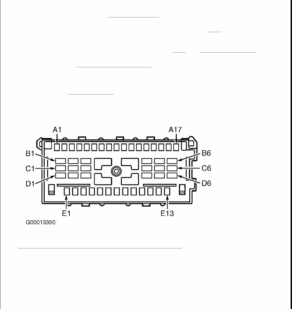
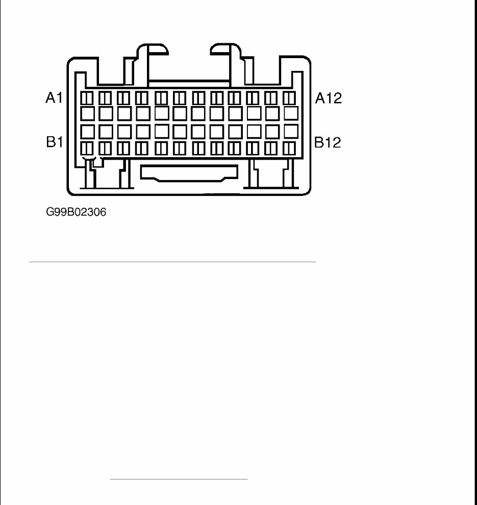
DTCs. If DTC B2947 is listed as a current DTC, go to next step. If B2947 is not listed as a current DTC, problem my be intermittent. See DIAGNOSTIC AIDS . 3. Disconnect Passlock(tm) sensor connector C-201. Using a DVOM, measure voltage between Passlock (tm) sensor connector C-201 terminal C2 (Red/White wire) and ground. See Fig. 1 . If battery voltage is present, go to step 6 . If battery voltage is not present, go to next step. 4. Check Red/White wire between Passlock(tm) sensor connector C-201 terminal C2 and BCM connector C1, terminal B3 for poor connections or short to ground. See Fig. 2 . See WIRING DIAGRAMS . If problem was found, go to step 7 . If problem was not found, go to next step. 5. Replace BCM. See BODY CONTROL MODULE under REMOVAL & INSTALLATION. After repairs, go to step 7 . 6. Check Passlock(tm) sensor connector C201 for poor connections. If connections are okay, replace Passlock(tm) sensor. See appropriate STEERING COLUMN SWITCHES article. Perform auto learn procedure. See PROGRAMMING . After repairs, go to next step. 7. Use scan tool to clear DTCs. Recheck BCM for DTCs. If DTCs do not reset, system is okay. Fig. 1: Identifying Passlock(tm) Sensor Connector C - 201 Terminals Courtesy of GENERAL MOTORS CORP.
Fig. 2: Identifying Body Control Module Connector C1 & C2 Terminals Courtesy of GM Diagnostic Aids If DTC is a history DTC, problem may be intermittent. Perform tests while wiggling wiring. DTC B2948: PASSLOCK(TM) SENSOR POWER CIRCUIT HIGH Circuit Description This DTC sets when ignition is not active (OFF) and Passlock(tm) power feedback is present during 0.1 second check. Vehicle will restart, but SECURITY indicator light will remain illuminated. Diagnostic Procedure 1. If diagnostic system check has been performed, go to next step. If diagnostic system check has not been performed, see DIAGNOSTIC SYSTEM CHECK under SELF-DIAGNOSTIC SYSTEM. 2. Connect scan tool. Turn ignition switch to RUN position, engine off. Using scan tool, check for BCM DTCs. If DTC B2948 is listed as a current DTC, go to next step. If B2948 is not listed as a current DTC, CAUTION: Always remove Brown connector first and install Brown connector last on BCM.
problem my be intermittent. See DIAGNOSTIC AIDS . 3. Disconnect Passlock(tm) sensor connector C-201. Connect a DVOM between Passlock(tm) sensor connector C-201 terminal C2 (Red/White wire) and ground. See Fig. 1 . Set MIN/MAX mode to one millisecond peak and start record. Turn ignition switch to OFF position. Stop recording and review recorded MIN value. If voltage measures near zero volts, go to step (7). If voltage does not measure near zero volts, go to next. 4. Check Red/White wire between Passlock(tm) sensor connector C-201 terminal C2 and BCM connector C1, terminal B3 for short to power. See Fig. 2 . See WIRING DIAGRAMS . Check for poor connections at connectors. If problem was found, go to step 7 . If problem was not found, go to next step. 5. Check Passlock(tm) sensor connector for poor connections. If connections are okay, replace Passlock(tm) sensor. See appropriate STEERING COLUMN SWITCHES article. Perform auto learn procedure. See PROGRAMMING . After repairs, go to next step. 6. Replace BCM. See BODY CONTROL MODULE under REMOVAL & INSTALLATION. After repairs, go to step 7 . 7. Use scan tool to clear DTCs. Recheck BCM for DTCs. If DTCs do not reset, system is okay. Diagnostic Aids If DTC is a history DTC, problem may be intermittent. Perform tests while wiggling wiring. DTC B2957: PASSLOCK(TM) SENSOR DATA CIRCUIT LOW Circuit Description This DTC sets when ignition is active and Passlock(tm) signal is less than .4 volt for one second. If ignition was off, vehicle will not start. If vehicle was running, vehicle will restart, but SECURITY indicator light will remain illuminated. Diagnostic Procedure 1. If diagnostic system check has been performed, go to next step. If diagnostic system check has not been performed, see DIAGNOSTIC SYSTEM CHECK under SELF-DIAGNOSTIC SYSTEM. 2. Connect scan tool. Momentarily rotate ignition switch to START position (do not start engine). Release ignition switch to ON position. With scan tool, observe Passlock(tm) data voltage in BCM security data list. If voltage is not 0.4-4.9 volts, go to next step. If voltage is 0.4-4.9 volts, problem is intermittent. See DIAGNOSTIC AIDS . 3. Turn ignition switch to OFF position. Disconnect Passlock(tm) sensor connector C-201. Turn ignition switch to RUN position, engine off. With scan tool, observe Passlock(tm) data voltage in BCM security data list. If voltage is not greater than 4.9 volts, go to next step. If voltage is greater than 4.9 volts, go to step 6 . 4. Check Yellow wire between Passlock(tm) sensor connector C-201 terminal D3 and BCM connector C1, CAUTION: Always remove Brown connector first and install Brown connector last on BCM.
terminal B3 for short to ground or poor connections. See Fig. 1 and Fig. 2 . See WIRING DIAGRAMS . If problem is found, repair as necessary. After repairs, go to step 7 . If problem is not found, go to next step. 5. Replace BCM. See BODY CONTROL MODULE under REMOVAL & INSTALLATION. After repairs, go to step 7 . 6. Check Passlock(tm) sensor connector C-201 for poor connections. If connections are okay, replace Passlock(tm) sensor. See appropriate STEERING COLUMN SWITCHES article. Perform auto learn procedure. See PROGRAMMING . After repairs, go to next step. 7. Use scan tool to clear DTCs. Recheck BCM for DTCs. If DTCs do not reset, system is okay. Diagnostic Aids If DTC is a history DTC, problem may be intermittent. Perform tests while wiggling wiring. DTC B2958: PASSLOCK(TM) SENSOR DATA CIRCUIT HIGH Circuit Description This DTC sets when ignition is active and Passlock(tm) signal is more than 4.9 volts for one second. Vehicle will restart, but SECURITY indicator light will remain illuminated. Diagnostic Procedure 1. If diagnostic system check has been performed, go to next step. If diagnostic system check has not been performed, see DIAGNOSTIC SYSTEM CHECK under SELF-DIAGNOSTIC SYSTEM. 2. Connect scan tool. Momentarily rotate ignition switch to START position (do not start engine). Release ignition switch to ON position. With scan tool, observe Passlock(tm) data voltage in BCM security data list. If voltage is not 0.4-4.9 volts, go to next step. If voltage is within 0.4-4.9 volts, problem is intermittent. See DIAGNOSTIC AIDS . 3. Turn ignition switch to OFF position. Disconnect Passlock(tm) sensor connector C-201. Turn ignition switch to RUN position, engine off. With scan tool, observe Passlock(tm) data voltage in BCM security data list. If voltage is greater than 4.9 volts, go to next step. If voltage is not greater than 4.9 volts, check connectors at BCM for poor connections. If connections are okay, replace BCM. See BODY CONTROL MODULE under REMOVAL & INSTALLATION. After repairs, go to step 10 . 4. Turn ignition OFF. Connect a 3-amp fused jumper wire between Passlock(tm) sensor connector terminal D3 (Yellow wire) and terminal C4 (Orange/Black wire). See Fig. 1 . Turn ignition switch to RUN position, engine off. Using scan tool, observe Passlock(tm) data voltage in BCM security data list. If voltage is less than 0.4 volt, go to next step. If voltage is more than 0.4 volt, go to step 7 . 5. Disconnect fused jumper wire. Using a DVOM, measure voltage between Passlock(tm) sensor connector C-201 terminal C2 (Red/White wire) and terminal C4 (Orange/Black wire). See Fig. 1 . If voltage is less than 12 volts, go to next step. If voltage is not less than 12 volts, go to step 9 . CAUTION: Always remove Brown connector first and install Brown connector last on BCM.
6. Check Red/White wire between Passlock(tm) connector terminal C2 and BCM connector C1, terminal B3 for open or poor connections. See Fig. 2 . See WIRING DIAGRAMS . If wire and connections are okay, replace BCM. See BODY CONTROL MODULE under REMOVAL & INSTALLATION. After repairs, go to step 10 . 7. Check Yellow wire between Passlock(tm) connector terminal D3 and BCM connector C2, terminal B3 for short to voltage, high resistance or open. See WIRING DIAGRAMS . If wire and connections are okay, go to next step. If problem is found, repair as necessary. After repairs, go to step 10 . 8. Check Orange/Black wire between Passlock(tm) connector terminal C4 and BCM connector C2, terminal A2 for high resistance, open or poor connections. See WIRING DIAGRAMS . If wire and connections are okay, replace BCM. See BODY CONTROL MODULE under REMOVAL & INSTALLATION. If problem is found, repair as necessary. After repairs, go to step 10 . 9. Check Passlock(tm) sensor connector for poor connections. If connections are okay, replace Passlock(tm) sensor. See appropriate STEERING COLUMN SWITCHES article. Perform auto learn procedure. See PROGRAMMING . After repairs, go to next step. 10. Use scan tool to clear DTCs. Turn ignition switch to OFF position. Momentarily turn ignition switch to START position (do not start engine). Release key to RUN position. Using scan tool, check BCM for DTCs. If DTCs do not reset, attempt to start engine. If engine starts and runs, system is okay. Diagnostic Aids Inspect Passlock(tm) sensor harness for an intermittent or short to battery voltage. If DTC is a history DTC, problem may be intermittent. Perform tests while wiggling wiring. DTC B2960: PASSLOCK(TM) SENSOR DATA INCORRECT BUT VALID Circuit Description This DTC sets when ignition is active, Passlock(tm) signal is not open or grounded, correct key was used, but code does not equal learned key (Passlock(tm) sensor) code during engine start or for one second at any time during ignition cycle. System enters tamper mode. If ignition was off, vehicle will not start and SECURITY indicator light will flash. If vehicle was running, vehicle will restart, but SECURITY indicator light will remain illuminated. This DTC may be set if Passlock(tm) sensor was replaced and reprogramming procedure was not performed. Diagnostic Procedure 1. If diagnostic system check has been performed, go to next step. If diagnostic system check has not been performed, see DIAGNOSTIC SYSTEM CHECK under SELF-DIAGNOSTIC SYSTEM. 2. Connect scan tool. Momentarily turn ignition switch to START position (do not start engine). Release key to RUN position. Using scan tool, check BCM for DTCs. If DTC B2960 is set as current, go to next step. If DTC B2960 is not set as current, problem is intermittent. See DIAGNOSTIC AIDS . 3. If scan tool displays DTC B2947, B2948, B2957 or B2958, perform appropriate diagnostic procedure for CAUTION: Always remove Brown connector first and install Brown connector last on BCM.
This 2001-2005 Chevrolet Silverado 1500 Service & Repair Manual is a comprehensive guide for owners of Chevrolet Silverado 1500 trucks from the years 2001 to 2005. Whether you are a professional mechanic or a do-it-yourself enthusiast, this manual is essential for maintaining and repairing your vehicle.
With detailed instructions and illustrations, this manual covers a wide range of maintenance and repair tasks, including:
Engine
Transmission
Brakes
Suspension
Electrical system
Heating and air conditioning
Steering
Body and interior
And much more
Whether you need to troubleshoot a specific issue, perform routine maintenance, or complete a major overhaul, this manual provides you with the step-by-step instructions and diagrams you need. It is organized in a user-friendly format, allowing you to quickly find the information you are looking for.
Don't waste time and money at the auto shop. With this service and repair manual, you will have the knowledge and confidence to tackle any repair or maintenance task on your Chevrolet Silverado 1500 from 2001 to 2005.
Recently Viewed
5,521,897Happy Clients
2,594,462eManuals
1,120,453Trusted Sellers
15Years in Business
Price:
Actual Price:
2001-2005 Chevrolet Silverado 1500 Service & Repair Manual