ENGINE OVERHAU L
1994 GENERAL MOTORS ENGINES 4.3L V6
ENGINE IDENTIFICATION
Engine is identified by eighth character of Vehicle Identification Number (VIN). VIN is stamped on a metal tag
on top left end of instrument panel, near windshield. See the ENGINE IDENTIFICATION CODES table.
Engine can also be identified by engine identification (ID) number. Number is stamped on front of cylinder
block, immediately forward of right cylinder head or on left side of cylinder block, on engine-to-transmission
mating flange.
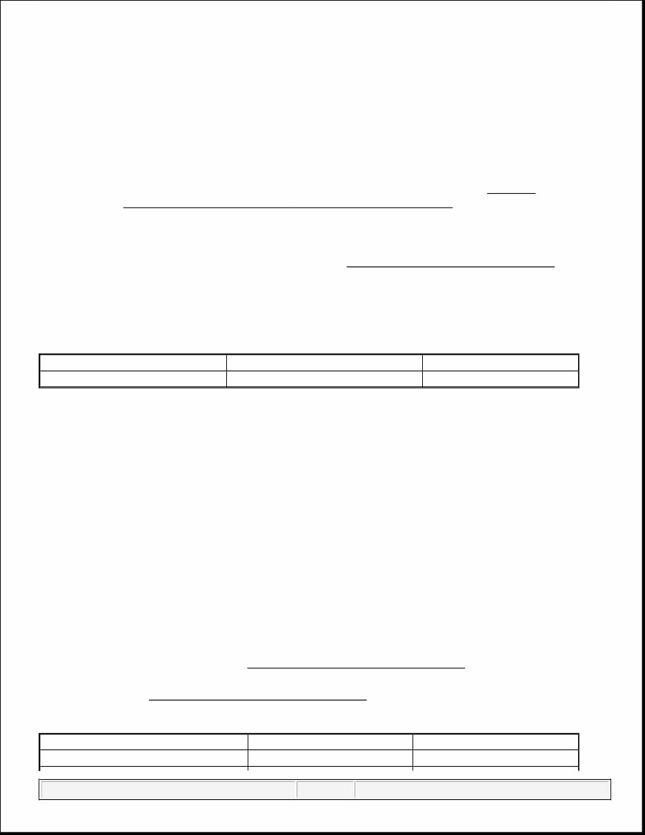
ENGINE IDENTIFICATION CODES
ADJUSTMENTS
VALVE CLEARANCE ADJUSTMENT
With Screw-In Rocker Studs
Tighten rocker arm nuts to 20 ft. lbs. (27 N.m).
With Pressed-In Rocker Studs
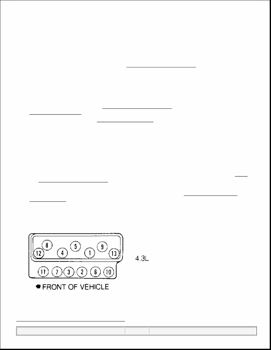
1. Rotate engine until No. 1 piston is on TDC of compression stroke. Loosen rocker arm adjusting nut until
lash is present.
2. Tighten adjusting nut until lash is removed. Tighten adjusting nut one full turn. Adjust remaining valves
(for piston at TDC) as listed in the VALVE CLEARANCE ADJUSTMENT table.
3. Rotate crankshaft 360 degrees to bring No. 4 piston to TDC of compression stroke. Adjust remaining
valves. See the VALVE CLEARANCE ADJUSTMENT table.
VALVE CLEARANCE ADJUSTMENT
(1)
NOTE: For engine repair procedures not covered in this article, see ENGINE
OVERHAUL PROCEDURES - GENERAL INFORMATION article in the GENERAL
INFORMATION section.
Application Engine Code VIN Code
4.3L V6 TBI LB4 Z
NOTE: Although valve clearance adjustment is not usually required (because the
engine uses hydraulic valve lifters), perform the following procedures after
servicing valve train.
Piston At TDC Intake Exhaust
No. 1 No. 1, 2 & 3 No. 1, 5 & 6 Tuesday, May 23, 2017 3:19:00 PM Page 1 © 2011 Mitchell Repair Information Company, LLC.
REMOVAL & INSTALLATION
GENERAL PRECAUTION
FUEL PRESSURE RELEASE
Disconnect battery terminals. Loosen fuel tank cap to relieve tank pressure. Internal constant bleed feature in
injection unit relieves fuel system pressure when ignition switch is turned off. No further pressure relief is
required.
ENGINE R & I
Removal & Installation (Commercial Van)
1. Release fuel system pressure. See FUEL PRESSURE RELEASE . Disconnect battery. Drain cooling
system. Remove engine cover and floor panel sections.
2. Remove air cleaner, duct and exhaust heat stove pipe. Remove distributor cap and position aside.
Disconnect all engine harness electrical connectors and position aside. Disconnect fuel lines from
injection unit. Remove fuel line clamps from transmission and position fuel lines aside.
3. Disconnect ground strap from rear end of left cylinder head. Disconnect all transmission harness electrical
connectors and position harness aside. Remove transmission shifter (if necessary). Remove upper radiator
hose, all accessory drive belts, fan, fan pulley, fan shroud and lower radiator hose.
4. Remove engine oil filler tube. Remove clutch adjuster rod, return spring and pivot arm assembly (M/T).
Disconnect exhaust pipes from manifolds. Disconnect battery cable from clamp on cylinder block.
No. 4 No. 4, 5 & 6 No. 2, 3 & 4
(1)
If equipped with screw-in rocker studs, tighten all rocker arm nuts to 20 ft. lbs. (27 N.m).
CAUTION: When battery is disconnected, vehicle computer and memory systems
may lose memory data. Driveability problems may exist until computer
systems have completed a relearn cycle. See COMPUTER RELEARN
PROCEDURES article in GENERAL INFORMATION before disconnecting
battery.
NOTE: For reassembly reference, label all electrical connectors, vacuum hoses and
fuel lines before removal. Also place mating marks on engine hood and other
major assemblies before removal.
CAUTION: Minimal clearance exists between oil pump pick-up tube and bottom of oil
pan. DO NOT place jack under oil pan, crankshaft pulley or any sheet
metal when lifting engine.
NOTE: On Commercial Van, engine and transmission are removed as an assembly
through side door.
Tuesday, May 23, 2017 3:18:57 PM Page 2 © 2011 Mitchell Repair Information Company, LLC.
Disconnect drive shaft from transmission. Remove transmission mount.
5. Disconnect oil cooler lines from oil filter adapter and oil cooler line clamps from engine. Attach engine
hoist. Remove engine mount through-bolts. Remove engine and transmission assembly through side door.
To install, reverse removal procedure. Fill crankcase and cooling system.
Removal & Installation (Van)
1. Release fuel system pressure. See FUEL PRESSURE RELEASE . Disconnect battery. Drain cooling
system. Remove engine cover and air cleaner. Remove power steering fluid reservoir.
2. Remove upper fan shroud, fan, fan pulley, radiator and lower fan shroud. Discharge A/C system (if
equipped) using approved refrigerant recovery/recycling equipment. Remove A/C condenser. Remove
A/C compressor and brace. Remove alternator. Remove cruise control servo (if equipped).
3. Disconnect fuel lines, electrical connectors, vacuum hoses, coolant hoses and control cables as necessary.
Remove injection unit. Remove distributor cap with wires attached. Remove diverter valve assembly and
pipe.
4. Remove ignition coil and manifold absolute pressure sensor. Remove upper half of engine oil dipstick
tube. Remove engine oil filler tube. Remove headlight bezels, grille and upper radiator support (sheet
metal cross panel support).
5. Raise and support vehicle. Drain crankcase. Disconnect exhaust pipes from manifolds. Remove strut rods.
Remove flywheel cover. Disconnect oil cooler lines from engine. Remove starter, torque converter bolts
(A/T) and engine mount through-bolts.
6. Lower vehicle. Attach engine hoist. Remove bellhousing bolts. Support transmission. Remove engine. To
install, reverse removal procedure. Fill crankcase and cooling system. Evacuate and charge A/C system.
INTAKE MANIFOLD
Removal
1. Release fuel system pressure. See FUEL PRESSURE RELEASE . Disconnect battery. Drain cooling
system. Remove air cleaner.
2. Disconnect fuel lines, electrical connectors, vacuum hoses, coolant hoses and control cables as necessary.
Remove alternator bracket, A/C compressor (with hoses attached), injection unit and cruise control servo
as necessary.
3. Remove distributor cap. Mark distributor rotor in relation to distributor housing. Mark base of distributor
housing in relation to intake manifold. Remove distributor. Remove intake manifold bolts, intake
manifold and gaskets.
Installation
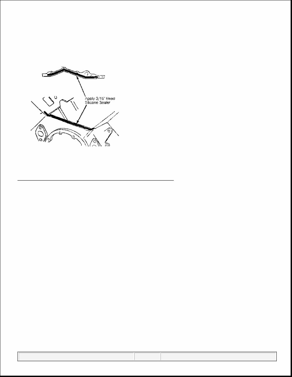
1. Install gaskets on cylinder heads. Apply a 3/16" bead of RTV silicone sealant to front and rear intake
manifold-to-cylinder block mounting surfaces. See Fig. 1 . Extend bead 1/2" beyond cylinder block-to-
cylinder head junction.
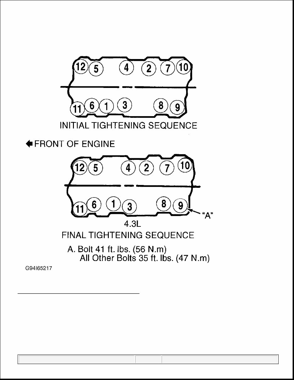
2. Install intake manifold and bolts. Tighten bolts in sequence to specification. See Fig. 2 . See TORQUE
SPECIFICATIONS . To com p lete installation, reverse removal p rocedure. Fill coolin g s y stem.
Tuesday, May 23, 2017 3:18:57 PM Page 3 © 2011 Mitchell Repair Information Company, LLC.
Fig. 1: Applying RTV Sealant Before Installing Intake Manifold
Courtes y of GENERAL MOTORS CORP .
Tuesday, May 23, 2017 3:18:57 PM Page 4 © 2011 Mitchell Repair Information Company, LLC.
Fig. 2: Intake Manifold Bolt Tightening Sequence
Courtesy of GENERAL MOTORS CORP.
EXHAUST MANIFOLD
Removal
1. Remove heat stove tube. Remove all attached brackets and heat shields. If necessary, remove dip stick
tube. Disconnect ox yg en sensor electrical connector.
Tuesday, May 23, 2017 3:18:57 PM Page 5 © 2011 Mitchell Repair Information Company, LLC.
2. Disconnect exhaust pipe from manifold. Remove exhaust manifold bolts and exhaust manifold.
Installation
Install manifold. Tighten bolts to specification. See TORQUE SPECIFICATIONS . Bend lock tabs (if
equipped). To complete installation, reverse removal procedure.
CYLINDER HEAD
Removal
1. Release fuel system pressure. See FUEL PRESSURE RELEASE . Remove intake manifold. See
INTAKE MANIFOLD .
2. Remove exhaust manifold. See EXHAUST MANIFOLD . Remove valve covers. Loosen rocker arm
nuts. Rotate rocker arms aside. Remove push rods and mark for reassembly to original locations. Remove
cylinder head bolts. Remove cylinder head.
Installation
1. Clean gasket surfaces, bolt threads and bolt holes. If using steel head gasket, thinly coat both sides of
gasket with sealant. DO NOT apply sealant to composition (steel/asbestos) head gaskets. Position head
gasket on cylinder block. Ensure all holes align. Coat head bolt threads with GM Sealant (1052080).
2. Install cylinder head with bolts finger-tight. Tighten head bolts in sequence to specification. See Fig. 3 .
See TORQUE SPECIFICATIONS . Lubricate valve tip, rocker arm pivot and push rod socket with
Molykote.
3. To complete installation, reverse removal procedure. Adjust valves. See VALVE CLEARANCE
ADJUSTMENT under ADJUSTMENTS.
Fig. 3: Cylinder Head Bolt Tightening Sequence
Tuesday, May 23, 2017 3:18:57 PM Page 6 © 2011 Mitchell Repair Information Company, LLC.
Courtes y of GENERAL MOTORS CORP .
FRONT COVER OIL SEAL
Removal
Remove accessory drive belt(s) and pulley. Remove crankshaft damper bolt. Using Damper Puller/Installer (J-
39046), remove crankshaft damper. Pry seal from cover.
Installation
1. Coat seal lip with engine oil. Using Seal Installer (J-35468), install NEW seal in front cover with seal lip
facing engine. Apply RTV sealant to Woodruff keyway in crankshaft damper.
2. Install crankshaft damper. Install crankshaft damper bolt and tighten to specification. See TORQUE
SPECIFICATIONS . To install remaining components, reverse removal procedure.
TIMING CHAIN & SPROCKETS
Removal
1. Disconnect battery. Drain cooling system. If necessary, remove radiator shroud. Remove accessory drive
belts, fan and pulley. Remove crankshaft damper bolt. Using Damper Puller/Installer (J-39046), remove
crankshaft damper.
2. Remove all mounting brackets and coolant hoses attached to water pump. Remove water pump. Remove
oil pan. See OIL PAN. Remove front cover and gasket.
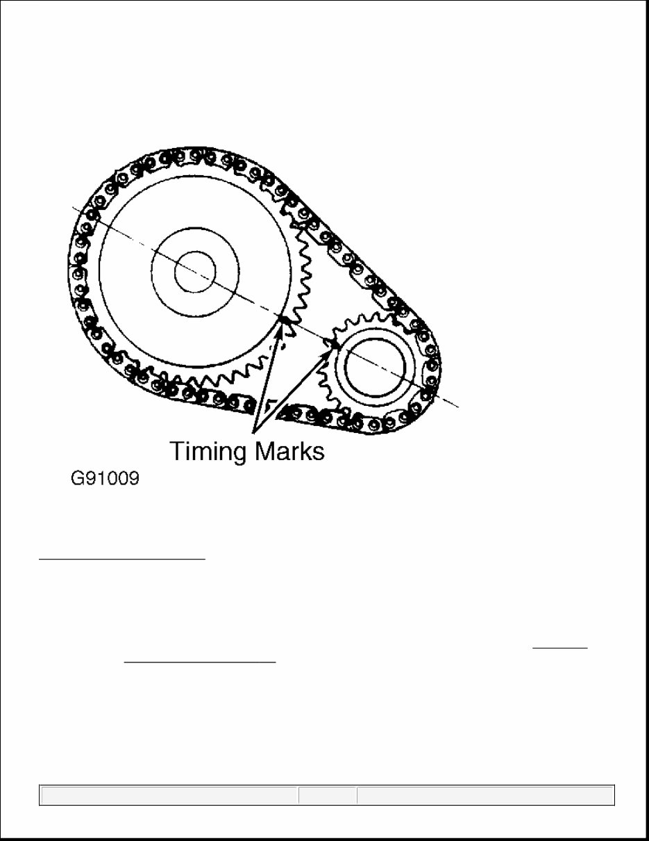
3. Rotate crankshaft until timing marks on camshaft and crankshaft sprockets are aligned. See Fig. 4 .
Remove camshaft sprocket and timing chain. To remove crankshaft sprocket, use Sprocket Puller (J-
5825-A).
Installation
1. Install Woodruff key in crankshaft (if removed). Using Crankshaft Sprocket Installer (J-5590), install
crankshaft sprocket. Install camshaft sprocket and timing chain, ensuring timing marks on sprockets are
aligned. See Fig. 4 .
2. Install and tighten camshaft sprocket bolts to specification. See TORQUE SPECIFICATIONS . Install
gasket to front cover with gasket sealant. Install front cover and gasket.
3. Apply RTV sealant to Woodruff keyway in crankshaft damper. Install crankshaft damper. Install
crankshaft damper bolt and tighten to specification. See TORQUE SPECIFICATIONS . To complete
installation, reverse removal procedure.
CAUTION: If engine is equipped with a balance shaft, the timing gear sprocket
marks align at TDC of cylinder No. 4.
Tuesday, May 23, 2017 3:18:57 PM Page 7 © 2011 Mitchell Repair Information Company, LLC.
Fig. 4: Aligning Timing Marks
Courtesy of GENERAL MOTORS CORP.
ROCKER ARM STUDS (PRESS-FIT)
Removal & Installation
1. Rocker arm studs are pressed into c y linder head. Usin g Stud Remover ( J -580 2 -01), place remover ove r
NOTE: Some engines are equipped with press-fit, others with screw-in. This procedure
is for the press-fit type. If engine is equipped with screw in, refer to ROCKER
ARM STUDS (SCREW - IN) .
CAUTION: Ream rocker arm stud bore before installing oversize rocker arm stud, or
cylinder head may be damaged.
Tuesday, May 23, 2017 3:18:57 PM Page 8 © 2011 Mitchell Repair Information Company, LLC.
stud. Install flat washer and nut. Tighten nut to remove stud from cylinder head.
2. If stud is loose in cylinder head, ream stud bore for oversize stud using Reamer (J-5715) for .003" (.08
mm) oversize stud or (J-6036) for .013" (.33 mm) oversize stud.
3. Coat press-fit area of stud with hypoid axle lubricant. Using Stud Driver (J-6880), drive stud into bore
until driver bottoms against cylinder head.
ROCKER ARM STUDS (SCREW-IN)
Removal & Installation
Unscrew rocker arm stud from cylinder head. To install, insert NEW rocker arm stud and tighten to 35 ft. lbs.
(47 N.m).
VALVE LIFTERS
Removal
1. Remove intake manifold. See INTAKE MANIFOLD . Remove valve covers. Loosen all rocker arm nuts
and rotate rockers aside.
2. Remove push rods, noting location for reassembly reference. Remove lifter retainer. Remove roller lifter
guides (if equipped). Remove lifters, noting location for reassembly reference.
Installation
Coat lifter base or roller (if equipped) and body with High Viscosity Oil/Zinc (12345501). Install lifters in
original location. To complete installation, reverse removal procedure.
CAMSHAFT
Removal
1. Remove radiator. Discharge A/C system (if equipped) using approved refrigerant recovery/recycling
equipment and remove A/C condenser (if equipped) and grille. Remove valve lifters. See VALVE
LIFTERS .
2. Remove timing chain and camshaft sprocket. See TIMING CHAIN & SPROCKETS . Remove balance
shaft gear (if equipped). Remove thrust plate. If necessary, raise engine. Remove camshaft.
Installation
Coat camshaft lobes and bearing journals with High Viscosity Oil/Zinc (12345501). Install camshaft. To
complete installation, reverse removal procedure.
BALANCE SHAFT (IF EQUIPPED)
NOTE: Some engines are equipped with press-fit, others with screw-in type. This
procedure is for the screw-in type. If engine is equipped with press-fit type, see
ROCKER ARM STUDS (PRESS - FIT) .
Tuesday, May 23, 2017 3:18:57 PM Page 9 © 2011 Mitchell Repair Information Company, LLC.
Removal
1. Remove radiator. Discharge A/C system (if equipped) using approved refrigerant recovery/recycling
equipment and remove A/C condenser (if equipped) and grille. Remove valve lifters. See VALVE
LIFTERS .
2. Remove timing chain and camshaft sprocket. See TIMING CHAIN & SPROCKETS . Remove balance
shaft gears. Remove balance shaft retainer plate.
3. Remove intake manifold. See INTAKE MANIFOLD . Using a soft-faced hammer, tap balance shaft out
toward front of engine.
Installation
1. Apply oil to balance shaft bearings. Using Installers (J-36996 and J-8092), install balance shaft in block.
See Fig. 5 . Install lifter retainer (if equipped). Ensure balance shaft turns.
2. Install thrust plate. Install balance shaft gears. Ensure timing marks on balance shaft gears are aligned.
See Fig. 6 . Install balance shaft timing gear bolt. Tighten bolt to 15 ft. lbs. (20 N.m). Then tighten bolt an
additional 35 degrees. To complete installation, reverse removal procedure.
NOTE: Front bearing is removed with balance shaft. Replace front bearing and balance
shaft as a set only. Replace balance shaft timing gears as a set only.
Tuesday, May 23, 2017 3:18:57 PM Page 10 © 2011 Mitchell Repair Information Company, LLC.
You're Reading a Preview
What's Included?
Lifetime Access
Access PDF Contents & Bookmarks
Print one or all pages of your manual