10. With an assistant ready, raise and support the vehicle. Refer to Lifting and Jacking the Vehicle . Note: 11. Perform the automated bleed procedure as instructed by the scan tool. 12. If the automated bleed procedure is aborted, a malfunction exists. If a DTC is detected, refer to Diagnostic Trouble Code (DTC) List - Vehicle to diagnose the DTC. 13. After completion of the automated bleed procedure, press and hold the brake pedal to inspect for pedal firmness. 14. If the brake pedal feels spongy, repeat the bleed procedure completely. 15. Remove the scan tool. 16. Install the tire and wheel assemblies. Refer to Tire and Wheel Removal and Installation . 17. Lower the vehicle. 18. Adjust the brake fluid level. Refer to Master Cylinder Reservoir Filling . 19. Road test the vehicle while confirming the brake pedal remains high and firm. 9.4. Select Electronic Brake Control Module (EBCM) 9.5. Select Special Functions 9.6. Select Automated Bleed • Apply the brake pedal when instructed, using moderate effort. • Ensure the pedal remains applied until instructed to release by the scan tool. • Do not exceed the time period allowed by the scan tool for having the bleeder valves open. • The bleed sequence for each corner is as follows: - Left front - Right front - Right rear - Left rear Page 2 of 2 Document ID: 2041886 6/2/2010 http://localhost:9001/si/showDoc.do?docSyskey=2041886&pubCellSyskey=1238&pubObj...
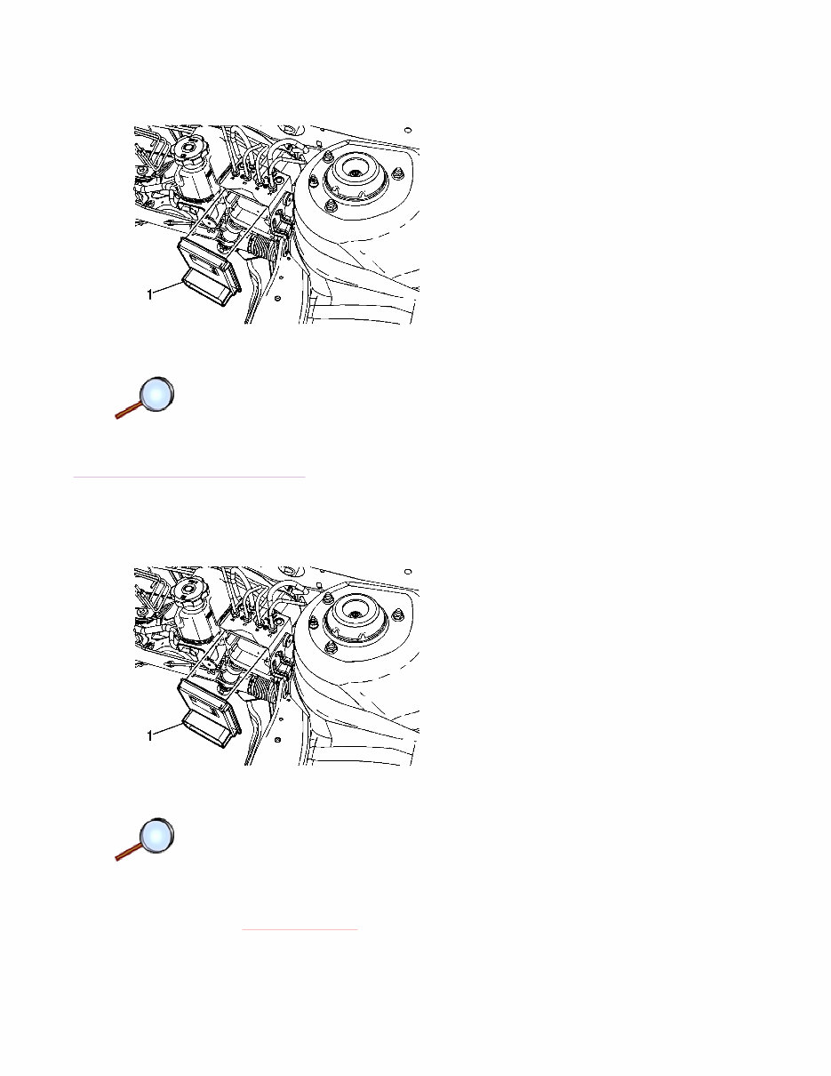
5. Separate the EBCM (1) from the BPMV by carefully pulling the components apart. Installation Procedure 1. Clean the sealing surface of the BPMV with denatured alcohol and a clean shop cloth. 2. Carefully install the EBCM (1) to the BPMV. Caution: Refer to Fastener Caution in the Preface section. Page 2 of 3 Document ID: 2041846 6/2/2010 http://localhost:9001/si/showDoc.do?docSyskey=2041846&pubCellSyskey=954&pubObjS...
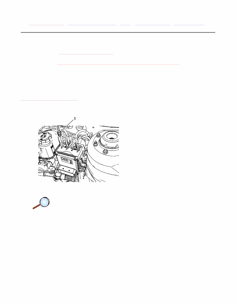
3. Install the 4 EBCM bolts (1). Tighten the bolts in a cross pattern to 3 N·m (27 lb in). Note: Ensure the electrical connector is correctly inserted into the EBCM prior to placing the locking lever into position. Failure to make a proper connection may cause communication problems with the module. 4. Connect the electrical connector to the EBCM. 5. If installing a new EBCM, it is necessary to program the EBCM. Refer to Control Module References . Page 3 of 3 Document ID: 2041846 6/2/2010 http://localhost:9001/si/showDoc.do?docSyskey=2041846&pubCellSyskey=954&pubObjS...
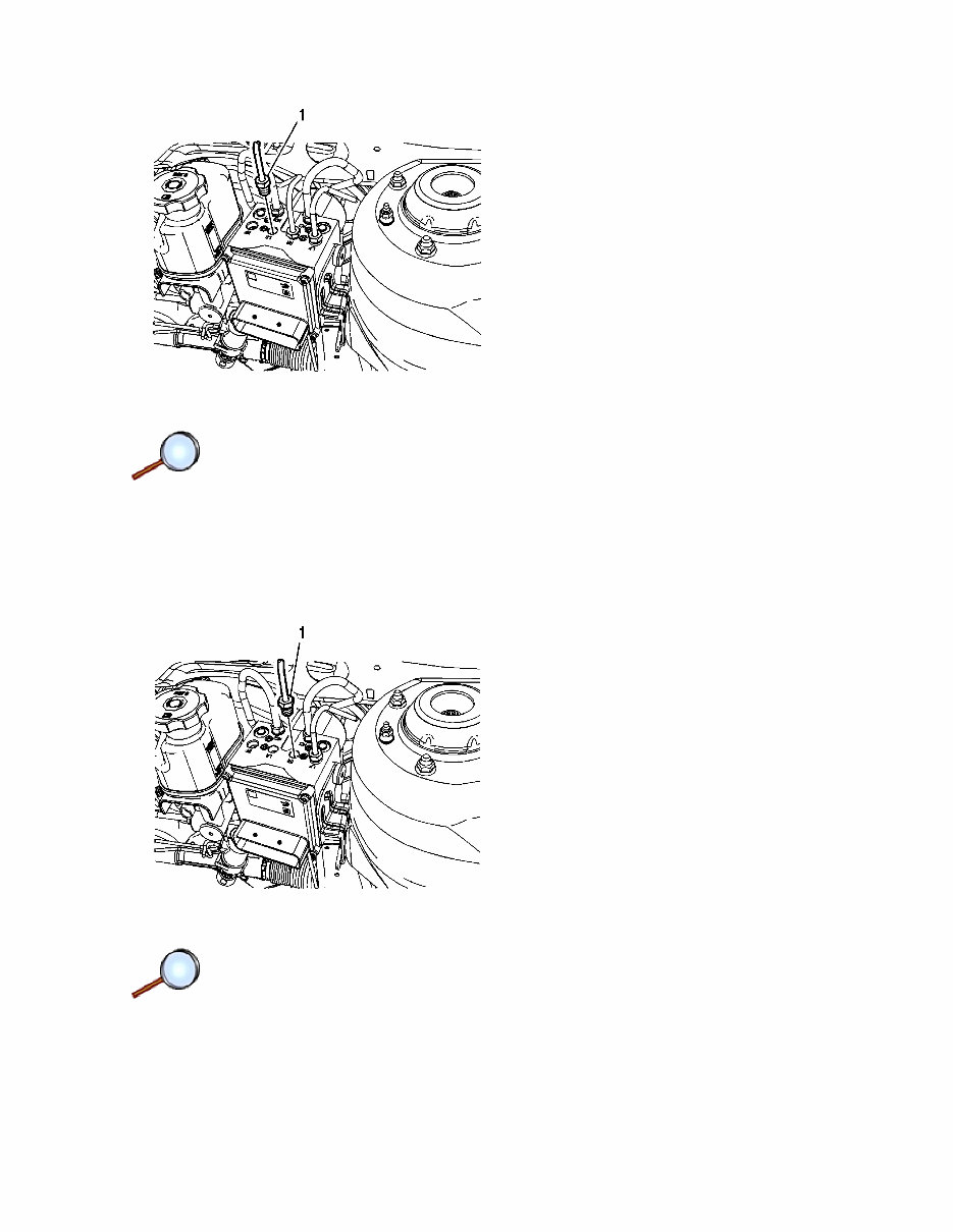
6. Disconnect the LR brake pipe fitting (1). Cap the brake pipe fitting and plug the BPMV outlet port to prevent brake fluid loss and contamination. 7. Disconnect the rear brake pipe fitting (1). Cap the brake pipe fitting and plug the BPMV outlet port to prevent brake fluid loss and contamination. Page 2 of 10 Document ID: 2041850 6/2/2010 http://localhost:9001/si/showDoc.do?docSyskey=2041850&pubCellSyskey=1189&pubObj...
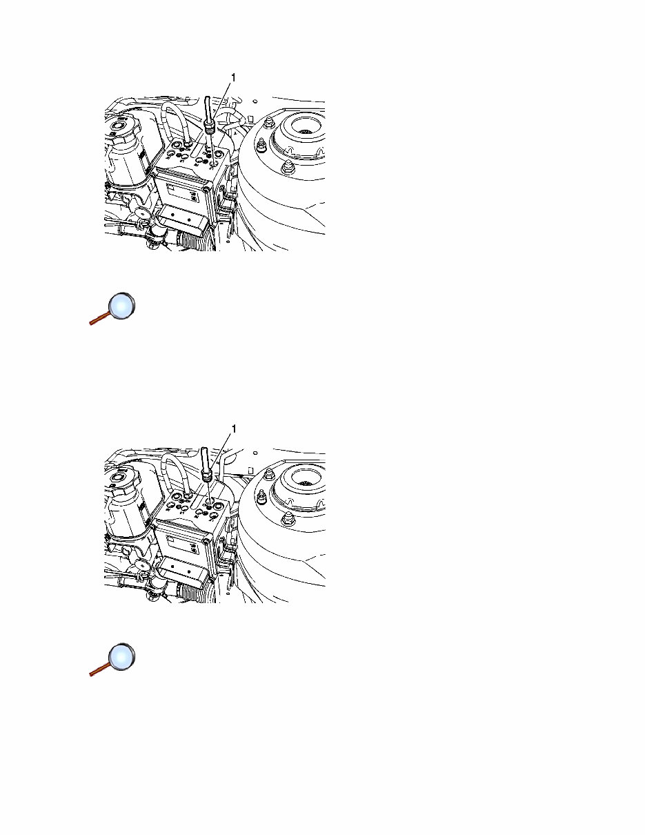
8. Disconnect the left front brake pipe fitting (1). Cap the brake pipe fitting and plug the BPMV outlet port to prevent brake fluid loss and contamination. 9. Disconnect the master cylinder primary brake pipe fitting (1). Cap the brake pipe fitting and plug the BPMV inlet port to prevent brake fluid loss and contamination. Page 3 of 10 Document ID: 2041850 6/2/2010 http://localhost:9001/si/showDoc.do?docSyskey=2041850&pubCellSyskey=1189&pubObj...
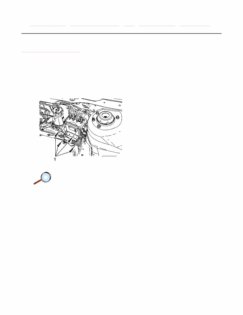
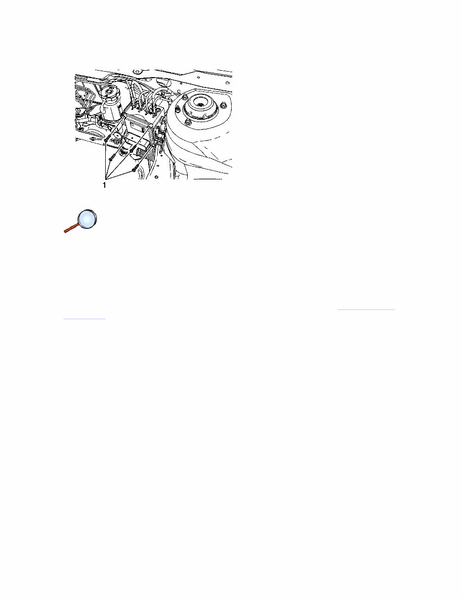
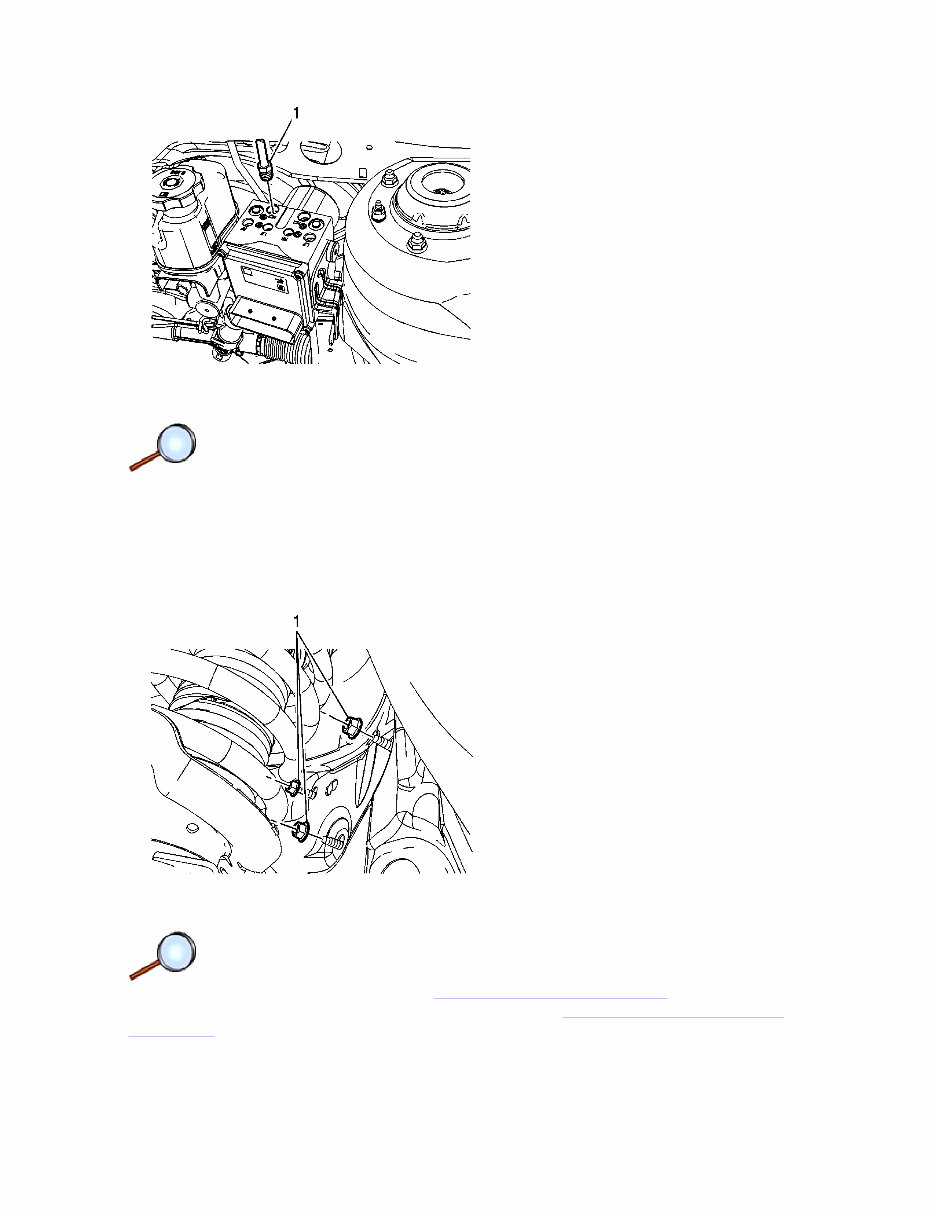
10. Disconnect the master cylinder secondary brake pipe fitting (1). Cap the brake pipe fitting and plug the BPMV inlet port to prevent brake fluid loss and contamination. 11. Raise and support the vehicle. Refer to Lifting and Jacking the Vehicle . 12. Remove the left front tire and wheel assembly. Refer to Tire and Wheel Removal and Installation . 13. Remove the 3 BPMV bracket nuts (1). 14. Remove the BPMV and bracket assembly. Page 4 of 10 Document ID: 2041850 6/2/2010 http://localhost:9001/si/showDoc.do?docSyskey=2041850&pubCellSyskey=1189&pubObj...
The 2008-2010 Chevrolet Malibu Service & Repair Manual is a comprehensive guide designed for owners and professional mechanics working on Chevrolet Malibu models from 2008 to 2010. It offers detailed instructions, step-by-step procedures, and technical insights for vehicle maintenance, repairs, and servicing.
Key features of the 2008-2010 Chevrolet Malibu Service & Repair Manual include:
Coverage of Chevrolet Malibu models from 2008, 2009, and 2010.
Detailed explanations of various vehicle components and systems.
Step-by-step instructions for performing routine maintenance tasks such as oil changes, tire rotations, and brake pad replacements.
Troubleshooting guides to aid in diagnosing and resolving common issues.
Inclusion of wiring diagrams and electrical schematics for easy understanding of the vehicle's electrical system.
Specifications and technical data to ensure accurate and effective repairs.
Whether you are a professional mechanic or a Chevrolet Malibu owner who prefers to perform your own repairs, the 2008-2010 Chevrolet Malibu Service & Repair Manual is an essential tool for maintaining your vehicle. With its detailed instructions and comprehensive coverage, this manual provides the assistance needed to keep your Chevrolet Malibu running smoothly.
Recently Viewed
5,521,897Happy Clients
2,594,462eManuals
1,120,453Trusted Sellers
15Years in Business
Price:
Actual Price:
2008-2010 Chevrolet Malibu Service & Repair Manual