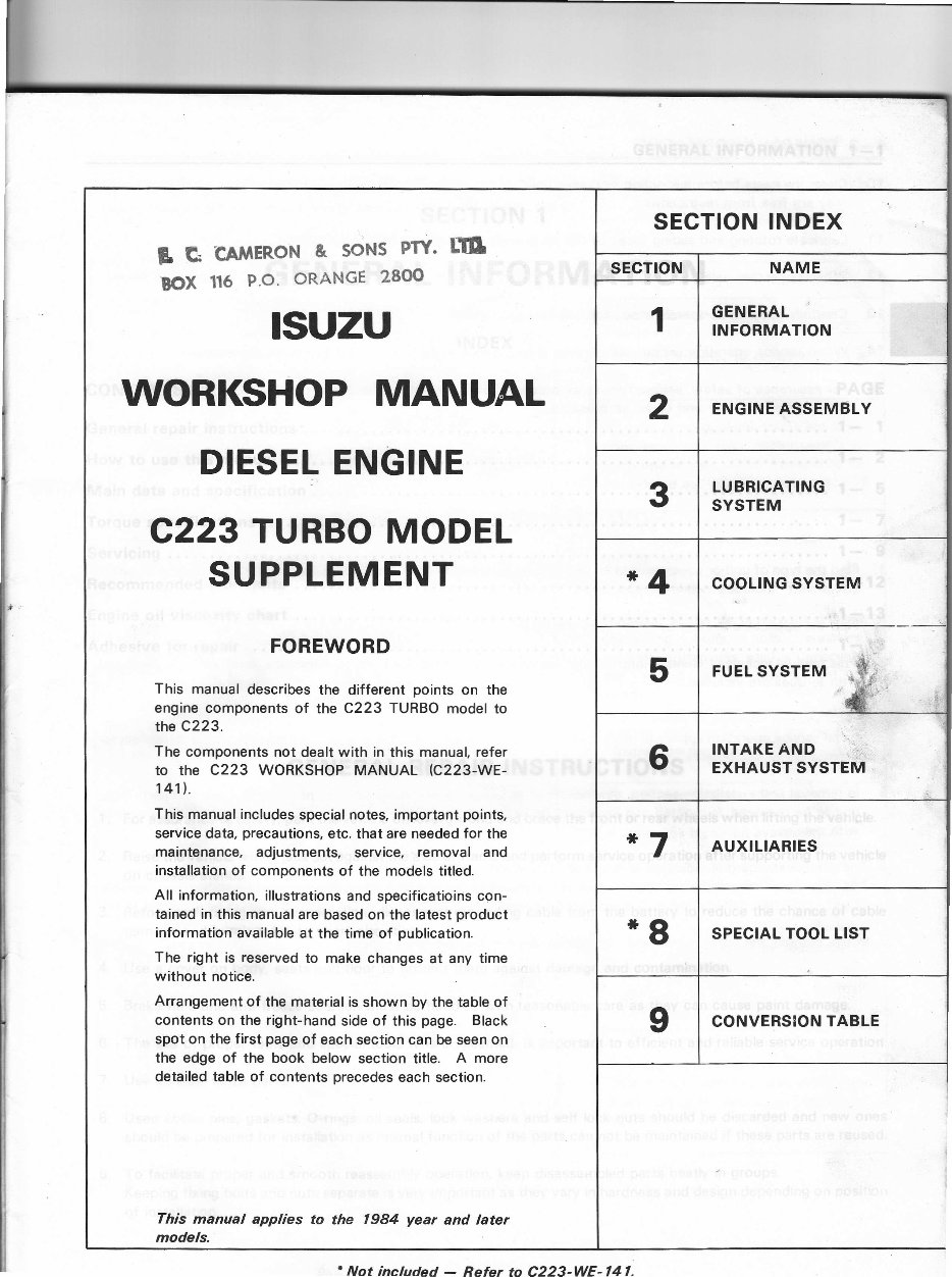
* g G -CAMERON & SONS PTY. BOX 116 P.O. oRANGE 2800 rrl ISUZU WORKSHOP MANUAL DIESEL ENGINE C223 TURBO MODEL SUPPLEMENT FOREWORD This manual describes the different points on the engine components of the C223 TURBO model to the c223. The components not dealt with in this manual, refer to the C223 WORKSHOP MANUAL rc223-WE- 141l,. This manual includes special notes, important points, service data, precautions, etc. that are needed for the maintenance, adjustments, service, removal and installation of components of the models titled. All information, illustrations and specificatioins con- tained in this manual are based on the latest product information available at the time of publication. The right is reserved to make changes at any time without notice. Arrangement of the material is shown by the table of contents on the right-hand side of this page. Black spot on the first page of each section can be seen on the edge of the book below section title. A more detailed table of contents precedes each section. This manual applies models. 1984 year and later SECTION INDEX SECTION NAME 1 GENERAL INFORMATION 2 ENGINE ASSEMBLY 3 LUBRICATING SYSTEM *4 COOLING SYSTEM 5 FUEL SYSTEM s -.\$ si ir 6 INTAKE AND EXHAUST SYSTEM *7 AUXILIARIES *8 SPECIAL TOOL LIST I CONVERSION TABLE 'Not included - Refer to C223-WE-141.
GENERAL INFORMATION 1_1 sEcTloN 1 GENERAL INFORMATION INDEX CoNTENTS PAGE Generat repairinstructions.... ....1- 1 How to use this manual . . . . 1- 2 Maindataandspecification .......1- 5 Torquespecifications ..'.'. 1- 7 Servicing '.....1- I Recommended lubricants .. . 1-12 Engineoil viscositychart ...1-13 Adhesive for repair GENERAL REPAIR INSTRUCTIONS 1. For assurance of safety, park the vehicle on level ground and brace the front or rear wheels when lifting the vehicle. 2. Raise the vehicle with a jack set against the axle or frame and perform service operation after supporting the vehicle on chassis stands. 3. Before performing service operation, disconnect grounding cable from the battery to reduce the chance of cable damage and burning due to short-circuiting. 4. Use a cover on body, seats and floor to protect them against damage and contamination. 5. Brake fluid and anti-freeze solution must be handled with reasonable care as they can cause paint damage' 6. The use of proper tools and special tools where specified, is important to efficient and reliable service operation. 7. Use genuine lsuzu parts. 8. Used cotter pins, gaskets, O-rings, oil seals, lock washers and self lock nuts should be discarded and new ones should be prepared for installation as normal function of the parts can not be maintained if these parts are reused. 9. To facilitate proper and smooth reassembly operation. keep disassembled parts neatly in groups. Keeping fixing bolts and nuts separate is very important as they vary in hardness and design depending on position of installation.
1 -2 GENERAL INFORMATION 10. Clean the parts before inspection or reassembly. Also clean oil ports, etc. using compressed air to make certain they are free from restrictions. 1 1. Lubricate rotating and sliding faces of the parts with oil or grease before installation. 12. When necessary, use a sealer on gaskets to prevent leakage. 13. Carefully observe all specifications for bolt and nut torques. 14, When service operation is completed, make a final check to be sure service has been done properly. 15. For assurance of safety, always release air pressure solely from the air tanks before disconnecting pipes, hoses or other parts from any unit under air pressure. HOW TO USE THIS MANUAL Find the Wpe of unit or equipment to be serviced by referring to the "Application chart" or "ldentification of unit or equipment" included in this section. Find the applicable section by refering to the index. This manual includes "General information" section in which service data, maintenance items and specifications with torques are included. Each section includes removal and installation, disassembly, inspection and repair and reassembly. When the same service operation applies to more than one un;ts or equipments. notice is inserted stating, "Refer to manual for other units or equipments". ln removal and installation section. description of self-explanatory items such as removal of individual parts from unit to be removed, is omitted and important operation such as adjustments, torque specifications, etc. are dealt with mainly. 6. The service standard is indicated in terms of "Standard" and "Limit". The "standard" means the assembly standard and standard range within which the parts are considered serviceable. "Limit" indicates the limit value (Correction or replacement is necessary when measurement is beyond this limit.) 7. ln this manual, the components and parts are printed in singular form. 1. ,4' 2. 3. 4. 5.
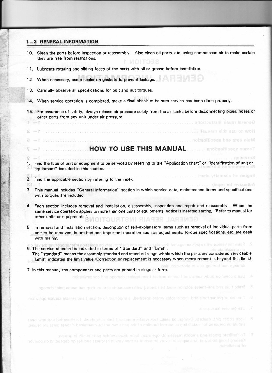
GENERAL INFORMATION 1-3 8. Each service operation section begins with disassembled view of unit or equipment which is useful to find compo- nents, service procedure, availability and content of repair kits, etc. MA'OR COMPONENT Thi, illurtration b b.!.d on th. 6 r 6 and 4 r 4 modolr. Tha ltaF of srvice otsralaon d..iFat d as No. 3 - 12 are eppliQble to sll modclr €rcluding 6 x 4 2A I I rt25 $@bu, -"-}a.^ -----:l --l_" Rmfi5ly tt p. al. lnpd 3hafr b..ring 2. lnput thalt $afine 13. Front output 3h.lt baaring 4. Front output ah.lt 3nrpring 5. Front outpt rhaft 6. Shitt lork .nd rld. 7. Front driva lhifr tork .8. F.@t output rhaft,l6va 49. Front driv. .hitt rod .nd coll.r ll0. Front driy. ,hift to.k l@k bolt I l. Front drir. rhilt rod d.t.nt blll, rpring lnd nai ^12. Front d.ivc.hift to.k ldk wi.. ^13. lnput rhaft 14. Shitt iort, idl..hrft .nd dcvc 15. ldl. th.tt.smbly 16. Hish.nd low.hittlork ^17. lnput rh.tt rl.rv! ^18. Hieh md low shift rod .19. High.nd low thih fo.k lmk bolt m. High .d ld.hift rod d.r6nt b.ll, ipri.0.nd cat 421. High ard low thift lork ldk wit€ 422, nrar covar arsmbly ^23. ldl..h.tl thim 24. ldla th.ft @vd 25. Front output lhalt dirt.ne pi.6 26. Front outpul rh.lt oil $d ^27. Front output lhatt llanga.nd nut 28. lnput shah di.t.n6 pi.c. 29. lnput rhatt oil sal aA). lnpd.h.lt yok. and nut ^31. lnpul fialt univ.rsl ioint 8..athar __l "Note" indicating models applicable. * parts contained in repair kit. Parts to be removed or installed as a unit. All units or parts within frame are to be considered as "major component". Each unit or part within frame is to be considered as "minor component". The number represents sequence of service operation. Removal of the parts without number (excluding bolts, nuts, washers, gaskets, cotter pins, etc.) is unnecess- ary unless when replacement is needed. Where parts replacement requires specific note, instructions are given in "lnspection and repair" * indicates repair kit availability. Name of parts listed in sequence of service operation. A indicates important operation. Details of service operation are described in the paragraph "lmportant operations".
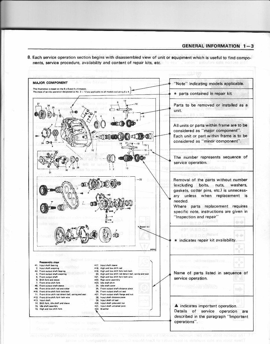
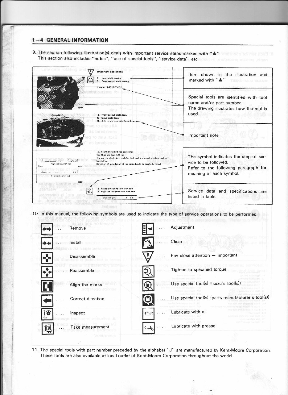
1-4 GENERAL INFORMATION V @ lmportant operrtions l lnFlrh6ftb€rring - 3. Front outpul ftrft b.rring lnstaller. 9.8522.0O4O.0 _r\ __r-t\_____r_.\ 8. F?ont dtpul !h.lt tlolvr 17. lnput rheft rloor. The shitt lork groove side taces downward. I rdr - oool H'9h 6.d low rh't ro. 1r@nr d ooj L Front dra !h,lt rcd L- "i-l 9. F.ontdrivcrhih rod.rd coll.r 18. High.rd low rhifl rod The pans rnclude thift rodr lor high and low tpeed relection and for Direction ot inilallarion of the pans thould b€ carefullv nored. To,que ltg ml 4 5 5 Fronl driv. ihilt lork lock bolt High lrd low shiti lork lock bll Item shown in the illustration and marked with "4" Special tools are identified with tool name and/or part number. The drawing illustrates how the tool is used. lmportant note. The symbol indicates the step of ser- vice to be followed. Refer to the following paragraph for meaning of each symbol. Service data and specif ications are listed in table. 9. The section following illustration(s) deals with important service steps marked with "A" This section also includes "notes". "use of special tools", "service data", etc. 10. ln this manual. the following symbols are used to indicate the type of service operations to be performed. tr E E E H E tr @ . Remove . lnstall . Disassemble Reassemble Align the marks Correct direction lnspect Take measurement Adjustment Clean Pay close attention - imPortant Tighten to specified torque Use special tool(s) (lsuzu's tool(s)) Use special tool(s) (parts manufacturer's tool(s)) Lubricate with oil Lubricate with grease ffi 6 V q @ @[ tr tr 11. The special tools with part number preceded by the alphabet "J" are manufactured by Kent-Moore Corporation. These tools are also available at local outlet of Kent-Moore Corporation throughout the world.
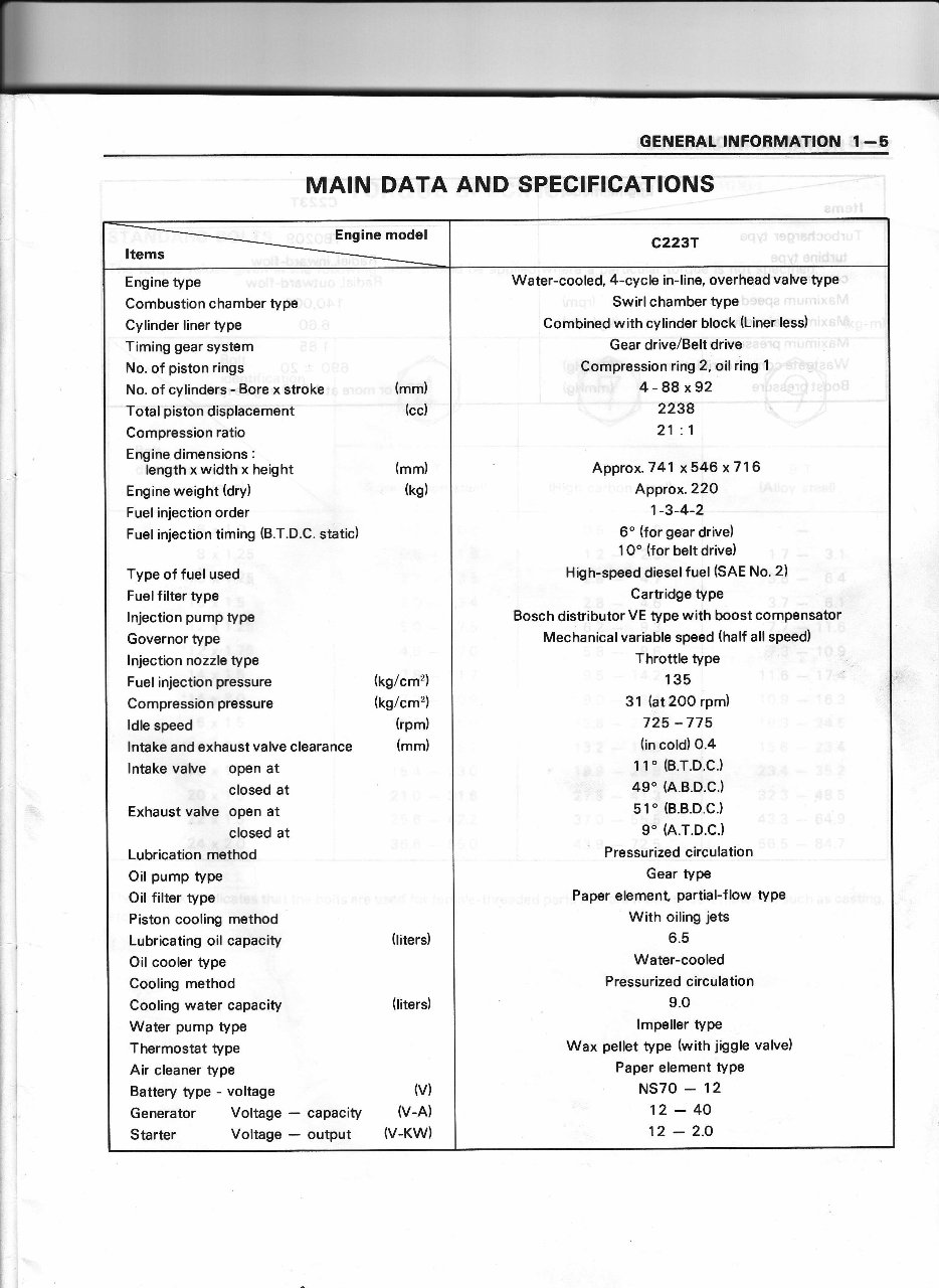
GENERAL INFORMATION 1 -5 MAIN DATA AND SPECIFICATIONS Engine model Items c2237 Engine type Combustion chamber type Cylinder liner type Timing gear system No. of piston rings No. of cylinders - Bore x stroke (mm) Total piston displacement (cc) Compression ratio Engine dimensions : lengthxwidthxheight Engine weight (dry) Fuel injection order Fuel injection timing (B.T.D.C. static) Type of fuel used Fuelfilter type lnjection pump type Governor type lnjection nozzle type Fuel injection pressure Compression pressure ldle speed lntake and exhaust valve clearance lntake valve open at closed at Exhaust valve open at closed at Lubrication method Oil pump type Oil filter type Piston cooling method Lubricating oil capacity Oil cooler type Cooling method Cooling water capacity Water pump type Thermostat type Air cleaner type Battery type - voltage Generator Voltage Starter Voltage (titers) (liters) capacity output v) v-A) V.KW) (mm) (kg) (tg/cm') (kg/cm'z) (rpm) (mm) Water-cooled, 4-cycle in-line, overhead valve type Swirl chamber type Combined with cylinder block (Liner less) Gear drive/Belt drive Compression ring2,oil ring 1 4-88x92 2238 21 :1 Approx. 741 x546 x7'l 6 A,pprox.22O 1-3-4-2 6o (for gear drive) 1O" (for belt drive) High-speed dieselfuel (SAE No. 2) Cartridge type Bosch distributor VE type with boost compensator Mechanicalvariable speed (half all speed) Throttle type 135 31 (at 2OO rpm) 725 -775 (in cold) 0.4 1 1" (B.T.D.C.) 49'(A.B.D.C.) 51' (B.B.D.C.) 9" h.T.D.C.) Pressurized circulation Gear tYPe Paper element partial-flow tYPe With oiling jets 6.5 Water-cooled Pressurized circulation 9.O lmpeller tyPe Wax pellet type (with jiggle valve) Paper element tYPe NS70 - 12 12-40 12 - 2.O
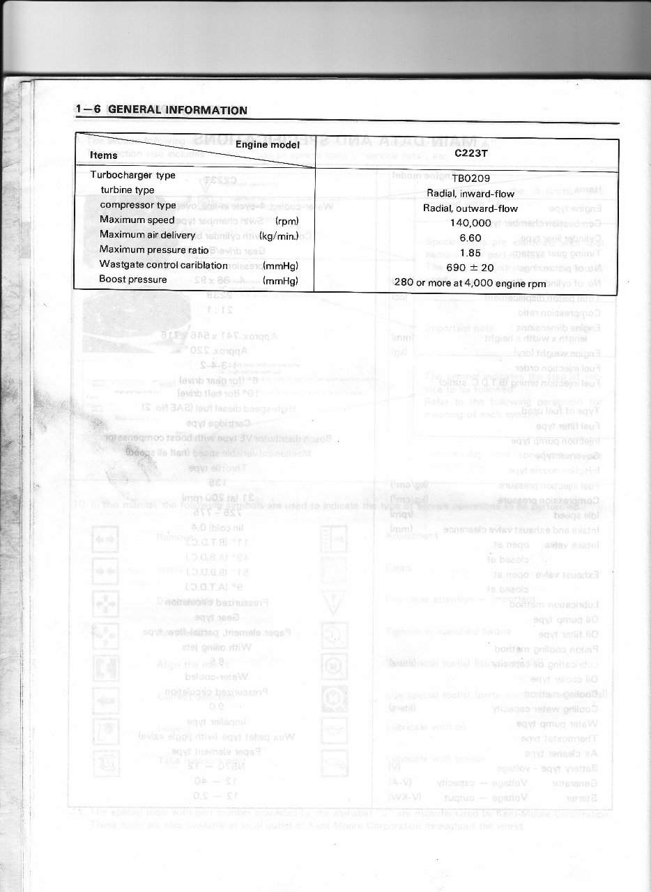
I€ ENEfiAT.' I NFO RMATION Engine model Items c2237 Turbocharger type turbine type compressor type Maximumspeed", (rpm) Maximumair delivery (kg/min.) Maximum pressure ratio Wastgate controlcariblation (mmHg) Boost pressure (mmHg) TBO209 Radial, inward-flow Radial, outward-flow 140.OOO 6.60 1.85 690 :t 20 28O or more at4,OO0 engine rpm
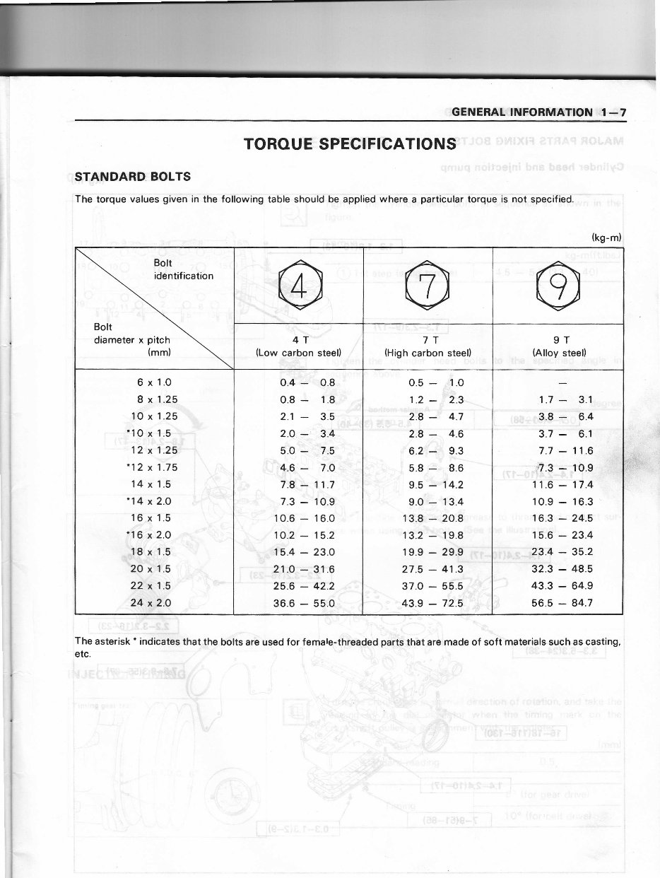
:,iGEff'EftAftel mqmffim@fl .€t-{7 TOROU E SPEGIFICATIO NS' STAilIDARD BOLTS :ihe tor{ue values given in the foliowing table shouid be bpplied where a particu-lar tbrque is n-oi ipecified. 1 ri I, i: -S.3 , The asterisk' indicates that the bolts arb used for female-thieadgd part6'thbt are made of soft materials such as casting, : etc. , r\.{. "",:,:ri il t'a_: -il (kg-m); Bolt identif ication Bolt diameter x pitch (mm) 4T " (Low carbon steel) l, 7T (High carbon steel) 9T (Alloy steel) 6 x 1.O 8 x 1.25 10 x 1.25 '1O x 1.5 - r't '12 x 1.fr '12 x 1.75 14 x 1.5 '14 x 2.O 16 x 1.5 116 x 2.0 \8'x 1.5 Q\,r" \O x--1.5 22\ 1.s : 24. io 0.4 - o.8 0.8 - 1.8. 2.1 - 3.5 2.O - 3.A $.Q - ./,9 , :.1,6 - 7.0 7.8 - 11.7 7.3 - 10.9 10.6 - 16.0 10.2 - 15.2 f5.4 - 23.0 ,!1-O_1;31;6 25.6 :42.2 36.6 - 55 0.5 - .:1.0 1.2 -'t'r.g- ':1,' :" l 2.8 - 4.7 2.8 - 4.6 6.2 - 9.3 5.8 ; 8.6 9.5'-. 1'4.2 9.0 ,- 13.4 13.8 - 20.8 13.2 : 19.8 19.9 - 29.9 ;i* ! t'l 27.5 - 41.5*- . 37.0-55.5j.J :i 43.9 - 72.5 'z 1.7 - 3.1 r.*. .r'3,.8 - 6.4 .J 3.7 - 6.1 7.7 - 11.6 ,fl.3 : Jo.e - -: !+tr-<'* t 11 .6 - 17.4 10.9 - 16.3 r 6.3 - 24.5 15.6 - 23.4 ,i" ""- J,3.4 - 35.2 E _j+-"F'.$,t 32.3 - 48.5 ' ,' 43.3 - 64.9 . 56.5 - 84.7 ;:il -# {t#
1 -8 GENERAL INFORMATION MAJOR PARTS FIXING BOLTS Cylinder head and injection pump (kg-m) ----4 Y ffi1-@ 1.3-1.8(1F13) 1.8-2.411T171 2.2-3.2116-231 -"'t: ?C __-tr.:--- ':'.O----H, 16-18(116-130)
The 1981-1993 Chevrolet LUV Service & Repair Manual is an essential resource for owners and enthusiasts of these classic Chevrolet vehicles. Whether you're a DIY mechanic or a professional technician, this comprehensive manual provides all the technical information and step-by-step instructions needed to properly maintain, repair, and service your Chevrolet LUV.
1981 Chevrolet LUV
1982 Chevrolet LUV
1983 Chevrolet LUV
1984 Chevrolet LUV
1985 Chevrolet LUV
1986 Chevrolet LUV
1987 Chevrolet LUV
1988 Chevrolet LUV
1989 Chevrolet LUV
1990 Chevrolet LUV
1991 Chevrolet LUV
1992 Chevrolet LUV
1993 Chevrolet LUV
From basic maintenance tasks like oil changes and tire rotation to more complex repairs and troubleshooting, the manual includes detailed diagrams, practical tips, and clear explanations on engine systems, transmission, suspension, brakes, electrical components, and more. It offers the accurate technical guidance required to keep your Chevrolet LUV in peak performance.
With this Service & Repair Manual, confidently tackle any repair or service task on your Chevrolet LUV 1981-1993, saving time and money compared to dealership visits or hiring a professional mechanic. Invest in this manual to ensure your beloved LUV remains in top-notch condition and continues to deliver reliable performance.