1996 Chevrolet Chevy Van (G30) Service & Repair Manual
What's Included?
Lifetime Access
Fast Download Speeds
Online & Offline Access
Access PDF Contents & Bookmarks
Full Search Facility
Print one or all pages of your manual
A/C COMPRESSOR CLUTCH CONTROLS 1996 A/C COMPRESSOR CLUTCH CONTROLS General Motors DESCRIPTION & OPERATION Turning on A/C system supplies battery voltage to the A/C compressor clutch and A/C request signal terminal of Engine Control Module (ECM), Powertrain Control Module (PCM) or Vehicle Control Module (VCM). When the ECM, PCM or VCM sees battery voltage at A/C request signal terminal, it maintains idle speed. The ECM, PCM or VCM does not control A/C compressor clutch operation. An A/C pressure cycling switch is used to control A/C compressor clutch operation. TROUBLE SHOOTING A/C CLUTCH CIRCUIT DIAGNOSIS - EXCEPT 6.5L Turning on A/C system supplies battery voltage to A/C compressor clutch and Powertrain Control Module (PCM) terminal E12 through Dark Green wire, increasing idle speed. PCM does not control A/C compressor clutch. If A/C compressor clutch is malfunctioning, repair basic A/C system problem. If A/C system is operating properly and idle speed drops too low when A/C compressor turns on or flares too high when A/C compressor turns off, check for an open circuit in Dark Green wire to PCM. If wiring is okay, repair faulty PCM connection (terminal E12) or replace faulty PCM. A/C CLUTCH CIRCUIT DIAGNOSIS - 6.5L Turning on A/C system supplies battery voltage to A/C compressor clutch and Powertrain Control Module (PCM) terminal PB4 through Dark Green wire, increasing idle speed. PCM does not control A/C compressor clutch. If A/C compressor clutch is malfunctioning, repair basic A/C system problem. If A/C system is operating properly and idle speed drops too low when A/C compressor turns on or flares too high when A/C compressor turns off, check for an open in Dark Green wire to PCM. If Dark Green wire is okay, repair faulty PCM connection (terminal PB4) or replace faulty PCM. NOTE: All models use Engine Control Module (ECM), Powertrain Control Module (PCM) or Vehicle Control Module (VCM) to maintain engine idle speed during A/C compressor clutch operation. These trucks do not use ECM, PCM or VCM to control A/C compressor clutch circuit. 1996 Chevrolet Chevy Van G30 A/C COMPRESSOR CLUTCH CONTROLS 1996 A/C COMPRESSOR CLUTCH CONTROLS General Motors
AIR BAG RESTRAINT SYSTEM 1995 ACCESSORIES/SAFETY EQUIPMENT General Motors Air Bag Restraint System IDENTIFICATION All models equipped with a Supplemental Inflatable Restraint (SIR) system have a number "2" (driver and passenger-side air bags) or "3" (driver-side air bag only) in the seventh position of the Vehicle Identification Number (VIN). Some vehicles have the words Supplemental Inflatable Restraint or SIR on the inflator module. Steering wheel hub is slightly larger in order to accommodate the driver-side air bag. DESCRIPTION & OPERATION SUPPLEMENTAL INFLATABLE RESTRAINT (SIR) SYSTEM The Supplemental Inflatable Restraint (SIR) system is designed to protect the driver and passenger (if equipped) in a frontal collision. The air bag(s) will deploy only upon frontal or near frontal impact of no more than 30 degrees off the center line of vehicle. System is not designed to deploy in rear impacts, side impacts, or rollovers. A frontal impact of sufficient severity (comparable to a collision into a solid wall at approximately 14 MPH or more) will cause sensors in vehicle to detect this sudden deceleration. These sensors, in turn, trigger the inflator module(s). DIAGNOSTIC ENERGY RESERVE MODULE (DERM) Vehicles not equipped with a Sensing and Diagnostic Module (SDM) are equipped with a DERM. DERM performs diagnostic monitoring of all system components, stores both current and past SIR system fault code information, warns driver of SIR system faults by controlling AIR BAG warning light, and records SIR system status during a vehicle accident. In addition, DERM maintains a 36-Volt Loop Reserve (36VLR) energy supply to provide sufficient deployment energy for about 2 minutes if vehicle system voltage is low or is lost in an accident. A 24-pin connector connects DERM to SIR harness. Harness connector uses gold-plated terminals and shorting bar in terminal contact area. DERM connector also has a gold-plated shorting bar that connects AIR BAG warning input to ground when the DERM connector is disconnected. With DERM disconnected, AIR BAG warning light remains on when ignition switch is in RUN, BULB TEST, or START positions. DERM is located under or behind instrument panel. AIR BAG RESTRAINT WARNING LIGHT When ignition switch is in RUN, BULB TEST, or START positions, battery voltage is applied to AIR BAG warning light. DERM/SDM illuminates this light by providing a ground to a lamp driver. Some vehicles are NOTE: Following SIR components are not necessarily installed on all vehicles. NOTE: Some vehicles have an INFLATABLE RESTRAINT warning light as opposed to an AIR BAG warning light. 1996 Chevrolet Chevy Van G30 AIR BAG RESTRAINT SYSTEM 1995 ACCESSORIES/SAFETY EQUIPMENT General Motors Air Bag Restraint System
equipped with a Serial Data Controlled Warning Lamp (SDCWL). An SDCWL equipped vehicle utilizes a smart cluster which communicates via the serial data line, so in this case, DERM/SDM transmits a request to turn on AIR BAG warning light. When ignition is first turned on, AIR BAG warning light verifies light and DERM/SDM operation by flashing 7-9 times. Light is also used to warn driver of SIR electrical system faults which could potentially affect SIR system operation. AIR BAG warning light is the key to driver notification of SIR system faults. In addition, the light provides diagnostic information by flashing Diagnostic Trouble Codes (DTCs) when the flash code diagnostic mode is entered on models without on-board diagnosis. INFLATABLE RESTRAINT indicator light notifies driver of SIR system faults. ARMING SENSOR/DUAL POLE ARMING SENSOR Arming sensor/dual pole arming sensor is a protective switch located in power feed side (positive side) of deployment loop. It is calibrated to close at low-level velocity changes (lower than discriminating sensors). This assures that each inflator module is connected directly to 36VLR output of DERM or ignition voltage when either of the discriminating sensors close. Arming sensor/dual pole arming sensor consists of a sensing element, normally open switch contacts, a diagnostic resistor, and 2 diodes. Sensing element closes switch contacts when velocity of vehicle changes at a rate indicating potential need for deployment. A diagnostic resistor is connected in parallel with normally open switch contacts and allows for a small amount of current flow through deployment loop during normal undeployed conditions. This small current flow results in voltage drops across each component within loop. DERM monitors these voltage drops to detect circuit or component faults. The 2 diodes provide isolation between 36VLR output of DERM and ignition voltage. In some vehicles, arming sensor is combined with passenger compartment discriminating sensor. DISCRIMINATING SENSORS Most SIR systems have 2 discriminating sensors. Some vehicles have 2 forward discriminating sensors, while other vehicles have one forward discriminating sensor and a passenger compartment discriminating sensor, or 2 mid-rail discriminating sensors. Forward discriminating sensor is located on radiator support brace or tie bar. Passenger compartment discriminating sensor is located under center of instrument panel/console area or under front passenger seat. Mid-rail discriminating sensors are located on side mid-rails in engine compartment. In some vehicles, the passenger compartment discriminating sensor is combined with arming sensor. Discriminating sensors are wired in parallel on the ground side of deployment loop. These sensors are calibrated to close when deceleration velocity changes are severe enough to warrant deployment. Sensors consist of a sensing element, normally open switch contacts, and a diagnostic resistor. Sensing element closes the normally open switch contacts when vehicle velocity changes are severe enough to warrant deployment. A diagnostic resistor is connected in parallel with the normally open switch contacts within each of the sensors. These parallel resistors supply the ground path for current passing through the deployment loop during normal undeployed conditions. This small current flow results in a voltage drop across each component within loop. DERM monitors these voltage drops to detect circuit or component faults. 1996 Chevrolet Chevy Van G30 AIR BAG RESTRAINT SYSTEM 1995 ACCESSORIES/SAFETY EQUIPMENT General Motors Air Bag Restraint System
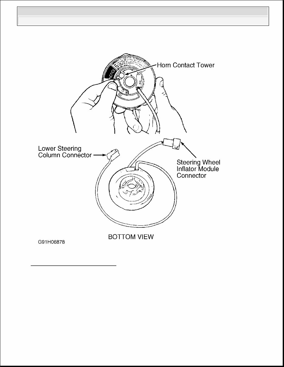
SIR COIL ASSEMBLY SIR coil assembly consists of 2 current-carrying coils. It is installed in steering column and allows rotation of steering wheel while maintaining continuous (directly wired) contact of deployment loop through steering wheel inflator module. Slip rings are not used in SIR system to transmit current from column to steering wheel. Gold-plated terminals and a shorting bar are used on coil assembly lower steering column Yellow connector. Shorting bar shorts the circuits to main coil and steering wheel inflator module when lower steering column connector is disconnected. This shorts the circuit to the inflator module(s), preventing unwanted deployment of the air bag(s) when servicing the steering column or other SIR components. INFLATOR MODULE When the vehicle is in an accident of sufficient force to simultaneously close the arming sensor and at least one discriminating sensor, nitrogen gas inflates the cloth bag packed inside the steering wheel hub and in passenger- side instrument panel, (if equipped). The bag(s) inflate in less than 1/20 of a second. As air bag is contacted by driver or passenger, the gas is vented through openings in the bag, which deflates almost as soon as it is completely deployed. RESISTOR MODULE Resistor module is located in SIR harness between inflator module and DERM. Resistor module allows DERM to monitor deployment loop for faults and to detect when a deployment has occurred. Resistors in resistor module are balanced with resistors on arming and discriminating sensors to allow DERM to monitor voltage drops across the components of the deployment loop. Faults are detected during normal undeployed conditions by monitoring these voltages. On some vehicles, resistor module is mounted on DERM. SYSTEM OPERATION CHECK If system is functioning normally, air bag warning light flashes 7-9 times when ignition switch is turned to ON position and goes out. Four possible warning light conditions can indicate a system failure: Light does not illuminate at all. Light comes on while vehicle is driven. Light flashes 7-9 times, and remains on. Light does not flash but remains lit when ignition is turned on. SIR system faults are usually due to a disconnected/loose electrical connector caused by previous service on vehicle. Always check Yellow SIR connector at base of steering column for loose or damaged wiring. POST-COLLISION INSPECTION When a vehicle has been involved in a collision, certain components of the passive restraint system must be 1996 Chevrolet Chevy Van G30 AIR BAG RESTRAINT SYSTEM 1995 ACCESSORIES/SAFETY EQUIPMENT General Motors Air Bag Restraint System
inspected or replaced. See PASSIVE RESTRAINT SYSTEM INSPECTION article in the GENERAL INFORMATION section for post-collision inspection information. INTERMITTENTS & POOR CONNECTIONS Most intermittents are caused by faulty electrical connections or wiring, or a sticking relay or solenoid. Items to check are: Poor mating or connector halves, or terminals not fully seated in connector Dirt or corrosion on terminals. Terminals must be clean and free of any foreign material which could impede proper terminal contact. Damaged connector, exposing the terminals to dirt and moisture, as well as not maintaining proper terminal orientation with the component or mating connector. Improperly formed or damaged terminals. All connector terminals in problem circuit(s) should be checked carefully to ensure good contact. Connector Test Adapter Kit (J-35616-A) must be used whenever a diagnostic procedure requests checking or probing a terminal. Using adapter will ensure that no damage to terminals will occur, as well as giving an idea whether contact is sufficient. Poor terminal-to-wire connections. some conditions which fall under this description are poor crimps, poor solder joints, crimping over wire insulation rather than the wire itself, or corrosion in the wire-to- terminal contact area. Wire Insulation which is rubbed through, causing an intermittent short as the bare area touches other wiring or parts of vehicle. Broken wires inside insulation. Perform continuity check while flexing wiring harness to find location of broken wires. SERVICE PRECAUTIONS SYSTEM REPAIR Before any repairs are performed, disconnect and shield battery ground. Because system has ability to retain voltage, remove SIR or AIRBAG fuse, and disconnect Yellow SIR connector at base of steering column, and, on vehicles with passenger-side air bags, disconnect Yellow SIR connector at base of right instrument panel (behind knee bolster). Wait 2 minutes before working on vehicle. All connectors used on SIR system use Connector Position Assurance (CPA) clips to ensure connector retention. Even if system is disconnected, always use caution when working near inflator modules. SENSOR HANDLING CAUTION: Correct operation of sensors and SIR system requires any repairs to vehicle structure return it to its original production configuration. Deployment requires, at a minimum, replacement of inflator module(s) and sensors in area of accident damage. 1996 Chevrolet Chevy Van G30 AIR BAG RESTRAINT SYSTEM 1995 ACCESSORIES/SAFETY EQUIPMENT General Motors Air Bag Restraint System
Use special care when handling a sensor. DO NOT strike or jar a sensor, as air bag deployment, personal injury or improper operation of SIR system could result. A sensor must be replaced if dropped 3 feet or more. Sensors and mounting bracket bolts must be carefully torqued to ensure correct operation. Never power up SIR system when any sensor is not rigidly attached to vehicle, since sensor is easily activated and could cause air bag deployment. LIVE INFLATOR MODULE HANDLING When carrying a live inflator module, ensure bag and trim cover are pointed away from body. If an accidental deployment occurs, bag will then deploy with reduced chance of injury. When placing a live inflator module on a bench or other surface, always face bag and trim cover up and away from surface so space is provided to allow air bag to expand in case of deployment. In addition, never carry any SIR component by wires or connector. SPECIAL TOOLS To avoid deployment when working on SIR system, DO NOT use electrical test equipment such as test lights, battery or A/C-powered volt/ohmmeter, or any type of electrical equipment other than those specified by manufacturer. See SIR RECOMMENDED TOOLS table. SIR RECOMMENDED TOOLS DISABLING & ACTIVATING AIR BAG SYSTEM DISABLING SYSTEM 1. Turn steering wheel to place vehicle wheels in straight-ahead position. Turn ignition switch to LOCK position. WARNING: Special care is necessary when handling and storing a live (undeployed) inflator module. Rapid gas generation, produced during deployment of air bag, could throw inflator module, or any object in front of inflator module, through air, possibly causing serious injury. Tool Name Tool Number Connector Test Adapter Kit J-35616-A Digital Volt/Ohmmeter J-39200 Inflator Module & Steering Column Replacement Load J-37808 Or J-38715 Wire Repair Kit J-38125-A CAUTION: When battery is disconnected, vehicle computer and memory systems may lose memory data. Driveability problems may exist until computer systems have completed a relearn cycle. Record customer radio stations, as memory will be lost. Code equipped radios may also lock. Obtain code from customer. See COMPUTER RELEARN PROCEDURES in GENERAL INFORMATION before disconnecting battery. 1996 Chevrolet Chevy Van G30 AIR BAG RESTRAINT SYSTEM 1995 ACCESSORIES/SAFETY EQUIPMENT General Motors Air Bag Restraint System
2. Remove SIR or AIRBAG fuse. Remove CPA clip and disconnect Yellow SIR connector at base of steering column (it may be necessary to remove left sound insulator). If equipped with passenger-side air bag, disconnect Yellow SIR connector under right instrument panel or behind glove box door assembly. Some models have access to connector through a trap door in glove box. 3. Wait 2 minutes before beginning service. All connectors in SIR system use CPA clips to ensure connector retention. Even if system is disconnected, use caution when working near air bags. ACTIVATING SYSTEM Connect Yellow SIR connector at base of steering column, and under right side instrument panel, if equipped. Install CPA clips and fuse. Turn ignition switch to RUN position and ensure AIR BAG warning light flashes 7- 9 times and then goes out. ADJUSTMENTS CENTERING COIL ASSEMBLY 1. If coil assembly has been removed from steering column and is being reinstalled, go to next step. New coil assemblies are provided pre-centered and include a Blue plastic tab that is snapped off once coil is installed. See Fig. 1 . 1996 Chevrolet Chevy Van G30 AIR BAG RESTRAINT SYSTEM 1995 ACCESSORIES/SAFETY EQUIPMENT General Motors Air Bag Restraint System
Fig. 1: Installing SIR Coil Assembly Courtesy of GENERAL MOTORS CORP. 2. Ensure front wheels face straight ahead when installing or removing a coil assembly. If coil is removed without wheels in straight-ahead position and steering wheel has not been moved, same coil can be reinstalled if coil hub has not been rotated. 3. Hold coil assembly with clear bottom upward to see coil ribbon. Note there are 2 different styles of coil assemblies: one rotates clockwise and other counterclockwise. 4. While holding coil assembly housing, depress spring lock and rotate hub in direction of arrow until it stops. Coil assembly should now be wound up snug against center hub. Rotate coil assembly hub in opposite direction approximately 2 1/2 turns. Release spring lock between locking tabs in front of arrow. 1996 Chevrolet Chevy Van G30 AIR BAG RESTRAINT SYSTEM 1995 ACCESSORIES/SAFETY EQUIPMENT General Motors Air Bag Restraint System
DISPOSAL PROCEDURES DEPLOYED AIR BAG Once an inflator module has been deployed, surface of air bag may contain a small amount of sodium hydroxide dust, combined with a White packing powder. Sodium hydroxide dust can be irritating to skin if left on for an extended period of time. Always wear gloves and safety glasses when handling a deployed inflator module. Wash hands with mild soap and water afterward. Deployed air bag modules can be disposed of as would any other part. Handle air bag module with gloves, and wear safety glasses. UNDEPLOYED AIR BAG Undeployed air bag modules must not be disposed of at normal refuse locations. Undeployed air bag modules contain substances which can cause illness or injury if handled improperly. Disposal of air bag module in any manner inconsistent with proper procedures may be a violation of federal, state and/or local laws. If possible, deploy air bag module in vehicle. See SCRAPPED VEHICLE. Transportation of undeployed inflator modules is regulated by hazardous materials regulations of U.S. Government Department of Transportation and most state governments. Special shipping procedures must be followed. Check with hazardous material section of state government for applicable shipping requirements. SCRAPPED VEHICLE Some vehicles which have to be scrapped may have undeployed SIR systems. When scrapping a vehicle with an undeployed module: 1. Turn ignition switch to OFF position. Remove SIR fuse. Disconnect Yellow 2-pin connector at base of steering column. Cut harness side of SIR wiring approximately 3-6" from Yellow 2-pin connector. 2. Splice 2 wires at least 20 feet long to wiring cut from SIR harness. Connect Yellow 2-pin connector. 3. Ensure inflator module is secured to steering wheel. Remove all loose objects from front seat, and ensure no one is in vehicle. Stretch wires away from car as far as possible. 4. Connect wires to a 12-volt battery. Air bag should deploy. DO NOT touch inflator module area for 20 minutes due to heat generated during deployment. Wear gloves and safety glasses before handling deployed air bag. Wash hands with mild soap and water afterward. 5. On vehicles with passenger-side air bags, repeat deployment procedure for passenger-side. Access Yellow 2-pin connector at base of right instrument panel (behind knee bolster) or behind glove box door assembly. CAUTION: If SIR inflator is disposed of improperly, air bag deployment may result and cause personal injury. Undeployed inflator modules must not be disposed of at normal refuse locations. Undeployed inflator modules contain substances which can cause severe illness or personal injury if sealed container is damaged during disposal. Disposal of module in any manner inconsistent with proper procedures may be a violation of federal, state, and/or local laws. 1996 Chevrolet Chevy Van G30 AIR BAG RESTRAINT SYSTEM 1995 ACCESSORIES/SAFETY EQUIPMENT General Motors Air Bag Restraint System
REMOVAL & INSTALLATION DERM Removal 1. Before proceeding, follow service precautions. See SERVICE PRECAUTIONS. Disable air bag system. See DISABLING & ACTIVATING AIR BAG SYSTEM. 2. DERM is located on bracket next to parking brake assembly. Remove CPA clip and disconnect electrical connector from DERM. Remove DERM from mounting bracket. Installation To install, reverse removal procedure. Reactivate air bag system. See DISABLING & ACTIVATING AIR BAG SYSTEM. Check AIR BAG warning light to ensure system is functioning properly. See SYSTEM OPERATION CHECK. ARMING SENSOR/DUAL POLE ARMING SENSOR Removal & Installation 1. Before proceeding, follow air bag service precautions. See SERVICE PRECAUTIONS. Disable air bag system. See DISABLING & ACTIVATING AIR BAG SYSTEM. 2. Arming sensor is located under vehicle, at front crossmember. Raise and support vehicle. Disconnect electrical connectors. Remove sensor from vehicle. See Fig. 2 . To install, reverse removal procedure. Tighten retaining bolts to 71 INCH Lbs. (8 N.m). WARNING: Failure to follow air bag service precautions may result in air bag deployment and personal injury. See SERVICE PRECAUTIONS. After component replacement, perform a system operational check to ensure proper system operation. See SYSTEM OPERATION CHECK. 1996 Chevrolet Chevy Van G30 AIR BAG RESTRAINT SYSTEM 1995 ACCESSORIES/SAFETY EQUIPMENT General Motors Air Bag Restraint System
If you are in need of a repair manual for your 1996 Chevrolet G30 VAN, look no further. Our accessible repair manual provides comprehensive coverage for the Chevrolet G30 VAN, making it ideal for both professional mechanics and DIY enthusiasts.
Gone are the days of purchasing traditional service manuals in book format at a higher cost. Our repair manual offers the same valuable information in a more affordable and convenient digital format.
Whether you require guidance for brake repairs, suspension component replacements, engine troubleshooting, or standard maintenance procedures, this repair manual for the Chevrolet G30 VAN has you covered.
With this , you will have access to a wealth of service information, including but not limited to brakes, engine, suspension, steering, drivetrain, electrical systems, heating, and air conditioning. It equips you with the knowledge to address any automotive issue.
By utilizing this 1996 Chevrolet G30 VAN repair manual , you can save a significant amount of money on vehicle maintenance. Take advantage of the cost-effectiveness of DIY repairs, bypassing the high labor fees typically charged by mechanics.
Our is designed for ease of use and is compatible with Windows, Mac computers, smartphones, and tablets, ensuring accessibility across various devices.
Recently Viewed
5,521,897Happy Clients
2,594,462eManuals
1,120,453Trusted Sellers
15Years in Business
Price:
Actual Price:
1996 Chevrolet Chevy Van (G30) Service & Repair Manual